 Baiyu Li
 Jia Qiao2
 Zukun Lu
94% of researchers rate our articles as excellent or good
Learn more about the work of our research integrity team to safeguard the quality of each article we publish.
Find out more
ORIGINAL RESEARCH article
Front. Phys. , 09 January 2023
Sec. Space Physics
Volume 10 - 2022 | https://doi.org/10.3389/fphy.2022.1063474
The global navigation satellite system (GNSS), represented by global positioning systems (GPS), is widely used in various civil and military fields and represents an essential basis for space-time information services. However, the radar signals partially overlap with the frequency band of satellite navigation signals, seriously affecting the normal reception of weak satellite navigation signal power. To further improve anti-jamming with sweep interference in the time domain, this paper focuses on the sweep interference scenario, studies the influence of the sweep interference on time-domain-adaptive anti-jamming, and proposes a timing reset based on the adaptive filter. The proposed method can effectively deal with the influence of sweep interference on time-domain-adaptive anti-jamming and can suppress interference and protect signals at the same time. Simulation experiments verify the effectiveness of the anti-jamming method proposed in this paper. Under the typical simulation scenarios, the influence time of the frequency sweep interference on the navigation signal is less than 1 m when the timing reset period is 1 m, which is significantly reduced compared to traditional methods. The proposed anti-jamming method is of great significance for improving the survivability of satellite navigation receivers in sweep interference scenarios.
The Global Navigation Satellite System (GNSS) is satellite-based all-weather navigation, positioning, and timing system [1–3]. At present, the leading satellite navigation systems used around the world are the US GPS (Global Positioning System), the Chinese Beidou-3 global satellite navigation system, the Russian GLONASS (Global Navigation Satellite System), and the European Galileo system [4–7]. With the deterioration of the electromagnetic environment and the escalation of interference complexity, including concepts such as electronic warfare and navigation warfare, which have received a great deal of attention in modern combat systems, anti-jamming has become an essential function of satellite navigation receivers [8–11].
The anti-jamming technologies comprise the time/frequency domain anti-jamming technology, based on a single antenna, and space-domain anti-jamming technology, based on the antenna array [12, 13]. Space-domain anti-jamming technology can also be combined with other domain algorithms to form space-time and space-frequency technology. Antenna array anti-jamming technology uses multiple antenna array elements and vector weighting to cancel interference according to the difference in the signal direction angle and the interference direction angle [14, 15]. The single antenna has irreplaceable advantages in some application backgrounds compared to array anti-jamming technology, mainly reflected by the small size and convenience of the single antenna. The antenna can be customized according to the shape of the installation platform [16–19].
Time-domain anti-jamming technology based on linear estimation represents basic adaptive filtering theory [20]. It occupies fewer resources in developing and implementing the Field-Programmable Gate Array (FPGA) and other hardware and can be easily modularized. It can effectively suppress traditional narrowband interference, such as narrowband interference and sweeping-frequency interference. However, satellite navigation signals are usually in the L-band. Ground air traffic radars, active earth exploration satellites, satellite-to-ground mobile communication satellites, and aviation radio navigation, among others, are also in this frequency band [13, 21–23]. If the same frequency is used between different systems, there will be mutual interference between the different systems. For example, the air traffic control radar uses chirp signals, which overlap with the frequency point of the satellite navigation signal. Due to the weakness of the satellite navigation signal, air traffic control radar has a severe impact on the navigation signal. Due to the particularity of the air traffic radar signal, it has not received much attention from scholars. In an experiment in 2021, the author team found that sweeping-frequency interference not only deteriorates the performance of the air traffic control radar’s satellite navigation receiver but also seriously impacts time-domain adaptive anti-jamming performance.
Sweeping-frequency interference is a type of narrowband interference that takes place quickly. Traditional methods believe that time-domain-adaptive anti-jamming can effectively solve frequency sweep interference. However, according to our measurements in 2021, this is not the case, and we have reproduced the experimental scene. The sweeping-frequency interference will lead to the degradation of the time domain-adaptive anti-jamming performance. This paper mainly analyzes the mechanism of this phenomenon and proposes solving the time-domain-adaptive anti-jamming problem in the sweeping-frequency interference scenario.
The structure of this paper is as follows: Section 2 introduces the mathematical models studied in this paper, including the mathematical models of time-domain anti-jamming and sweeping-frequency interference. Section 3 analyzes the influence of sweeping-frequency interference on time-domain anti-jamming and provides theoretical analysis and simulation verification. Section 4 proposes a time-domain anti-jamming method under the condition of sweeping-frequency interference and verifies the proposed method via simulation. Section 5 builds an experimental verification platform and uses experimental instruments to verify the results analyzed in this paper and the proposed method. Finally, the conclusions of this paper are presented.
In the satellite navigation receiver, the antenna receives the navigation signal transmitted from the satellite and preprocesses the navigation signal through the radio frequency channel. These preprocesses include low-noise amplification, frequency mixing, filtering, intermediate frequency amplification, and other links, which can be collectively referred to as analog signal processing. Then, the analog signal is converted into a digital signal through an analog-to-digital converter (ADC). Digital signal processing is usually carried out in the FPGA and Digital Signal Processor (DSP). Signal flow is carried out in the FPGA, and the DSP is responsible for signal control and scheduling. The receiver functions include digital down-conversion (DDC), anti-jamming, acquisition, tracking, and other types of processing, and, finally, output PNT information. Anti-jamming processing is part of digital signal processing. The framework of the satellite navigation receiver is shown in Figure 1.
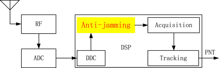
FIGURE 1. Satellite navigation receiver architecture.
The structure of the single antenna-based time-domain-adaptive anti-jamming filter is shown in Figure 2 [24, 25]. where

FIGURE 2. The time-domain anti-jamming filter structure.
The conventional adaptive algorithms for time-domain anti-jamming include the Least Mean Square (LMS) algorithm, which is based on the Minimum Mean Square Error (MMSE) criterion, and the Least Squares (LS) algorithm, which is based on the Recursive Least Squares (RLS) algorithm [26–28]. Among them, the LMS algorithm proposed by Widrow and Hoff in 1957 has the advantages of simple principles and no need for complex matrix inversion, and this method is widely used [29]. This paper only analyzes the LMS algorithm.
The output of the filter is set as
where
The desired signal of the filter is set as
The iterative formula for the weight coefficient of the LMS algorithm is as follows:
where
where
The filter structure used in this paper is a commonly used odd-order bilateral tap transversal filter; that is, it is a filter with an interpolation structure. Constraining the middle tap coefficient always to be one ensures that the weight vector does not converge to all zeros. The filter architecture is shown in Figure 3 [30–33]. Where
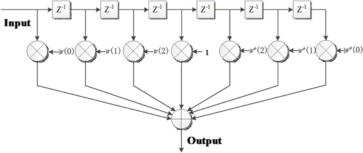
FIGURE 3. The architecture of the time-domain anti-jamming filter.
Sweeping-frequency interference is a commonly used modulation method in the radar field, and its complex signal expression is as follows [34]:
where
Assume that the sampling rate is 16.25 MHz, the frequency change range is linear from 0.05 MHz to 0.1 MHz, and the frequency change rate is 0.16 GHz/s. One cycle of the sweeping-frequency interference time-domain waveform is shown in Figure 4, and it can be seen that the frequency changes linearly [35].
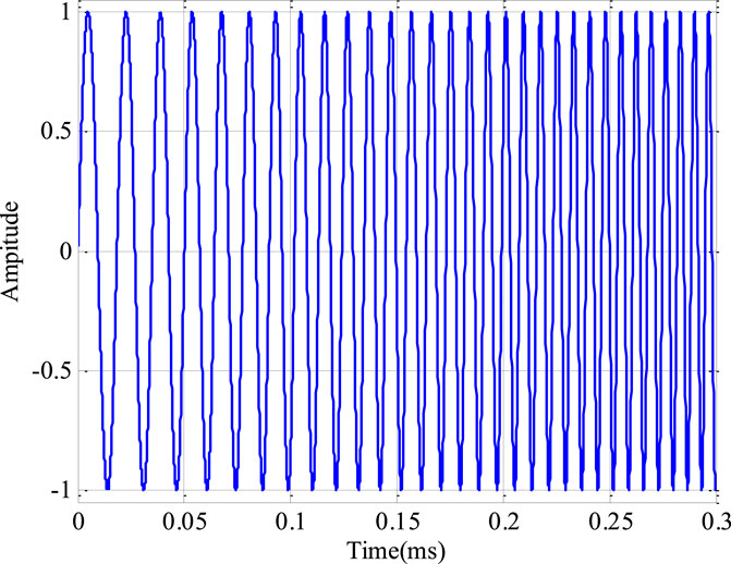
FIGURE 4. The time-domain waveform of sweeping-frequency interference.
Assume that the sampling rate is 16.25 MHz, the frequency change interval is 1 MHz, and the frequency change rate is 1 MHz/ms. Linear frequency modulation includes two frequency modulation methods: continuous frequency modulation (CFM) and discontinuous frequency modulation (DFM) [36, 37]. For CFM, the frequency increases linearly from 3 Mhz to 4 MHz in the first millisecond and from 12 Mhz to 13 MHz in the 10th millisecond. In the case of DFM, the frequency remains 3 MHz in the first millisecond and becomes 4 MHz at the beginning of the second millisecond; in the 10th millisecond, the frequency remains 12 MHz and becomes 13 MHz at the beginning of the 11th millisecond (The beginning of the 11th millisecond not shown in the Figure 7B).
The frequency variation expressions of the CFM and DFM are as follows:
where
where
The spectral characteristics of CFM and DFM are shown in Figures 5, 6, respectively. Each type of swept interference shows the spectrogram at 10 different times, and each interval is 1 m. The spectral characteristics can be shown via Power Spectral Density (PSD).
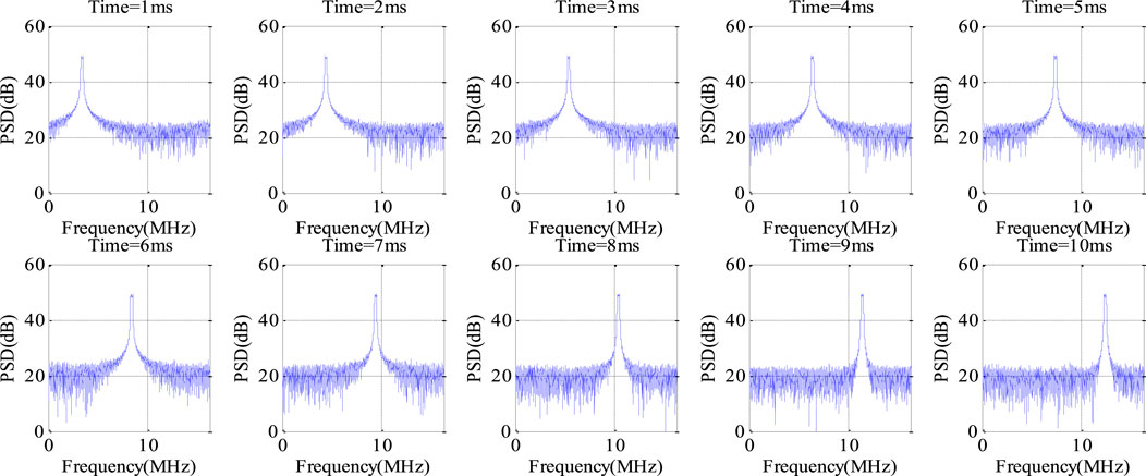
FIGURE 5. Frequency domain characteristics of CFM interference.
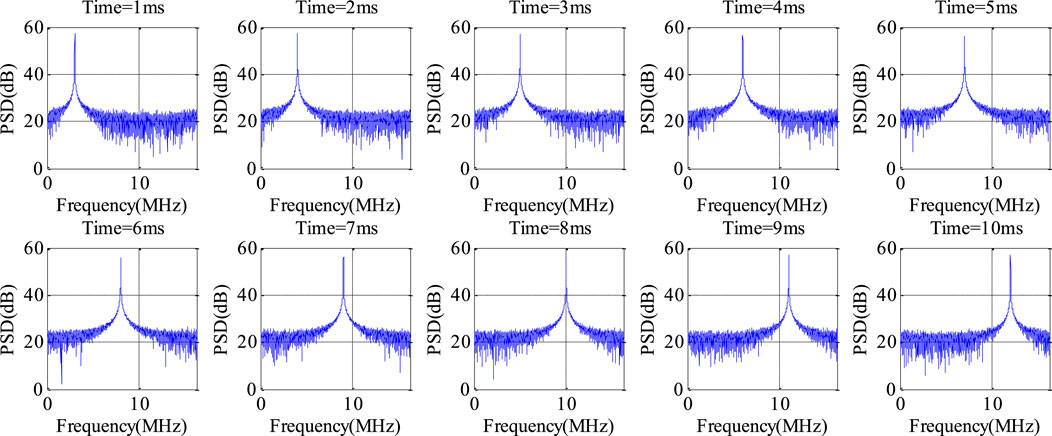
FIGURE 6. Frequency domain characteristics of DFM interference.
To express the frequency domain characteristics in the different periods more clearly, Figure 7 shows the time-frequency diagram of the generated sweeping-frequency interference data [38, 39]. Among them, the x-axis represents frequency, the y-axis represents time, and different colors represent different signal amplitudes. Red represents the most robust signal amplitude, and blue represents the weakest signal amplitude. It can be seen that the frequency change is consistent with the simulation settings. Figures 7A, B represent chirp signals, where the frequency of the signal changes linearly over time. Figure 7A shows the CFM, whose frequency changes are continuous, and Figure 7B shows the DFM, whose frequency changes are discontinuous, showing a step-by-step growth trend consistent with the expected effect.
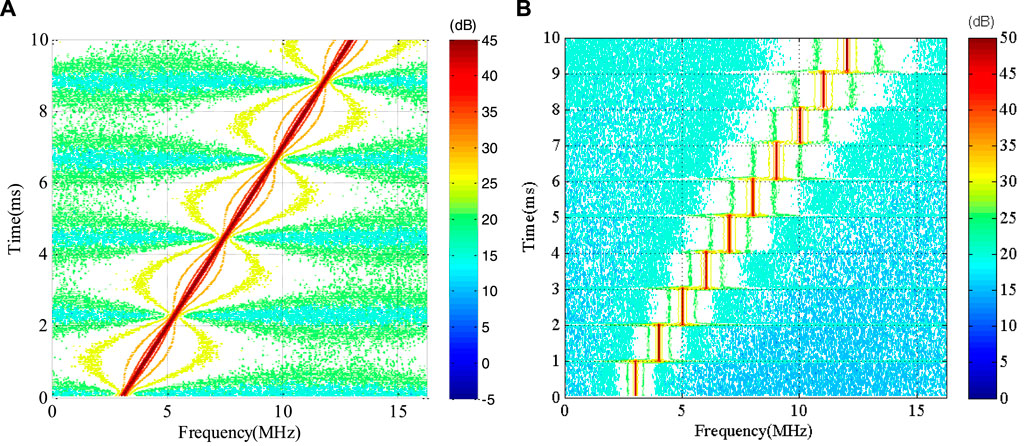
FIGURE 7. Time-frequency domain characteristics of sweeping-frequency interference. (A) CFM (B) DFM.
In scenarios applying a satellite navigation receiver, the signal power is about 30 dB lower than the noise power, and the interference power is more than 10 dB stronger than the noise power. Therefore, the reference signal of the time-domain-adaptive filter is usually set to 0, which is set to the minimum power guideline. On the one hand, the noise will not be suppressed under the constraint of the weight vector. On the other hand, the interference signal belongs to the narrow band in the bandwidth and can be suppressed by the adaptive filter.
Suppose that the swept interference hops from frequency
Figures 5, 6 show sweeping-frequency interference scenarios using the traditional time-domain-adaptive anti-jamming method. Figures 8, 9 show the spectrum after anti-jamming in each period. Time-domain-adaptive anti-jamming can form nulling at the interference frequency. As the interference frequency changes, the nulls at the original interference frequencies are still retained. The more the interference frequency changes, the more nulls are formed and the greater the equivalent effect on the navigation signal.
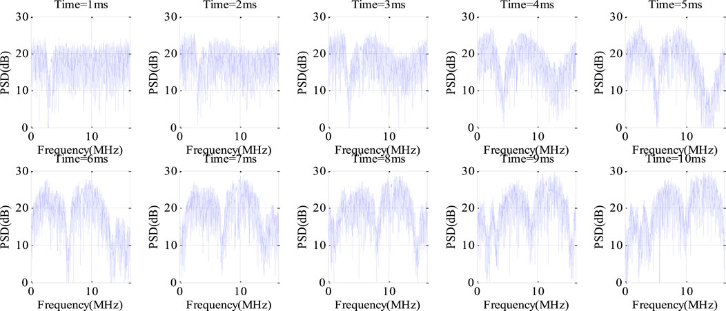
FIGURE 8. Spectral characteristics after anti-jamming (CFM).
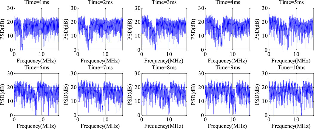
FIGURE 9. Spectral characteristics after anti-jamming (DFM).
The time-frequency analysis was performed on the data after anti-jamming to more clearly analyze the time-domain-adaptive anti-jamming process caused by sweeping-frequency interference. The time-frequency analysis results are shown in Figure 10. The time-frequency analysis of the sweeping-frequency interferenceshows that although the interference frequency has changed, there is still a null at the original interference frequency. When the interference frequency scans the entire signal bandwidth, several nulls appear in the signal spectrum, disturbing the signal spectrum structure and affecting the navigation signal demodulation.
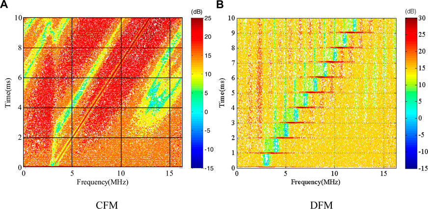
FIGURE 10. Time-frequency domain characteristics after anti-jamming. (A) CFM (B) DFM.
Under the conditions of the above simulation test scenarios representing continuous frequency modulation and discontinuous frequency modulation, taking the first weight coefficient of the weight vector as the analysis object, the modulus value of the weight coefficient in the continuous and discontinuous frequency modulation scenarios is shown in Figure 11 [40–42]. For the continuous frequency modulation interference, the change in the weight coefficient is relatively gentle, and there is no jumping point.
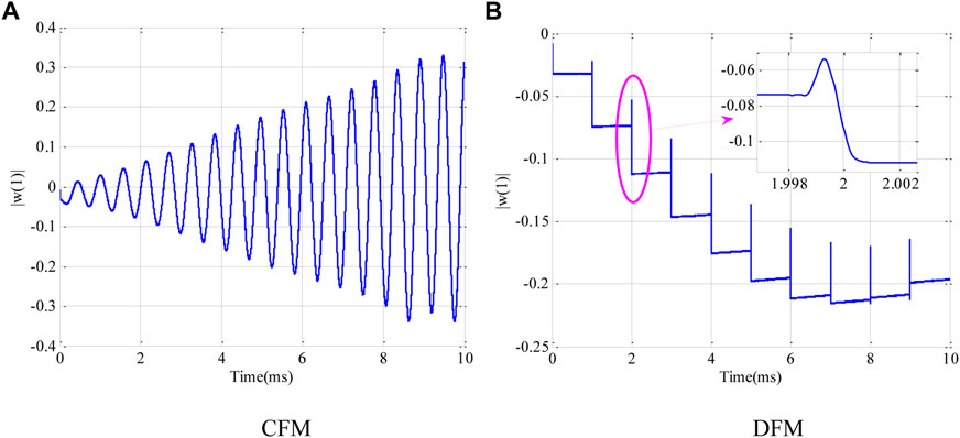
FIGURE 11. Adaptive convergence characteristics of sweeping-frequency interference suppression. (A) CFM (B) DFM.
However, for discontinuous frequency modulation, due to the frequency hopping of the interference, the weight coefficient generated by the adaptive filter also hops along with it. The weight coefficient experiences a relatively large jump when the interference frequency changes. In addition, even if the weight coefficients jump, the adaptive filter will quickly make the weight coefficients converge [43, 44]. In the context of this experiment, the convergence time is about 2us. For the reception of satellite navigation signals, data anomalies of this order of magnitude can be ignored.
Through the above analysis, the convergence time of the adaptive filter is negligible compared to the reception of the satellite navigation signals, and the abnormal anti-jamming processing shown in Figures 8–10 is caused by past interference; then, the filter can be reset according to the time to solve the problem caused by the sweeping-frequency interference to the adaptive anti-jamming filter. Figure 12 demonstrates the time-domain anti-jamming algorithm flow chart based on timing reset.
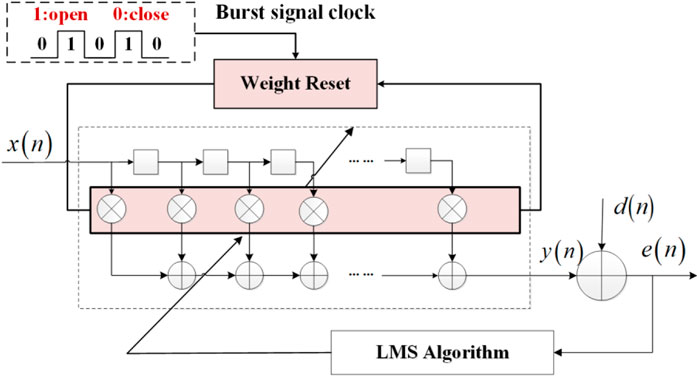
FIGURE 12. Algorithm flow chart based on timing reset.
Set the timing reset period to 1 m. According to the above simulation scenario, the weight coefficient value under continuous frequency modulation and discontinuous frequency modulation is shown in Figure 13. The results demonstrate that the improved time cost is meager, the convergence time is less than 1us, and the impact on the quality of the navigation signal is negligible.
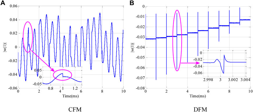
FIGURE 13. Impact of timing reset on adaptive convergence. (A) CFM (B) DFM.
Under the experimental conditions shown in Figures 8, 9, a timing reset method for the adaptive anti-jamming filter is adopted, and the timing reset period is 1 m. In the continuous frequency modulation and discontinuous frequency modulation scenarios, the spectrum after anti-jamming is shown in Figures 14, 15.
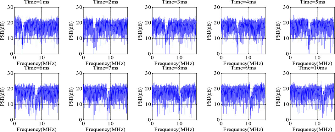
FIGURE 14. Spectral characteristics after anti-jamming based on timing reset (CFM).
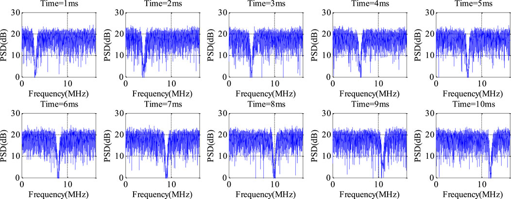
FIGURE 15. Spectral characteristics after anti-jamming based on timing reset (DFM).
Compared to Figures 8, 9, the experiment in this section shows that the spectrum has been significantly improved after anti-jamming, and only a null is formed at the interference frequency point, effectively protecting the signal energy and demonstrating an anti-jamming effect.
In the case of continuous frequency modulation and discontinuous frequency modulation interference, a time-domain-adaptive anti-jamming method based on timing reset is adopted. The time-frequency analysis was performed on the data after anti-jamming, and the results are shown in Figure 16 to describe the process of adaptive anti-jamming more clearly.
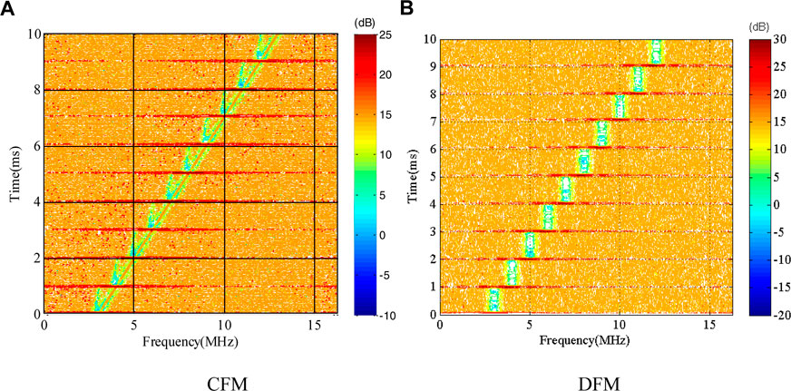
FIGURE 16. Analysis of time-frequency characteristics after anti-jamming based on timing reset. (A) CFM (B) DFM.
Compared to Figure 10, the method proposed in this paper only forms nulls around the interference frequency points, and the past interference will not affect the existing interference suppression for a long time, showing good anti-jamming performance.
In order to demonstrate the performance superiority of the improved algorithm more clearly, the time-frequency analysis and PSD nulling width after anti-jamming is demonstrated and compared with the proposed and traditional method. Under different discontinuous frequency modulation interference scenarios, the time-frequency analysis is shown in Figure 17, and the PSD nulling width is presented in Table 1. The interference bandwidth is 0.5 MHz, and the sweeping frequency speed is 1 MHz/ms. The null width of 10 m is continuously observed, and the timing reset period is 1 m.
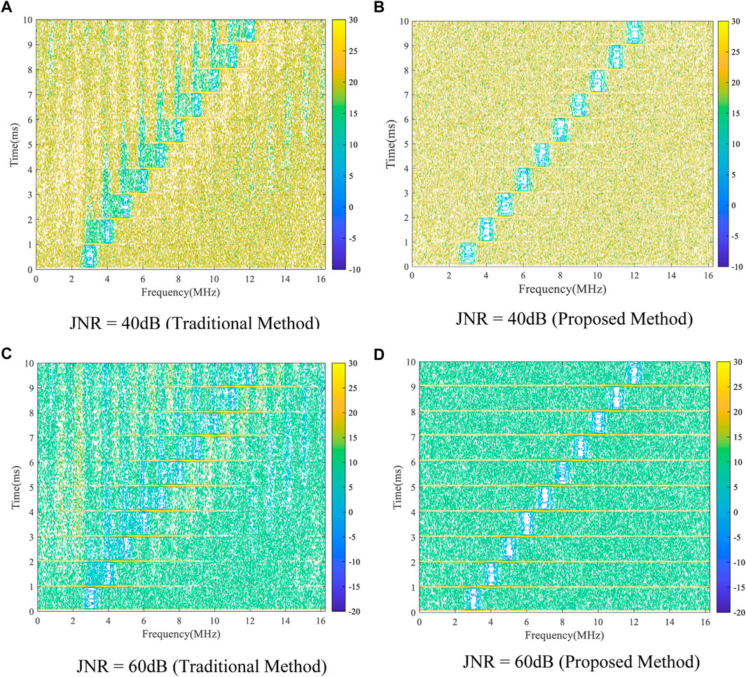
FIGURE 17. Time-frequency analysis performance comparison of different interference scenarios. (A) JNR = 40dB (Traditional Method) (B) JNR = 40dB (Proposed Method) (C) JNR = 60dB (Traditional Method) (D) JNR = 60dB (Proposed Method).
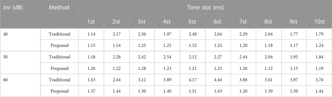
TABLE 1. Comparison of null width of different anti-interference methods.
The results in Figure 17 show that the interference power is inconsistent under different interference signal ratio conditions, but the anti-jamming performance of the proposed algorithm is always better than the traditional algorithm.
The results of Table 1 show that the PSD nulling width of discontinuous frequency modulation interference after traditional anti-interference fluctuates significantly, the maximum nulling width of which is up to 4.44 MHz. The nulling width of the improved algorithm is relatively stable, and the steady-state error is less than 0.2 MHz. It shows that the proposed algorithm only forms a null in the interference frequency band and will not reduce the navigation signal quality.
In traditional methods, when time-domain-adaptive anti-jamming faces sweeping-frequency interference, the frequency of the sweeping-frequency interference changes in real-time, and it is difficult for time-domain-adaptive anti-jamming to adapt to the frequency change. The time-domain-adaptive anti-jamming algorithm usually adopts the power invert criterion. When the frequency of the sweeping interference changes in real-time, the PSD nulling width after the anti-jamming increase, failing the time-domain-adaptive anti-jamming algorithm. According to the simulation experiment, the convergence time of the adaptive algorithm is negligible relative to the reception of the navigation signal, and the sweeping frequency interference affects the entire signal spectrum. The influence of sweeping-frequency interference on the signal spectrum is closely related to the timing reset time. In the simulation scenario of this paper, the influence time of the frequency sweep interference is less than 1 m, and the influence of the frequency sweep interference is compared to the traditional method, demonstrating a substantial reduction. Therefore, this paper proposes an anti-jamming method based on the filter timing reset, which can solve the problems caused by frequency sweep interference. The anti-interference null is always generated in the interference frequency band without affecting the navigation signal, significantly improving the anti-jamming performance of sweeping-frequency interference.
This paper proposes a time-domain-adaptive anti-jamming processing method for satellite navigation receivers in the context of the sweeping-frequency interference scenario. This method also solves the problem of sweeping-frequency interference causing the time-domain-adaptive anti-jamming method to fail. It is difficult for the traditional time-domain-adaptive anti-jamming method to adapt to the changes in sweeping-frequency interference. According to the problem of it being difficult for the traditional method to adapt to the change in the interference frequency, a time-domain-adaptive anti-jamming processing method based on the timing reset weight vector was designed. The analysis shows that a time-domain anti-jamming method based on the minimum power criterion cannot suppress sweeping-frequency interference. The simulation verification shows that it is difficult for the traditional method to suppress the sweeping-frequency interference, and even the anti-jamming weight coefficient is disordered. The anti-jamming processing method proposed in this paper reduces the problems caused by the change in the interference frequency. The carrier-to-noise ratio during simulation shows promising results and can improve the anti-jamming performance.
The raw data supporting the conclusions of this article will be made available by the authors, without undue reservation.
BL and JQ performed the theoretical study, conducted the experiments, processed the data and wrote the manuscript. ZL and XY designed the system, provided research suggestions and revised the manuscript. JS and BL helped in performing the experiments. XL provided the experiment equipment and suggestions for the manuscript. All authors have read and agreed to the published version of the manuscript.
This research was funded by the National Natural Science Foundation of China (No.62003354).
The authors would like to thank the editors and reviewers for their efforts to help the publication of this paper.
The authors declare that the research was conducted in the absence of any commercial or financial relationships that could be construed as a potential conflict of interest.
All claims expressed in this article are solely those of the authors and do not necessarily represent those of their affiliated organizations, or those of the publisher, the editors and the reviewers. Any product that may be evaluated in this article, or claim that may be made by its manufacturer, is not guaranteed or endorsed by the publisher.
1. Fan Z, Yang P, Mei C, Zhu Q, Luo X. Fast attitude estimation system for unmanned ground vehicle based on vision/inertial fusion. Machines (2021) 9:241. doi:10.3390/machines9100241
2. Mirmohammadian F, Asgari J, Verhagen S, Amiri-Simkooei A. Multi-GNSS-weighted interpolated tropospheric delay to improve long-baseline RTK positioning. Sensors (2022) 22:5570. doi:10.3390/s22155570
3. Camps A. Spatial resolution in GNSS-R under coherent scattering. IEEE Geosci Remote Sens Lett (2020) 17:32–6. doi:10.1109/LGRS.2019.2916164
4. Yi T-H, Li H-N, Gu M. Experimental assessment of high-rate GPS receivers for deformation monitoring of bridge. Measurement (2013) 46:420–32. doi:10.1016/j.measurement.2012.07.018
5. Liu Y, Zhou W, Ji B, Yu D, Bian S, Gu S, et al. Effect of stochastic modeling for inter-frequency biases of receiver on BDS-3 five-frequency undifferenced and uncombined precise point positioning. Remote Sens (Basel) (2022) 14:3595. doi:10.3390/rs14153595
6. Liu S, Yue J, Chu Z, Zhu S, Liu Z, Wu J. An improved snow depth retrieval method with adaptive noise reduction for GPS/GLONASS/Galileo/BDS multi-frequency signals. Meas Sci Technol (2022) 33:085011. doi:10.1088/1361-6501/ac62c9
7. Zhao H, Cheng C, Huang G, Li C, et al. Combining the tide gauge stations and GPS/GLONASS observations to validate global and regional ocean tide models around China coast. J Surv Eng (2022) 148. doi:10.1061/(ASCE)SU.1943-5428.0000396
8. Lu Z, Chen F, Xie Y, Sun Y, Cai H. High precision pseudo-range measurement in GNSS anti-jamming antenna array processing. Electronics (2020) 9:412. doi:10.3390/electronics9030412
9. Ni S, Ren B, Chen F, Lu Z, Wang J, Ma P, et al. GNSS spoofing suppression based on multi-satellite and multi-channel array processing. Front Phys (2022) 10. doi:10.3389/fphy.2022.905918
10. Huang X, Chen Y, Wang Y. Simulation of interference effects of UWB pulse signal to the GPS receiver. Discrete Dyn Nat Soc (2021) 2021:1–8. doi:10.1155/2021/9935543
11. Lu Z, Chen H, Chen F, Nie J, Ou G. Blind adaptive channel mismatch equalisation method for GNSS antenna arrays. IET Radar Sonar & Navigation (2018) 12:383–9. doi:10.1049/iet-rsn.2017.0416
12. Lu Z, Song J, Huang L, Ren C, Xiao Z, Li B. Distortionless 1/2 overlap windowing in frequency domain anti-jamming of satellite navigation receivers. Remote Sensing (2022) 14:1801. doi:10.3390/rs14081801
13. Lu Z, Nie J, Chen F, Ou G. Impact on anti-jamming performance of channel mismatch in GNSS antenna arrays receivers. Int J Antennas Propagation (2016) 2016:1–9. doi:10.1155/2016/1909708
14. Fante RL, Torres JA. Cancellation of diffuse jammer multipath by an airborne adaptive radar. IEEE Trans Aerosp Electron Syst (1995) 31:805–20. doi:10.1109/7.381927
15. Marathe T, Daneshmand S, Lachapelle G. Assessment of measurement distortions in GNSS antenna array space-time processing. Int J Antennas Propag (2016) 2:1–17. doi:10.1155/2016/2154763
16. Fante RL, Vaccaro JJ. Wideband cancellation of interference in a GPS receive array. IEEE Trans Aerosp Electron Syst (2000) 36:549–64. doi:10.1109/7.845241
17. Lu Z, Nie J, Wan Y, Ou G. Optimal reference element for interference suppression in GNSS antenna arrays under channel mismatch. IET Radar, Sonar Navigation (2017) 11.
18. Huo SM, Nie JW, Wang FX. Block-flow noise power estimation algorithm for pulsed interference detection of GNSS receivers. Electron Lett (2015) 51:1522–4. doi:10.1049/el.2015.1445
19. Huo SM, Nie JW, Tang XM, Wang FX. Minimum energy block technique against pulsed and narrowband mixed interferers for single antenna GNSS receivers. IEEE Commun Lett (2015) 19:1933–6. doi:10.1109/LCOMM.2015.2472516
20. Li XH, Chen FQ, Lu ZK, Liu Z, Ou G. Overview of anti-jamming technology based on GNSS single-antenna receiver. In: International Conference on Geoinformatics and Data Analysis; 1 July 2020; New York, NY, United States (2020). doi:10.1145/3397056.3397077
21. Zhou Q, Zheng H, Wu X, Yue X, Chen Z, Wang Q. Fractional fourier transform-based radio frequency interference suppression for high-frequency surface wave radar. Remote Sensing (2020) 12:75. doi:10.3390/rs12010075
22. Huang L, Lu Z, Xiao Z, Ren C, Song J, Li B. Suppression of jammer multipath in GNSS antenna array receiver. Remote Sens (Basel) (2022) 14:350. doi:10.3390/rs14020350
23. Kogon SM, Williams DB, Holder EJ. Exploiting coherent multipath for mainbeam jammer suppression. IEE Proc Radar Sonar Navig (1998) 145:303. doi:10.1049/ip-rsn:19982221
24. Yuantao G, Kun T, Huijuan C. LMS algorithm with gradient descent filter length. IEEE Signal Process Lett (2004) 11:305–7. doi:10.1109/lsp.2003.822892
25. Srar JA, Chung K, Mansour A. Adaptive array beamforming using a combined LMS-LMS algorithm. IEEE Trans Antennas Propag (2010) 58:3545–57. doi:10.1109/TAP.2010.2071361
26. Zhaoqing S, Yao C. Nonlinear adaptive direct generalized predictive control based on LS-SVR algorithm. In: 2012 International Conference on Industrial Control and Electronics Engineering; 03-05 March 2012; Xiamen (2012). p. 1543. doi:10.1109/ICICEE.2012.406
27. Djigan V. Some tricks of calculations in MIL RLS algorithm. In: 2021 23rd International Conference on Digital Signal Processing and its Applications (DSPA); 24-26 March 2021; Moscow, Russian Federation (2021). doi:10.1109/DSPA51283.2021.9535888
28. Slavakis K, Banerjee S. Robust hierarchical-optimization RLS against sparse outliers. IEEE Signal Process Lett (2020) 27:171–5. doi:10.1109/LSP.2019.2963188
29. Cattivelli FS, Sayed AH. Analysis of spatial and incremental LMS processing for distributed estimation. IEEE Trans Signal Process (2011) 59:1465–80. doi:10.1109/TSP.2010.2100386
30. Ghazanfari-Rad S, Labeau F. Formulation and analysis of LMS adaptive networks for distributed estimation in the presence of transmission errors. IEEE Internet Things J (2016) 3:146–60. doi:10.1109/JIOT.2015.2451220
31. Hinamoto Y, Sakai H. A filtered-X LMS algorithm for sinusoidal reference signals—effects of frequency mismatch. IEEE Signal Process Lett (2007) 14:259–62. doi:10.1109/LSP.2006.884901
32. Shi K, Ma X. A frequency domain step-size control method for LMS algorithms. IEEE Signal Process Lett (2010) 17:125–8. doi:10.1109/LSP.2009.2032996
33. Jalal B, Yang X, Liu Q, Long T, Sarkar TK. Fast and robust variable-step-size LMS algorithm for adaptive beamforming. IEEE Antennas Wirel Propag Lett (2020) 19:1206–10. doi:10.1109/LAWP.2020.2995244
34. Kim KY, Lee SH, Lee SW, Shin Y. Multiple linear chirp-based partial-band chirp jamming for chirp spread spectrum systems. In: International Conference on Information and Communication Technology Convergence (ICTC); 16-18 October 2019; Jeju, Korea (South) (2019). p. 1088–90. doi:10.1109/ICTC46691.2019.8939918
35. Wei Z, Fu N, Jiang S, Li X, Qiao L. Parameter measurement of LFM signal with FRI sampling and nuclear norm denoising. IEEE Trans Instrum Meas (2022) 71:71–17. doi:10.1109/TIM.2022.3158986
36. Mei M, Yu Z, Wu Y, Yu S. A new approach for suppressing sidelobe by decomposing chirp signal in CFM space. In: 2017 IEEE International Geoscience and Remote Sensing Symposium; 23-28 July 2017; Fort Worth, TX, USA (2017). p. 2361–4. doi:10.1109/IGARSS.2017.8127465
37. Tam WC, Blanton S. Design-for-Manufacturability assessment for integrated circuits using RADAR. IEEE Trans Comput -Aided Des Integr Circuits Syst (2014) 33:1559–72. doi:10.1109/TCAD.2014.2336216
38. Qin W, Gamba MT, Falletti E, Dovis F. An assessment of impact of adaptive notch filters for interference removal on the signal processing stages of a GNSS receiver. IEEE Trans Aerosp Electron Syst (2020) 56:4067–82. doi:10.1109/TAES.2020.2990148
39. Huang L, Lu Z, Ren C, Liu Z, Xiao Z, Song J, et al. Research on detection technology of spoofing under the mixed narrowband and spoofing interference. Remote Sens (Basel) (2022) 14:2506. doi:10.3390/rs14102506
40. Song J, Lu Z, Xiao Z, Li B, Sun G. Optimal order of time-domain adaptive filter for anti-jamming navigation receiver. Remote Sens (Basel) (2022) 14:48. doi:10.3390/rs14010048
41. Lu Z, Nie J, Chen F, Chen H, Ou G. Adaptive time taps of STAP under channel mismatch for GNSS antenna arrays. IEEE Trans Instrum Meas (2017) 66:2813–24. doi:10.1109/tim.2017.2728420
42. Vanamadi R, Kar A, Burra S, Anand A, Majhi B. Convergence performance evaluation of MSF-based LMS adaptive algorithm. In: 2019 16th International Conference on Electrical Engineering/Electronics, Computer, Telecommunications and Information Technology (ECTI-CON); 10-13 July 2019; Pattaya, Thailand (2019). p. 597–600. doi:10.1109/ECTI-CON47248.2019.8955136
43. Murmu G, Nath R. Convergence performance comparison of transform domain LMS adaptive filters for correlated signal. In: 2011 International Conference on Devices and Communications; 24-25 February 2011; Mesra, India (2011). doi:10.1109/ICDECOM.2011.5738534
Keywords: global position systems (GPS), sweep interference, time domain adaptive anti-jamming, timing reset, adaptive filer
Citation: Li B, Qiao J, Lu Z, Yu X, Song J, Lin B and Li X (2023) Influence of sweep interference on satellite navigation time-domain anti-jamming. Front. Phys. 10:1063474. doi: 10.3389/fphy.2022.1063474
Received: 07 October 2022; Accepted: 02 December 2022;
Published: 09 January 2023.
Edited by:
Siming Liu, Southwest Jiaotong University, ChinaReviewed by:
Youfeng Cheng, Southwest Jiaotong University, ChinaCopyright © 2023 Li, Qiao, Lu, Yu, Song, Lin and Li. This is an open-access article distributed under the terms of the Creative Commons Attribution License (CC BY). The use, distribution or reproduction in other forums is permitted, provided the original author(s) and the copyright owner(s) are credited and that the original publication in this journal is cited, in accordance with accepted academic practice. No use, distribution or reproduction is permitted which does not comply with these terms.
*Correspondence: Zukun Lu, bHV6dWt1bkBudWR0LmVkdS5jbg==; Xiaoyou Yu, eXV4aWFveW91QGhudS5lZHUuY24=
Disclaimer: All claims expressed in this article are solely those of the authors and do not necessarily represent those of their affiliated organizations, or those of the publisher, the editors and the reviewers. Any product that may be evaluated in this article or claim that may be made by its manufacturer is not guaranteed or endorsed by the publisher.
Research integrity at Frontiers
Learn more about the work of our research integrity team to safeguard the quality of each article we publish.