
94% of researchers rate our articles as excellent or good
Learn more about the work of our research integrity team to safeguard the quality of each article we publish.
Find out more
ORIGINAL RESEARCH article
Front. Phys., 25 November 2022
Sec. Optics and Photonics
Volume 10 - 2022 | https://doi.org/10.3389/fphy.2022.1058240
This article is part of the Research TopicOptical Wave Propagation and Communication in Turbulent MediaView all 7 articles
A fixed high-power laser system used as an aerospace defense weapon has limitations such as the transmitter size, serious thermal blooming during propagation, rapid motion, and the variation of the location of the target. In the present paper, we propose a method by arranging many high-power systems with adequate distance in a defense area. The intensity distribution and the energy irradiated on the target are studied and compared with a fixed laser system. Results show that adequate arrangement of many high-power laser systems can reply to the arbitrary and rapid motion of the target.
In today’s world, aerospace defense has become more important and complex accompanied by the development of hypersonic missiles [1, 2]. High-power lasers are considered one of the most promising methods due to the energy travels with the speed of light [2, 3]. However, the output power of the laser and the effect of the atmosphere are the major barriers of high-power lasers used as the aerospace defense weapon [4, 5].
Since coherent beam combining (CBC) is more complex and expensive, incoherent beam combining (IBC) is regarded as the major method to increase the output power of the transmitter in the application of the laser weapon [6–11]. There are two factors that will hinder the application of IBC in aerospace defense. One factor is the size of the transmitter. When we use a transmitter to send the combined beams, the size of the aperture will limit the channels of the beam. Another factor is that further increasing the output power of the combined beams will result in serious nonlinear effects [12–14].
In the present paper, we propose a new aerospace defense method by combining laser beams apart from a long distance.
The propagation of incoherent combination of different location beams is shown in Figure 1. There are many laser beams located in different locations. All the laser beams are transmitted to the same target.
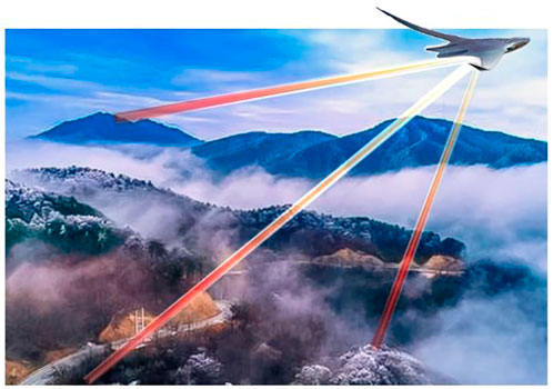
FIGURE 1. Propagation schematic representation of the incoherent beams by combining different location beams.
There are many factors that will affect the propagation, such as the wavelength, size of the transmitter, the distance between each laser, and the propagation distance [4, 15]. In practice, the target moves in a very high speed which will cause the change of the propagation distance, as shown in Figure 2. P denotes the location of the target which moves in a velocity v. Q is the location of one laser source.
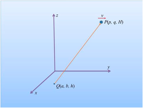
FIGURE 2. Variation of the distance between the target and the beams due to the motion of the target.
We can see from Figure 2 that the distance between the beam and the target is
where (a, b, h) and (p, q, H) are the coordinates of the beam and the target, respectively. In addition to the propagation distance, the zenith angle of propagation also affects the destructive effect, as shown in Figure 3.
From Figures 2, 3 we can see that the direction of beam is
where (α, β, γ) are the direction angles of the beam. If we assume that the surface irradiated by the laser is
where
In practice, laser beams need a period of time to damage the target. The energy of the laser irradiating on the target can be expressed as
where T is the time of the irradiation of the laser on the target. From Eqs 3, 4, we can see that
Absorption, scattering, turbulence, and thermal blooming of the atmosphere will affect the propagation of the laser beam in free space [16]. In the present paper, only the effect of turbulence is considered. For simplicity, we assume that the beam has a Gaussian intensity distribution. Thus, the initial optical field at the arbitrary location is denoted as [17]
where P is the power of the beam, w0, the waist width, (am, bm), the location of the laser beam, and (x0, y0), the coordinates of the initial plane perpendicular to the propagation direction. The intensity distribution at the target can be calculated by [18]
where
is the coordinate conversion, and
and
where
is the coherence length vertical from the ground to the altitude H [20], and
where
The total average intensity of the incoherent combining beam at the target is the sum of the average intensity of each laser radiating on the target.
To analyze the performance of the aerospace defense method, the special case is given as follows.
To compare the damage effect of the incoherent beams, the power levels are evaluated by using the total average intensity of the incoherent combining beam at the target, which is the sum of the average intensity of each laser radiating on the target. The average intensity of each laser is expressed in Eq. 11, where P is a constant.
For simplicity, we assume h = 0, namely, all of the laser sources are located at the ground, as shown in (Figure 4). The coordinates of the laser sources are Q11 (-a, -a), Q12 (0, -a), Q13 (a, -a), Q21 (-a, 0), Q22 (0, 0), Q23 (a, 0), Q31 (-a, a), Q32 (0, a), and Q33 (a, a). The coordinate of the target is p = p0 + vt and q = 0, and the altitude is H. For calculation, we set a = 10 km, p0 = –50 km, v = 300 m/s, and H = 10 km.
In this paper, we select the ITU-R model presented in 2001 to describe the model of the altitude-dependent structure constant.
where
For comparison, we assume that the power of each laser is P when all of the nine lasers are sent to the target together. Even though, the spot of the laser maybe an ellipse, in practice, we only concern a certain area. We assume the area is a circle with the radius R = 0.1 m. If only one laser is sent to the area, we assume the output power of the laser is 9P. Figure 5 shows the variation of the energy in the area of the circle with the irradiated time. It should be noted that the ratio of energy to power expresses the damage ability of the incoherent beam on the area S of the target and has the unit of time when the power of these lasers is a constant.
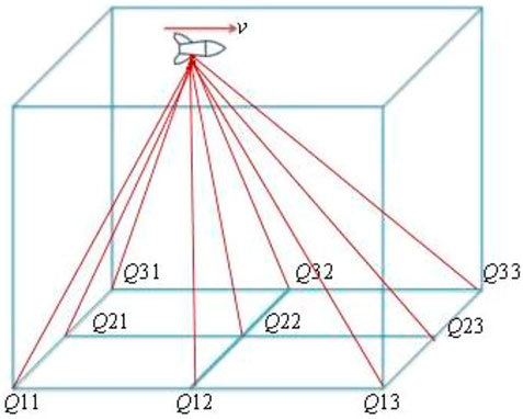
FIGURE 4. Special case for analyzing the performance of the aerospace defense method, where Q11 to Q33 denote nine laser sources and the target moves horizontally in a uniform velocity.
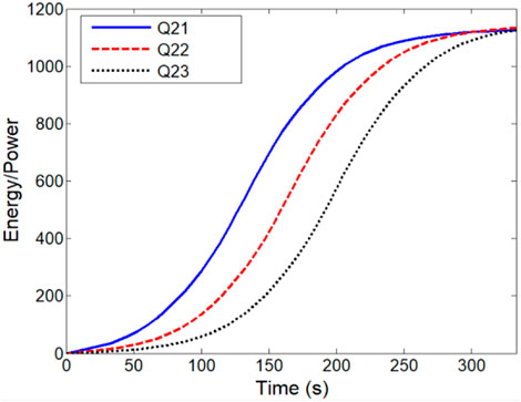
FIGURE 5. Variation of the energy in the irradiated area with the irradiated time for lasers Q21, Q22, and Q23, respectively.
Because Q21 is in the front of the three lasers, the energy increases fast at the start. The energy increases slowly when the target is far apart from the laser. With the increase in the angle of elevation, the growth rate of the energy becomes fast and keeps a period of time. This period of time is the optimum irradiated time. The energy irradiated by Q22 and Q23 has the same variation. Figure 6 gives the variation of the energy in the area irradiated by lasers Q11, Q12, and Q13, respectively.
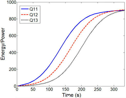
FIGURE 6. Variation of the energy in the irradiated area with the irradiated time for lasers Q11, Q12, and Q13, respectively.
Comparing with Figure 5, we can see that the variation of the energy irradiated by lasers Q11, Q12, and Q13 has the same trend as in Figure 5. Because the trajectory of the target is just above the line determined by Q21, Q22, and Q23, namely, the angle of elevation for Q21, Q22, and Q23 is larger than that for Q11, Q12, and Q13, the total energy irradiated by Q21, Q22, and Q23 at the same time is larger than that by Q11, Q12, and Q13, respectively.
In application, it is difficult for letting a laser just under the trajectory of the target. Arrays of many lasers can solve the problem of the target moving in the arbitrary trajectory. Figure 7 shows the comparison between variation of the energy irradiated by one laser or by all of the lasers. We assume the power of each laser is P when all of the lasers irradiate the target together. Thus, the total power of all the lasers also is 9P. The energy irradiated on the target is expressed by Q. The power of one laser is 9P if only one laser irradiates the target.
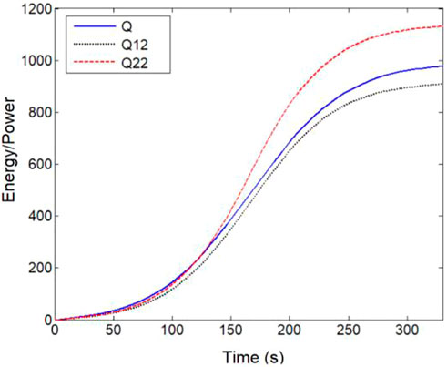
FIGURE 7. Comparison between the variation of the energy irradiated by only one laser and all of the lasers, where Q denotes the energy irradiated on the target by all lasers.
It can be seen that the effect of irradiation by the laser array is better than that only by Q12 and is worse than that only by Q22. When the target is far from the laser, namely, the angle of elevation is small, the effect of the irradiation has little difference between the lasers Q, Q12, and Q22.
It is important and difficult for the aerospace defense duo to the complex trajectory and very fast velocity of the target. Not only the power of one laser system is hard to satisfy the requirement but also its propagation distance and the variation of the angle of elevation will hinder the performance, even though the laser system is fixed in a moving device.
Arranging the laser system with an adequate distance can solve the problem of aerospace defense by using high-power laser systems. No matter what location the targets come from, there are several high-power laser systems with effective operating distance. Results show that these arrangements of laser systems take many advantages over a fixed laser.
The raw data supporting the conclusions of this article will be made available by the authors, without undue reservation.
XC developed the concept, and KL and ZL performed the numerical simulations.
This research was supported by the State Key Laboratory of Pulsed Power Laser Technology Foundation (SKL2021KF02).
Authors KL and ZW were employed by the companies China Electronics Technology Information Industry Co., Ltd., and The 27th Research Institute of China Electronics Technology Group Corporation.
The remaining author declares that the research was conducted in the absence of any commercial or financial relationships that could be construed as a potential conflict of interest.
All claims expressed in this article are solely those of the authors and do not necessarily represent those of their affiliated organizations, or those of the publisher, the editors, and the reviewers. Any product that may be evaluated in this article, or claim that may be made by its manufacturer, is not guaranteed or endorsed by the publisher.
1. Bankman IN, Rogala EW, Pavek RE. Laser radar in ballistic missile defense. Johns Hopkins Apl Tech Dig (2001) 22:379–93.
2. Syed AA, Mohsin M, Ali S. Survey and technological analysis of laser and its defense applications. Defence Tech (2021) 17:583–92. doi:10.1016/j.dt.2020.02.012
3. Jung M, Riesbeck T, Schmitz J, Baumgärtel T, Ludewigt K, Graf A. High energy laser demonstrators for defense applications. In: Proc. SPIE 10254, XXI International Symposium on High Power Laser Systems and Applications 1025416 (2016).
4. Burlamacchi P, Consortini A, Ronchi L, Francia GTD. Laser beam propagation in the atmosphere. IEEE J Quan Electron (1967) 3:259. doi:10.1109/jqe.1967.1074506
5. Li X, Cheng Z, Jiang J, Xu G, Shi H, Zhao Q. Focus characteristics of laser beam for long distance propagation in atmosphere. Acta Optica Sinica (2001) 03:324–9.
6. Sprangle P, Ting A, Penano J, Fischer R, Hafizi B. Incoherent combining and atmospheric propagation of high-power fiber lasers for directed-energy applications. IEEE J Quan Electron (2008) 45:138–48. doi:10.1109/jqe.2008.2002501
7. Fan TY. Laser beam combining for high-power, high-radiance sources. IEEE J Sel Top Quan Electron (2005) 11:567–77. doi:10.1109/jstqe.2005.850241
8. Leger JR, "Fundamentals of coherent and incoherent beam combining," In Proceedings of SPIE - The International Society for Optical Engineering (2006).
9. Pu Z, Liu Z, Wang X, Ma Y, Ma H, Xu X. Coherent beam combining of two fiber amplifiers using stochastic parallel gradient descent algorithm. Opt Laser Tech (2009) 41:853–6. doi:10.1016/j.optlastec.2009.03.002
10. Wirth C, Schmidt O, Tsybin I, Schreiber T, Jung M, Bruckner F, et al. 2 kW incoherent beam combining of four narrow-linewidth photonic crystal fiber amplifiers. Opt Express (2009) 17:1178–83. doi:10.1364/oe.17.001178
11. Ma P, Zhou P, Ma Y, Su R, Liu Z. Coherent polarization beam combining of four fiber amplifiers in 100 ns pulsed-regime. Opt Laser Tech (2013) 47:336–40. doi:10.1016/j.optlastec.2012.08.030
12. Gebhardt FG. Twenty-five years of thermal blooming - an overview. Proc SPIE - Int Soc Opt Eng (1990) 2–25.
13. Sheldon SJ, Knight LV, Thorne JM. Laser-induced thermal lens effect: A new theoretical model. Appl Opt (1982) 21:1663–9. doi:10.1364/ao.21.001663
14. Ding Z, Li X, Cao J, Ji X. Influence of thermal blooming on the beam quality of an array of Hermite–Gaussian beams propagating in the atmosphere. Appl Opt (2020) 59:10944. doi:10.1364/ao.405980
15. Chu X, Sun Q, Wang J, Lu P, Xie W, Xu X. Generating a Bessel-Gaussian beam for the application in optical engineering. Sci Rep (2016) 5:18665. doi:10.1038/srep18665
17. Chu X, Liu Z, Wu Y. Propagation of a general multi-Gaussian beam in turbulent atmosphere in a slant path. J Opt Soc Am A (2008) 25:74–9. doi:10.1364/josaa.25.000074
18. Yura HT, Hanson SG. Optical beam wave propagation through complex optical systems. J Opt Soc Am A (1987) 4:1931–48. doi:10.1364/josaa.4.001931
19. Tyson RK, Wizinowich PL. Principles of adaptive optics. Phys Today (1992) 45:100. doi:10.1063/1.2809540
Keywords: combining beams, aerospace defense, turbulent atmosphere, high-power laser, incoherent beam combination
Citation: Liao K, Liu Z and Chu X (2022) Combining beams in different locations for aerospace defense in a turbulent atmosphere. Front. Phys. 10:1058240. doi: 10.3389/fphy.2022.1058240
Received: 30 September 2022; Accepted: 08 November 2022;
Published: 25 November 2022.
Edited by:
Fei Wang, Soochow University, ChinaReviewed by:
Chaoliang Ding, Luoyang Normal University, ChinaCopyright © 2022 Liao, Liu and Chu. This is an open-access article distributed under the terms of the Creative Commons Attribution License (CC BY). The use, distribution or reproduction in other forums is permitted, provided the original author(s) and the copyright owner(s) are credited and that the original publication in this journal is cited, in accordance with accepted academic practice. No use, distribution or reproduction is permitted which does not comply with these terms.
*Correspondence: Xiuxiang Chu, Y2h1eGl1eGlhbmdAYWxpeXVuLmNvbQ==
Disclaimer: All claims expressed in this article are solely those of the authors and do not necessarily represent those of their affiliated organizations, or those of the publisher, the editors and the reviewers. Any product that may be evaluated in this article or claim that may be made by its manufacturer is not guaranteed or endorsed by the publisher.
Research integrity at Frontiers

Learn more about the work of our research integrity team to safeguard the quality of each article we publish.