 Dianyuan Miao1
 Junjie Hu
 Jianbo Zhang
- 1CNOOC EnerTech-Drilling & Production Co., Tianjin, China
- 2School of Petroleum Engineering, China University of Petroleum (East China), Qingdao, China
A dynamic shut-in procedure is commonly adopted after a kick incident in order to build up the wellbore pressure, obtain reservoir information, and thereby handle the gas kick. In deep-water scenarios, the hydrate growth behaviors have a significant effect on gas migration and interphase mass transfer, which has not been quantitatively analyzed during the well shut-in process. In this study, a comprehensive mechanistic model of wellbore dynamics is developed considering gas migration and phase transitions. The simulation results show that the wellbore pressure field can be built up in different trends during different well shut-in periods, governed by gas seepage from the reservoir and gas migration along the wellbore, respectively. Masking the migration of free gas, the phase transition phenomena have a significant influence on the wellbore dynamics and bottomhole pressure. This work adds further insights into quantitatively characterizing the hydrate growth behaviors and interphase mass transfer rules of gas bubbles during a dynamic well shut-in procedure.
1 Introduction
As a gas kick occurs in deep-water drilling, uncontrolled gas migration can greatly threaten the flow assurance in the wellbore [1]. The well shut-in procedure is commonly conducted as rapidly as possible to stop the formation from flowing, reduce the risk of fracturing the casing shoe, and secure the well. Moreover, the pressure build-up process during a dynamic shut-in procedure is somewhat similar to the pressure transient analysis, which implies the early response of reservoir behaviors and the flow regime [2]. During a well shut-in procedure, estimates can be made of the formation pressure and the influx information, of which accuracy is vital to the success of the following well control operations [3].
Generally, the variation of the wellbore pressure during a well shut-in process is driven by two mechanisms of gas migration: 1) the continuing influx enters the closed system of wellbore fluids due to the pressure underbalance at the open-hole section, and 2) the gas bubbles in the wellbore ascend continuously due to the buoyancy. At present, the theoretical and experimental research studies indicated that the surface pressures are carried upward by a complicated flow process, which is closely related to the influx type and size, reservoir characteristics, fluid rheology and compressibility, well expansion, and fluid loss [4–7]. Particularly, the preliminary analysis revealed that gas dissolution has an important influence on pressure build-up behaviors [6, 8]. This is because the free gas goes into the solution in the drilling fluid and there is no further gas migration, as a kind of phase transition phenomenon. Interestingly, it can be expected that the free gas will convert into solid hydrates affected by the low temperature and high pressure in deep-water drilling [9–11]. Recently, several studies have been performed to analyze the effect of phase transition on the wellbore flow [12–14]. Fu et al. [15–17] showed a new insight into multiphase flow modeling and proposed a novel pressure loss prediction model for the multiphase flow in the wellbore and pipeline based on the energy dissipation theory. The accuracy of the developed model is significantly enhanced by coupling it with the methane hydrate formation model and the hydrate slurry rheology model and reveals the effects of phase transition on the pressure loss of the multiphase flow [14, 17, 18].
The dynamic interphase mass transfer during gas dissolution and hydrate growth may mask the early response of the pressure build-up and gas influx. Considering the reservoir coupling and gas slippage in the wellbore, Billingham et al. [2] and Ren et al. [7] have developed pioneering models to describe the variations of the bottomhole pressure during a well shut-in procedure. However, in these models, the distribution of free gas is simplified, namely, the gas influx is assumed to fill the annulus and exist as a single bubble/continuous slug during its upward migration, which was revealed to be invalid [5]. Therefore, the characteristics of a pressure build-up can be overestimated since the migration of free gas was simplified, and the phase transitions were neglected. Therefore, a novel wellbore dynamic model considering the flow regime and phase transition effects is necessary to help drilling engineers obtain a thorough understanding of the kick evolution mechanism and the wellbore pressure build-up characteristics.
2 Model development
Although the kicking well is shut in, the gas can continuously flow into the semi-closed wellbore driven by the pressure underbalance and the difference in the densities of the gas and liquid. Gas migration, accompanied by the increase in the wellbore pressure, can compress the wellbore and fluid and promote the rates of gas dissolution and hydrate phase transition. In turn, the pressure field updates gradually through the synergistic action of multiple factors. Therefore, the build-up of surface pressure can be closely related to reservoir coupling, bubble rise, phase transition of the fluid, wellbore compressibility, etc. In this regard, it usually takes a long period for the surface pressure to stabilize. The potential reasons affecting the variation of wellbore pressure can be as follows:
1) Reservoir coupling. There exists the mass exchange between the wellbore and reservoir at the open-hole section. Gas enters the wellbore due to pressure underbalance, whereas the drilling fluid can filter into the formation as the bottomhole pressure exceeds the reservoir pressure.
2) Wellbore compressibility. The drilling fluid usually has enough compressibility that the elasticity of the wellbore should be considered.
3) Gas expansion. The gas bubbles expand gradually as they ascend in the wellbore.
4) Gas dissolution. The gas influx can be dissolved in the drilling fluid, which masks the early response of the gas kick.
5) Hydrate phase transition. The free gas can convert into solid hydrates, accompanied by variations of phase volumes.
2.1 Pressure variation in a semi-closed wellbore
In the semi-closed wellbore, the flow dynamic is significantly unsteady and is affected by gas migration. Considering volume conservation, the following equation can be obtained [9]:
where Qg is the gas influx rate at the open-hole section, which can be estimated using a transient reservoir model [19], m3/s; Qloss is the static filtration rate of the drilling fluid, m3/s; ∆t is the time interval, s; Vw is the volume of the wellbore, m3; Cw is the compressibility coefficient of the wellbore, 1/Pa; Pw is the bottomhole pressure, Pa; t is the well shut-in time, s; i is the segment number, 0 ≤ i ≤ N; mgi is the mass of the free gas in segment i of the wellbore, kg; Mg is the molecular mass of the gas, kg/mol; Mw is the molecular mass of water, kg/mol; Nh is the hydration number, and Nh = 5.75 for methane hydrate; ∆mhi is the hydrate growth rate in segment i of the wellbore, kg; ∆msoli is the gas dissolution rate in segment i of the wellbore, kg; ρg is the gas density, kg/m3; hi is the depth of segment i, m; vg is the gas rise velocity, m/s; ρh is the hydrate density, kg/m3; ρsoli is the density of the dissolved gas in segment i, kg/m3; ELi is the volume of the drilling fluid in segment i of the wellbore, m3; CL is the compressibility of the drilling fluid, 1/Pa; and Pfi is the fluid pressure in segment i of the wellbore, Pa.
In Eq. 1, the terms on the left-hand side represent the gas influx, fluid loss, and wellbore expansion, respectively, while the terms on the right-hand side represent the gas expansion, hydrate growth, gas dissolution, and compressibility of the drilling fluid.
In order to obtain an accurate pressure profile along the wellbore, it is necessary to estimate the interphase mass transfer rates during gas migration.
2.2 Phase transition rates
The previous studies in the literature indicated that the gas hydrate can form and cover the gas bubble as it rises in the wellbore [20–23]. Formed on the bubble surface, the hydrate shell can reduce the gas dissolution rate and bubble rise velocity. Furthermore, the hydrate growth rate is governed by the mass transport processes of gas and water molecules through the shell, as shown in Figure 1.
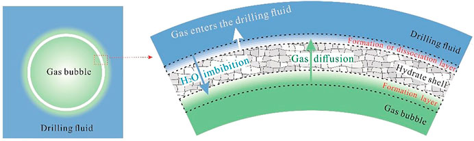
FIGURE 1. Schematic representation of hydrate shell growth on the bubble surface (adapted from Sun et al. [22]).
2.2.1 Gas dissolution
According to the diffusion theory, the gas dissolution rate is dominated by the mass transfer coefficient and unsaturation of the dissolved gas. Considering the aggregating state of the gas hydrate at the gas/liquid interface, Sun et al. [20] developed a gas dissolution model for a hydrated bubble.
where Nb is the number of gas bubbles in a segment of the wellbore; R is the bubble radius, m; δ is the thickness of the hydrate shell, m; Cins is the gas solubility at the hydrate/liquid interface, m3/m3; C∞ is the gas concentration in the liquid bulk, m3/m3; Dg is the gas diffusion coefficient in the liquid, m2/s; Jk is the gas dissolution rate on the outside of the hydrate shell, m3/s; and vg is the bubble rise velocity, m/s.
The gas dissolution can be significantly reduced by hydrate formation. On one hand, the occurrence of the hydrate phase can disturb the previous gas/liquid equilibrium state, and the gas solubility is decreased in the presence of a gas hydrate. On the other hand, as the hydrate shell thickens at the gas/liquid interface, the bubble rise velocity is reduced and the internal circulation is prevented, which leads to the decrease in the mass transfer coefficient [24].
In Eq. 3, the gas dissolution coefficient is closely related to the gas migration velocity. Considering the steady motion state of the hydrated bubble, the expression of the bubble rise velocity can be obtained [25]:
where CD is the drag coefficient, which is affected by the flow behaviors of gas bubbles and the properties of fluids. As for the migration of gas bubbles in the non-Newtonian drilling fluid, we proposed an empirical model based on the laboratory experiment of bubble rise [26].
where Re is the terminal Reynolds number of a gas bubble.
2.2.2 Hydrate growth
The previous experimental research indicated that the hydrate shell covering the bubble surface can prevent the direct contact between the gas and liquid. It means that the mass transfer across the shell becomes the dominant mechanism for continuous hydrate growth [27]. Considering the structure of hydrate crystals and the pore-throat properties of the hydrate shell, a unified model for dynamic hydrate shell growth on the bubble surface was developed by Sun et al. [20]:
where Jperm and Jdiff are the rates of water imbibition and gas diffusion through the hydrate film, m3/s.
where σ is the water/gas interfacial tension, N/m; μw is the viscosity of water, Pa∙s; Dh is the gas diffusion coefficient in the hydrate shell, m2/s; Ci is the gas concentration on the inner surface of the hydrate shell, m3/m3; and Co is the gas concentration on the outer surface of the hydrate shell, m3/m3.
3 Results and analysis
Using the proposed model, the variation rules of the pressure build-up and phase volumes are simulated and analyzed. The basic simulation parameters are shown in Table 1.
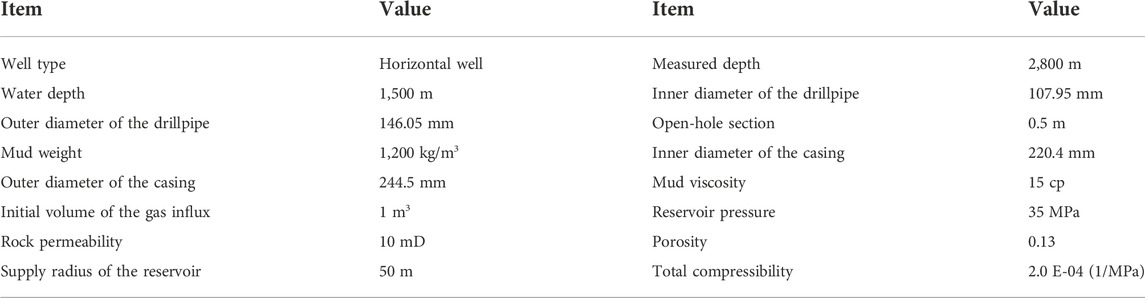
TABLE 1. Basic simulation parameters.
3.1 Analysis of the well shut-in procedure
Figure 2 shows the bottomhole pressure at different times. As seen, variations of the bottomhole pressure can be divided into two periods.

FIGURE 2. Variations of the bottomhole pressure throughout the well shut-in process.
At the early time of the well shut-in process, the reservoir gas percolates into the wellbore and the fluid pressure increases. In this period, the bottomhole pressure rapidly approaches the reservoir pressure driven by the continuous gas influx. At about 200 s, the reservoir pressure can be estimated by the pressure build-up curve.
At the later period of the well shut-in process (t > 200 s), the slippage of gas bubbles can be the dominant factor for wellbore dynamics, and the bottomhole pressure increases gradually. However, the pressure field changes more gently than that in the first period. It can be expected that the bottomhole pressure will increase continuously, and there is the risk of fracturing the casing shoe if the well cannot be shut in as rapidly as possible and the initial volume of gas influx is large.
3.2 Effect of phase transition
Figure 3 shows the variations of mass and volume of different phases. Commonly, the mass of free gas is governed by reservoir coupling and phase transitions. It increases rapidly in early time because the gas influx enters the wellbore continuously when the bottomhole pressure is less than the formation pressure. Subsequently, due to gas dissolution and hydrate growth, the mass of free gas decreases gradually as gas bubbles ascend. Furthermore, the volume of the free gas decreases gradually with time because the gas bubbles are compressed, affected by the increase in the wellbore pressure, and accompanied by conversion into other phases.
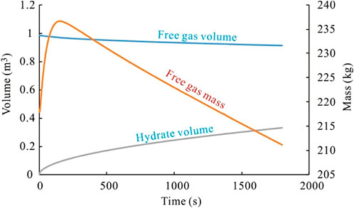
FIGURE 3. Volume and mass of the gas and hydrate phases in the wellbore.
In the hydrate phase stability field, the hydrates will grow on the bubble surface. In this regard, the volume of the gas hydrate increases gradually with time. It should be noted that gas dissolution and hydrate formation can significantly mask the migration of the gas influx and the build-up of the surface pressure.
Figure 4 shows the influence of phase transitions on variations in the surface pressure. As seen, the pressure can be overestimated if the phase transition effects are neglected. This is because a part of the free gas which compresses the wellbore and liquid will dissolve into the drilling fluid and convert to solid hydrates.
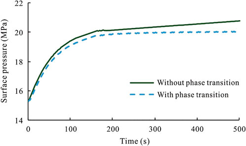
FIGURE 4. Comparison of surface pressures considering phase transitions or not.
4 Conclusion
In this study, we proposed a novel wellbore dynamic model for predicting the behaviors of bubble migration and the pressure build-up during a dynamic shut-in procedure in deep-water drilling. In the model, the mechanism of the interphase mass transfer during gas dissolution and hydrate growth is considered. The proposed model is applied to a field well, and the following general conclusions are drawn from the simulation analysis:
1) During a dynamic well shut-in procedure, the build-up process of the wellbore pressure can be divided into two periods. It first increases rapidly, affected by reservoir coupling, and then increases slightly, affected by gas slippage in the wellbore. Special attention should be paid to the risk of fracturing the casing shoe when the initial volume of the gas influx is large.
2) The pressure build-up process can be significantly overestimated if the phase transitions are neglected. However, the development of the gas kick may be masked due to the interphase mass transfer. There also exists the probability that the free gas will evolve and increase the wellbore pressure.
Data availability statement
The original contributions presented in the study are included in the article/Supplementary Material; further inquiries can be directed to the corresponding author.
Author contributions
DM: conceptualization, investigation, formal analysis, and writing—original draft; JH: data curation and writing—original draft; JZ: visualization and investigation; JW: resources, supervision; XS: conceptualization, funding acquisition, resources, supervision, and writing—review and editing.
Funding
This work was supported by the National Natural Science Foundations of China (52104056, U21B200505), the National Key Research and Development Program of China (2021YFC2800803), and the Natural Science Foundation—Youth Foundation in Shandong province (ZR2021QE155).
Conflict of interest
DM was employed by CNOOC EnerTech-Drilling & Production Co.
The remaining authors declare that the research was conducted in the absence of any commercial or financial relationships that could be construed as a potential conflict of interest.
Publisher’s note
All claims expressed in this article are solely those of the authors and do not necessarily represent those of their affiliated organizations, or those of the publisher, the editors, and the reviewers. Any product that may be evaluated in this article, or claim that may be made by its manufacturer, is not guaranteed or endorsed by the publisher.
References
1. Sun X, Sun B, Zhang S. A new pattern recognition model for gas kick diagnosis in deepwater drilling[J]. J Pet Sci Eng (2018) 167:418–25. doi:10.1016/j.petrol.2018.04.035
2. Billingham J, Thompson M, White DB. Advanced influx analysis gives more information following a kick [C]. In: SPE/IADC Drilling Conference; 22-25 February(1993); Amsterdam, Netherlands (1993). SPE-25710-MS.
3. Sun X, Liao Y, Wang Z, Zhao X, Sun B. Modelling of formation pore pressure inversion during tight reservoir drilling. Geofluids (2021) 2021:6626381–11. doi:10.1155/2021/6626381
4. Lage ACVM, Nakagawa EY, Cordovil AGDP. Experimental tests for gas kick migration analysis [C]. In: SPE-26953-MS, SPE Latin America/Caribbean Petroleum Engineering Conference; 27-29 April, 1994; Buenos Aires, Argentina (1994).
5. Matthews JL, Bourgoyne AT. Techniques for handling upward migration of gas kicks in a shut-in well [C]. In: SPE-11376-MS, IADC/SPE Drilling Conference; February 20-23, 1983; New Orleans: Louisiana (1983).
6. Guner S, Elshehabi T, Bilgesu I. The effects of gas kick migration on wellbore pressure [C]. In: Aade National Technical Conference and Exhibition Held at the Hilton Houston North Hotel; Houston, Texas, April 11–12, 2017 (2017).
7. Ren M, Li X, Liu S, Wang Y. Characteristics of wellbore pressure change during shut-in after blowout [J]. J China Univ Pet (2015) 39(3):113–9. (in Chinese). doi:10.3969/j.issn.1673-5005.2015.03.015
8. Schilhab LC, Rezmer IM. Factors affecting shut-in pressure rise: Kicks in Offshore HPHT wells [C]. In: OTC-8559-MS, Offshore Technology Conference; 5-8 May1997; Houston, Texas (1997).
9. Sun B, Sun X, Wang Z, Chen Y. Effects of phase transition on gas kick migration in deep water horizontal drilling. J Nat Gas Sci Eng (2017) 46:710–29. doi:10.1016/j.jngse.2017.09.001
10. Sun B, Sun X, Wang Z, Chen Y. Effects of phase transition on gas kick migration in deepwater horizontal drilling. J Nat Gas Sci Eng (2017) 46:710–29. doi:10.1016/j.jngse.2017.09.001
11. Fu W, Wang Z, Zhang J, Sun B. Methane hydrate formation in a water-continuous vertical flow loop with xanthan gum. Fuel (2020) 265:116963. doi:10.1016/j.fuel.2019.116963
12. Fu W, Yu J, Xiao Y, Wang C, Huang B, Sun B. A pressure drop prediction model for hydrate slurry based on energy dissipation under turbulent flow condition. Fuel (2022) 311:122188. doi:10.1016/j.fuel.2021.122188
13. Yuwei LI, Min L, Jizhou T, Chen M, Fu X. A hydraulic fracture height mathematical model considering the influence of plastic region at fracture tip. Pet Exploration Dev (2020) 47(1):184–95. doi:10.1016/s1876-3804(20)60017-9
14. Lou W, Wang Z, Pan S, Sun B, Zhang J, Chen W. Prediction model and energy dissipation analysis of Taylor bubble rise velocity in yield stress fluid. Chem Eng J (2020) 396:125261. doi:10.1016/j.cej.2020.125261
15. Sun B, Fu W, Wang N, Wang Z, Gao Y. Multiphase flow modeling of gas intrusion in oil-based drilling mud. J Pet Sci Eng (2019) 174:1142–51. doi:10.1016/j.petrol.2018.12.018
16. Fu W, Wang Z, Chen L, Sun B. Experimental investigation of methane hydrate formation in the carboxmethylcellulose (CMC) aqueous solution. SPE J (2020) 25(3):1042–56. doi:10.2118/199367-pa
17. Fu W, Yu J, Xu Y, Wang C, Huang B, Sun B. A pressure drop prediction model for hydrate slurry based on energy dissipation under laminar flow condition. SPE J (2022) 27(04):2257–67. doi:10.2118/209586-pa
18. Fu W, Wei W, Wang H, Huang B, Wang Z. Study on the rheology of CO2 hydrate slurry by using the capillary method. J Mar Sci Eng (2022) 10:1224. doi:10.3390/jmse10091224
19. Vefring EH, Nygaard GH, Lorentzen RJ, Naevdal G, Fjelde KK. Reservoir characterization during underbalanced drilling (UBD): Methodology and active tests. SPE J (2006) 11(2):181–92. doi:10.2118/81634-pa
20. Sun X, Wang Z, Sun B, Chen L, Zhang J. Modeling of dynamic hydrate shell growth on bubble surface considering multiple factor interactions. Chem Eng J (2018) 331:221–33. doi:10.1016/j.cej.2017.08.105
21. Sun X, Sun B, Wang Z, Chen L, Gao Y. A hydrate shell growth model in bubble flow of water-dominated system considering intrinsic kinetics, mass and heat transfer mechanisms. Int J Heat Mass Transfer (2018) 117:940–50. doi:10.1016/j.ijheatmasstransfer.2017.10.045
22. Sun X, Sun B, Gao Y, Wang Z. A model of multiphase flow dynamics considering the hydrated bubble behaviors and its application to deepwater kick simulation. J Energ Resour Tech (2018) 140(8):082004. doi:10.1115/1.4040190
23. Sun X, Xia A, Sun B, Liao Y, Wang Z, Gao Y. Research on the heat and mass transfer mechanisms for growth of hydrate shell from gas bubbles. Can J Chem Eng (2019) 97(6):1953–60. doi:10.1002/cjce.23462
24. Clift R, Grace JR, Weber ME. Bubbles, drops, and particles [M]. United States: Courier Corporation (2005).
25. Sun X, Sun B, Wang Z, Chen L, Gao Y. A new model for hydrodynamics and mass transfer of hydrated bubble rising in deep water. Chem Eng Sci (2017) 173:168–78. doi:10.1016/j.ces.2017.07.040
26. Sun B, Guo Y, Wang Z, Yang X, Gong P, Wang J, et al. Experimental study on the drag coefficient of single bubbles rising in static non-Newtonian fluids in wellbore. J Nat Gas Sci Eng (2015) 26(26):867–72. doi:10.1016/j.jngse.2015.07.020
27. Sun CY, Peng BZ, Dandekar A, Ma QL, Chen GJ. Studies on hydrate film growth. Annu Rep Prog Chem Sect C: Phys Chem (2010) 106:77–100. doi:10.1039/b811053k
Nomenclature
Variables
CD drag coefficient
Ci gas concentration on the inner surface of the hydrate shell, m3/m3
Cins gas solubility at the hydrate/liquid interface, m3/m3
CL compressibility of the drilling fluid, 1/Pa
Co gas concentration on the outer surface of the hydrate shell, m3/m3
Cw compressibility coefficient of the wellbore, 1/Pa
C∞ gas concentration in the liquid bulk, m3/m3
Dg gas diffusion coefficient in the liquid, m2/s
Dh gas diffusion coefficient in the hydrate shell, m2/s
ELi volume of the drilling fluid in segment i of the wellbore, m3
hi depth of segment i, m
i segment number
Jdiff gas diffusion rate through the hydrate film, m3/s
Jk gas dissolution rate on the outside of the hydrate shell, m3/s
Jperm water imbibition rate through the hydrate film, m3/s
Mg molecular mass of gas, kg/mol
Mw molecular mass of water, kg/mol
mgi mass of free gas in segment i of the wellbore, kg
∆mhi hydrate growth rate in segment i of the wellbore, kg
∆msoli gas dissolution rate in segment i of the wellbore, kg
Nb number of gas bubbles in a segment of the wellbore
Nh hydration number
Pf fluid pressure in segment i of the wellbore, Pa
Pw bottomhole pressure, Pa
Qg gas influx rate at the open-hole section, m3/s
Qloss static filtration rate of the drilling fluid, m3/s
R bubble radius, m
Re terminal Reynolds number of gas bubbles
∆t time interval, s
t well shut-in time, s
vg gas rise velocity, m/s
Vw volume of the wellbore, m3
Greek symbols
ρg gas density, kg/m3
ρh hydrate density, kg/m3
ρsoli density of the dissolved gas in segment i, kg/m3
σ water/gas interfacial tension, N/m
μw viscosity of water, Pa∙s
δ thickness of the hydrate shell, m
Keywords: gas influx, well shut-in, pressure build-up, gas migration, phase transition
Citation: Miao D, Hu J, Zhang J, Wang J and Sun X (2022) The behaviors of bubble migration and pressure build-up during a dynamic shut-in procedure in deep-water drilling. Front. Phys. 10:1056593. doi: 10.3389/fphy.2022.1056593
Received: 29 September 2022; Accepted: 24 October 2022;
Published: 28 November 2022.
Edited by:
Jianjun Zhu, China University of Petroleum, Beijing, ChinaReviewed by:
Wenqiang Lou, Yangtze University, ChinaDan Ma, China University of Mining and Technology, China
Hai Wang, University of Calgary, Canada
Copyright © 2022 Miao, Hu, Zhang, Wang and Sun. This is an open-access article distributed under the terms of the Creative Commons Attribution License (CC BY). The use, distribution or reproduction in other forums is permitted, provided the original author(s) and the copyright owner(s) are credited and that the original publication in this journal is cited, in accordance with accepted academic practice. No use, distribution or reproduction is permitted which does not comply with these terms.
*Correspondence: Xiaohui Sun, c3hoMDQ5MzA2QDE2My5jb20=