
94% of researchers rate our articles as excellent or good
Learn more about the work of our research integrity team to safeguard the quality of each article we publish.
Find out more
ORIGINAL RESEARCH article
Front. Phys., 28 October 2022
Sec. Radiation Detectors and Imaging
Volume 10 - 2022 | https://doi.org/10.3389/fphy.2022.1021787
This article is part of the Research TopicPrecision Detectors and Electronics for Fast Timing: advances and applicationsView all 5 articles
 Fiammetta Pagano1,2*
 Nicolaus Kratochwil1,3
 Isabel Frank1,4
 Stefan Gundacker1†
 Marco Paganoni1,2
 Marco Pizzichemi1,2
 Matteo Salomoni1
 Etiennette Auffray1
The demand for detectors with a time resolution below 100 ps is at the center of research in different fields, from high energy physics to medical imaging. In recent years, interest has grown in nanomaterials that, benefiting from quantum confinement effects, can feature ultra-fast scintillation kinetics and tunable emission. However, standard characterization methods for scintillation properties–relying on radiation sources with an energy range of several hundreds of keV–are not suitable for these materials due to their low stopping power, leading to a slowdown of this R&D line. We present a new method to characterize the time resolution and light output of scintillating materials, using a soft (0–40 keV energy) pulsed X-ray source and optimized high-frequency readout electronics. First, we validated the proposed method using standard scintillators. Then, we also demonstrated the feasibility to measure the time resolution and get an insight into the light output of nanomaterials (InGaN/GaN multi-quantum well and CsPbBr3 perovskite). This technique is, therefore, proposed as a fundamental tool for characterization of nanomaterials and, more in general, of materials with low stopping power to better guide their development. Moreover, it opens the way to new applications where fast X-ray detectors are requested, such as time-of-flight X-ray imaging.
In different fields of physics—from high energy physics (HEP) to medical physics—there is a growing and insistent demand for fast detectors, with a time resolution below 100 ps. Several medical applications can benefit from this time resolution. First, time-of-flight positron emission tomography (TOF-PET), whose advantages, compared to those of standard PET, have been exhaustively discussed in the past [1,2]. Moreover, PET has been recently employed not only as a diagnostic examination but also for online monitoring of the dose deposition in particle therapy. TOF-PET and, in general, fast detectors are necessary for this application for detection of prompt gamma rays [3,4]. Also, in computed tomography (CT), the TOF technique could be exploited to discard scattered photons to improve the signal-to-noise ratio (SNR) of the reconstructed image [5–7]. In HEP experiments, a time resolution at the level of a few tens of picoseconds (sigma) allows for better pile-up rejection in high-rate colliders, for more precise identification of charged hadrons through TOF, and the search for long-lived particles [8].
Though a time resolution below 30 ps (sigma) has already been reached [8–10] in HEP, for medical applications, where the energy range, and, therefore, the light output is orders of magnitude smaller, this is more challenging. All the elements of the detection chain—crystal, photodetector, and readout electronics—should be simultaneously optimized Gundacker et al. [11] to achieve a sub-50-ps time resolution. However, given the recent progress in silicon photomultiplier (SiPM) technology and readout electronics [12–16], the scintillator currently represents the main limitation.
In this regard, there is an active line of research studies focusing on the development of nanocrystals [17–20]. Because of quantum confinement effects, these materials can show different physical properties than their bulk counterpart, such as enhanced light yield and/or ultra-fast decay time (sub-nanosecond). However, due to their small size, low density, and consequently low stopping power, they cannot be directly employed as stand-alone detectors. One option is represented by heterostructured scintillators, where fast and low stopping power materials are combined with a heavy material to trigger the energy sharing mechanism (i.e., energy deposition of the recoil electron in both materials) and get the best out of both [21–24].
Another constraint with nanomaterials is their characterization in terms of time resolution and light yield with standard techniques which usually use γ-ray radiation. For measuring the time resolution, a reference detector is needed, and, with radioactive sources, this is feasible only with β+ sources, emitting two 511 keV γ-rays in coincidence following the positron annihilation, hence excluding the possibility of investigating timing at lower energy. Standard light yield measurements usually use 137Cs, due to its single emission at 662 keV. Lower energy radiation sources—more suitable for the stopping power of most nanomaterials—are also available, such as 55Fe, with its main emission around 6 keV. However, at this energy range, the background contribution is more important and complicates the spectrum interpretation. An effective background rejection can be obtained by using a coincidence system, but this is not possible with low-energy radioactive sources.
To overcome these limitations, we propose a new method to simultaneously measure the detector time resolution (DTR) and light output of low stopping power materials using soft (0–40 keV) pulsed X-rays and SiPM as a photodetector. Samples are measured in coincidence with the trigger of the laser exciting the X-ray tube itself. First, we focused on the validation of the newly developed setup and method. To this end, we measured a set of well-known scintillators: LSO:Ce:0.2%Ca, LYSO:Ce, BGO, BC422, EJ232, and EJ232Q. The last three are three different plastic scintillators that, having a low density, come close to the purpose of the developed experimental setup. The validation of our approach is based on the confirmation of the inverse proportionality relationship between the time resolution and the square root of photon time density, i.e., the ratio between light output and decay time. Therefore, the scintillation kinetics of all samples was also measured in time-correlated single-photon counting (TCSPC) mode, using a previously developed and validated setup [25]. Finally, as the setup and method were developed for the characterization of nanomaterials, an InGaN/GaN multi-quantum well (MQW) and a CsPbBr3 perovskite embedded in polystyrene were measured with the same procedure as proof of concept.
The article is organized as follows. Section 2.1 summarizes all the samples used for this study. Section 2.2.1 describes the already established experimental setup used to measure the scintillation kinetics (TCSPC bench), while Section 2.2.2 describes the newly developed experimental setup (DTR and LO bench). Section 2.3 explains the analysis method for each measurement performed, i.e., scintillation kinetics (with the TCSPC bench), time resolution, and light output (with the DTR and LO bench). The results are presented in Section 3. Since this work aimed to present a new characterization method, Section 4 includes both a detailed discussion of the approach used for its validation and an outline of its potential and applicability. Finally, Section 5 summarizes the main results.
To validate the proposed approach, various standard scintillators were chosen: three inorganic scintillators—LSO:Ce:0.2%Ca (from Agile), LYSO:Ce (from CPI), and BGO (from Epic Crystal)—and three plastic scintillators—BC422 (from Saint-Gobain), EJ232, and EJ232Q 0.5% quenched (both from Eljen Technology). The latter three provided an insight into the performances of low-density (1.023 g/cm3 [26]; [27]) scintillators with ultra-fast rise- and decay time (≈35 ps rise-time and effective decay time ≈ 1–2 ns [14]). All the samples were fully polished with a geometry of 3 × 3 × 3 mm3. A summary of the scintillators used for the validation of this study is reported in Table 1.
Two nanomaterial samples were measured as proof-of-concept: lead halide perovskite (CsPbBr3) nanocrystal embedded in polystyrene [28], with a weighted filling factor of 10% and an overall size of 3 × 3 × 0.1 mm3 and multi-quantum well (MQW) InGaN/GaN [17] grown on a sapphire substrate of 500 μm thickness, with 1 μm thick active layer and cross-section of 3 × 3 mm2. The former sample was produced at the Czech Technical University (CTU) in Prague, while the latter was produced at the Institute of Physics of the Czech Academy of Science (FZU) in Prague, Czech Republic.
Hereafter, for synthesis, we will refer to LSO:Ce:0.2%Ca, LYSO:Ce, InGaN/GaN, and CsPbBr3 as LSO, LYSO, InGaN, and CPB respectively.
The decay time of the aforementioned samples was measured in time-correlated single-photon counting (TCSPC) mode [29], following pulsed X-ray excitation. The experimental setup used for these measurements is schematized in Figure 1C. It consists of a pulsed diode laser (PDL 800-B from PicoQuant) with 40-ps pulse width (full width half maximum–FWHM), which acts as the excitation source of a tungsten X-ray tube (XRT N5084 from Hamamatsu) operating at 40 kV. The energy spectrum of the produced X-rays extends from 0 to 40 keV, with a pronounced peak at around 9–10 keV due to Tungsten L-characteristic X-ray and mean energy of about 15 keV. A brass collimator is placed in front of the XRT window to maximize the irradiation on the samples. The scintillation light is collected in TCSPC using a hybrid photomultiplier tube (HPM 100-07 from Becker&Hickl), whose signal is fed into an amplifier and timing discriminator (model 9327 from ORTEC). Finally, the output of the amplifier gives the stop signal to the time-to-digital converter (xTDC4 from Cronologic), while the start is provided by the external trigger of the same pulsed laser that triggers the X-ray production.

FIGURE 1. Schematic drawing of the X-ray detector time resolution and light output bench (A) and of the time-correlated single-photon counting bench for rise and decay time measurements (C). Picture of the two coexisting setups is also shown (B).
The overall impulse response function (IRF) of the system was obtained as the analytical convolution between the measured IRF of the laser together with HPM and the previously studied IRF of the X-ray tube [30], resulting in around 160 ps FWHM.
Part of the newly developed setup is in common with the previously described one, as it is shown in Figure 1B. The excitation branch is, indeed, constituted by the PDL 800-B laser (whose external trigger constitutes the reference of the coincidence system and gives the start for the timing measurement) and the X-ray tube. What changes, compared to the TCSPC bench, is the detection chain, which, in this setup, is constituted by a SiPM (S13360-3050CS from Hamamatsu, 53 V breakdown voltage, 61 V bias voltage) and an improved version of the readout electronics described by Cates et al. [12] and Gundacker et al. [13]. The SiPM signal is split into two to optimize independently the energy and time information. The former is processed by an analog amplifier, while the latter is processed by a custom-made high-frequency amplifier (two cascade radio frequency BGA616 amplifiers). The outputs of the amplifier are then digitized at the oscilloscope (Lecroy, WaveRunner 8104, 20 Gs/s sample rate, 1 GHz bandwidth), where all information required for the analysis is measured and extracted directly from the waveforms.
Apart from the lower excitation energy, this setup is, therefore, very similar to a classical coincidence time resolution setup (two 511 keV γ-rays detected in coincidence), having one detector arm replaced with the laser trigger.
This setup allows us to simultaneously measure the light output and time resolution: by integrating the energy signal, the collected charge is measured, and the light output is derived (as already shown by Turtos et al. [25]), while by measuring the time delay between the trigger of the laser and the timing signal of the SiPM, the time resolution is obtained as explained in Section 2.3.2. The time delay was measured via a leading edge discriminator by placing the threshold of the SiPM signal below the single SPAD (single-photon avalanche diode) signal amplitude (≈80 mV at 61 V). The difference between the crossing of two fixed thresholds of the SiPM time signal was also measured to correct for time walk effects.
The samples were directly coupled to the SiPM using Meltmount glue (refractive index n = 1.582, transmission cutoff at ≈ 300 nm) to maximize the light collection. Due to the low energy range of X-ray, the probability of absorption from any material between the X-ray tube and the sample is not negligible; therefore, we decided not to use any reflective materials. This inevitably affects the light collection and needs to be considered in intrinsic light yield (ILY) measurements.
The same measurement was also repeated for the SiPM with only a thin layer of Meltmount glue on it (a similar quantity to that used to couple the samples) to confirm that the detected signal was due to the interaction of the X-ray with the sample and not with the glue or SiPM.
The decay time constants were obtained by the fit of the scintillation pulse with the convolution between the IRF of the system and the intrinsic scintillation rate. The latter was modeled with a sum of bi-exponential functions:
where τd,i and τr,i are the decay and rise time constants, respectively, and ρi are the respective weights (with constraints
All samples showed at least two decay components, and the effective decay time (τd,eff), defined as the weighted harmonic mean of all the components,
was chosen as a figure of merit for the decay time. It was, indeed, proven that the effective decay time is more accurate than the simple weighted mean to analytically describe the behavior of (coincidence) time resolution as a function of decay time [14].
The DTR was evaluated as the FWHM of the time delay distribution, without performing any energy selection.
As already mentioned, the time delay between the SiPM signal and the laser trigger was measured using the leading edge time pick-off method. Because the leading edge method is intrinsically affected by time-walk effects, a correction based on the SiPM signal rise-time—as illustrated in [32]—was applied to correct it.
Following this correction, the time delay distribution was fitted with the convolution between Gaussian and exponential functions to take into account the asymmetry of the distribution. The DTR was then evaluated as the FWHM of the fit function (Figure 2).
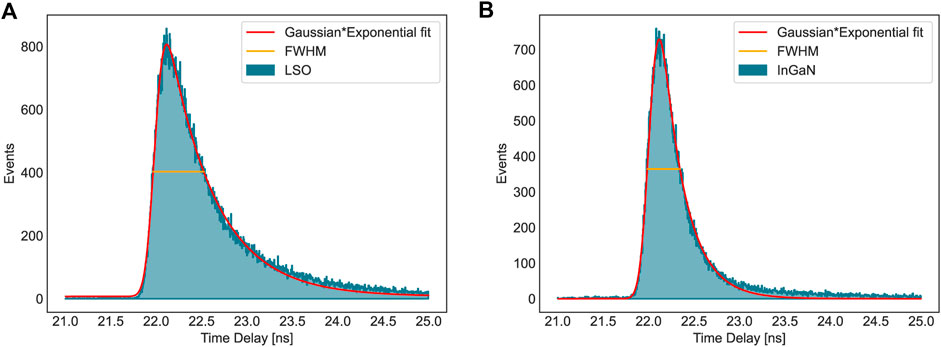
FIGURE 2. Time delay distribution of LSO (A) and InGaN (B) fitted with the convolution between Gaussian and exponential functions to extrapolate the FWHM.
Since the DTR was evaluated by taking into account all the events, we chose the mean collected charge (i.e., the mean of the charge distribution as shown in Figure 3) as a figure of merit for the light output to correlate it correctly with the time resolution.
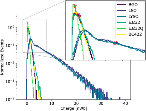
FIGURE 3. Integrated charge distribution of all the measured standard scintillators. The red outlined stars (filled with the colors of the corresponding distribution) represent the mean collected charge.
The IRF of the TCSPC setup Since the IRF of the TCSPC setup is about 160ps FWHM, for most of the measured samples, the rise time resulted as comparable to or below the accuracy of our system. Only for LSO and LYSO, the fit was performed by letting free all the parameters, and we measured a sub-30 ps component for both, plus a slower component of about 300 ps contributing to the 6% (LSO) and 23% (LYSO). For all the other standard scintillators, the rise time was fixed during the fit procedure, according to values obtained in a previous research work [14] (generally between 0 and 20 ps), to get more stability on the decay part of the pulse, of greater interest for this study. Also, the two nano-scintillators showed a non-resolvable rise time with the IRF of our system, and as it was found not to improve the quality of the fit, it was fixed to 0 ps.
The decay time components resulting from the bi-exponential fit of the scintillation time profiles are summarized in Table 2. In the last column, the effective decay time for each sample is also reported. It should be noticed that, in the weighted harmonic mean, more importance is given to the fastest component instead of the component with the highest abundance (as opposed to the standard weighted mean). This is intrinsic to its mathematical definition (Eq. 2), and it explains why, for instance, looking at BGO, the effective decay time is only 129 ± 10 ns though the main component (contributing to 92%) is 318 ± 22 ns. However, if we look at the single components, the results of our measurements are in agreement with those present in the literature [14,33].

TABLE 2. Summary table with decay time components resulting from the bi-exponential fit of scintillation pulses of all measured samples.
In Figure 4, the time delay distributions of all standard scintillators measured are shown. The DTR values are summarized in Table 3, together with the effective decay time and light output. A correlation between DTR and effective decay time can be observed: generally, the faster the decay time, the better the time resolution. However, this is not always the case, as the light output also needs to be taken into account.
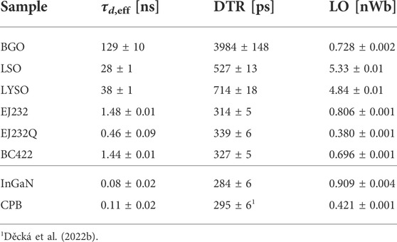
TABLE 3. Summary table with effective decay time (τd,eff), time resolution at FWHM (DTR), and light output (LO), defined as the mean of the collected charge distribution.
Vinogradov [34] thoroughly discussed how to analytically model the (coincidence) time resolution, and the proposed model has been experimentally verified by Gundacker et al. [14]. Though several parameters are involved in this model (which take into account not only the sample but also the photon time spread in the crystal, the photodetector, and the readout electronics), the main contribution to time resolution is given by the photon time density (PTD), defined as the ratio between light output and effective decay time:
This relation—already established—was verified in order to validate the new installed experimental setup and method to evaluate time resolution and light output upon X-ray excitation with SiPM. In Figure 5, the measured DTR is represented as a function of the square root of the measured photon time density. The data were fitted with the function
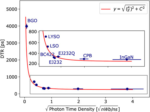
FIGURE 5. For all samples, the measured DTR is shown as a function of the square root of photon time density, defined as the ratio between the mean collected charge and the effective decay time. The data were fitted with the function
In Figure 6, the correlation between the deposited energy (i.e., integrated charge) and time resolution is shown for the LSO sample. From Figures 6B and C, one can observe that the greater the deposited energy, the narrower the time delay distribution. Specifically, the DTR and the square root of deposited energy are expected to be inversely proportional. To verify this relation, the charge distribution of LSO was divided into five intervals containing approximately the same amount of events (Figure 6B); for each of these intervals, the mean charge was evaluated, and the time delay distribution of the corresponding events was considered (Figure 6C). The DTR was evaluated as described in Section 2.3 for each distribution and studied as a function of the mean charge (Figure 6D). Finally, the data were fitted with the same function as before—
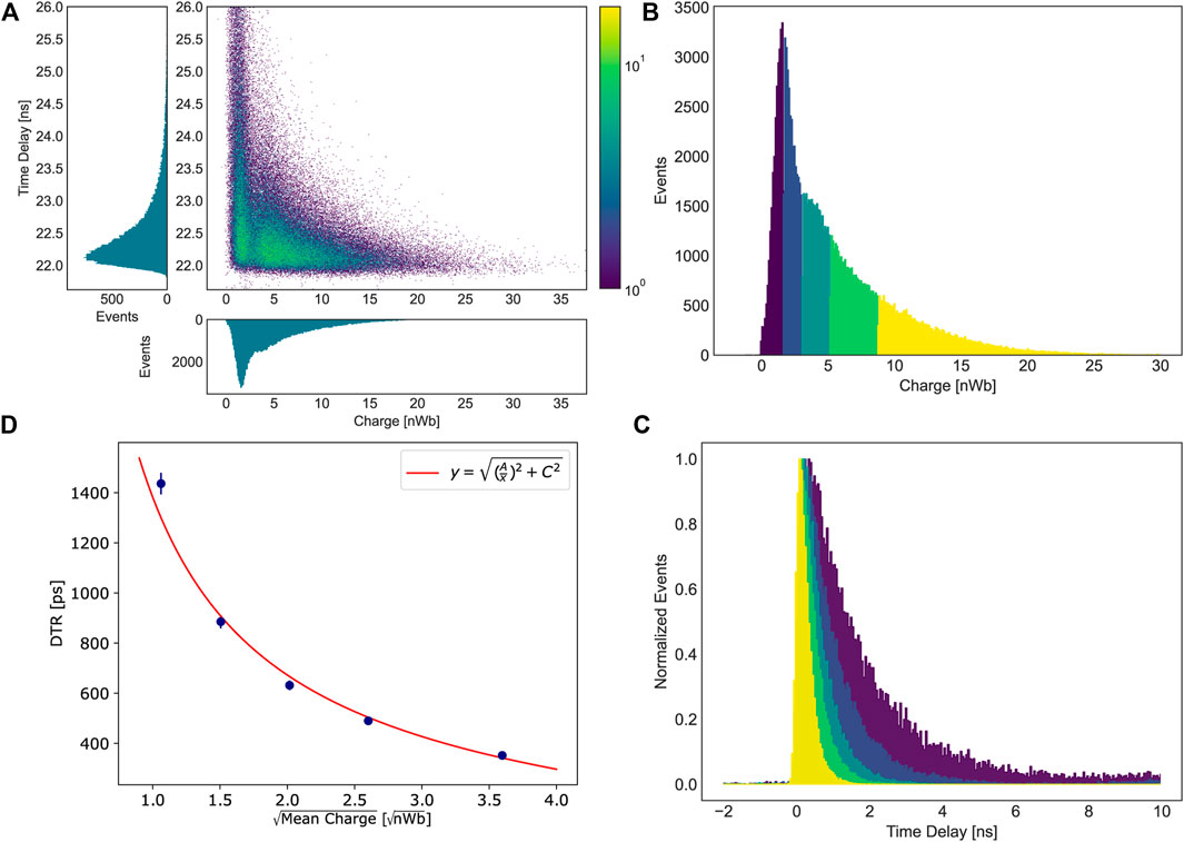
FIGURE 6. Correlation between time resolution (DTR) and deposited energy (mean integrated charge) for LSO. 2D histogram of time delay versus integrated charge (A). The charge distribution of LSO has been divided into five intervals containing about the same number of events (B); for each interval, the mean charge was evaluated, and the time delay distribution was considered (C). The DTR was evaluated as the FWHM of the distribution. Finally the DTR was plotted as function of the square root of the mean charge and fitted with
In Figure 7, the charge distribution of low stopping power samples (the two nanomaterials and EJ232 plastic scintillator) is compared to that of only SiPM + Meltmount. We can observe that even in the case of direct interaction of X-rays with Meltmount or SiPM, the resulting light output is negligible. Therefore, based on the previous discussion on the correlation between timing and collected charge, we can conclude that the contribution of SiPM and coupling medium to the measured DTR of our samples is negligible, ultimately confirming the effectiveness of this method with low stopping power samples.
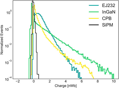
FIGURE 7. Comparison between the integrated charge of low stopping power samples (EJ232, InGaN, and CPB) and only SiPM.
Some of the measured samples showed ultra-fast decay kinetics. The exponential model used to fit the time profile gave a decay component in the order of 10 ps both for InGaN and CPB samples. Moreover, to properly fit the decay pulse of CPB, four decay components were needed. We are aware that these ultra-fast components, together with the need for many decay components, suggest that the exponential model might not be the best one to describe the physical processes generating the scintillation of these materials. A different model to better describe the decay profile of this kind of sample was recently proposed by Děcká et al. [28] on the trail of the one used by Gundacker et al. [30] to fit Cherenkov emission on top of scintillation. It consists in adding a Dirac-delta contribution to the exponential part to properly account for the (semi-)prompt emission. As already mentioned, Wang et al. [31] included a more detailed physical explanation of the non-exponential contribution in their model.
However, this study does not aim to give a physical interpretation of the single components but to find an adequate figure of merit to describe the impact of the decay kinetics on time resolution. Once the pulse is properly described by a sum of exponentials, the effective decay time offers that figure of merit. To ensure we are using the correct number of exponential components to model the scintillation time profile of nano-scintillators, we performed the fit with a number of decay components ranging between 2 and 5, and for each fit, we evaluated the reduced chi-squared
Furthermore, the multi-exponential fit of both InGaN MQW and CsPbBr3 nanocrystals has been reported in the literature [17,19].
We used the mean collected charge as the figure of merit for the light output. It is worth mentioning that other figures of merit can be equally valid, such as the peak at 9–10 keV if well-identifiable, or the end-point of the distribution, which, for standard scintillators, corresponds to the maximum energy of X-rays, i.e., 40 keV. However, these are not as versatile as the mean collected charge because the 9–10 keV peak cannot be identified for all samples (due to low stopping power for nanomaterials or too low photon time density AS for BGO–Figures 7 and 3, respectively) and because, for nanomaterials, it is not trivial to determine the maximum energy deposited and then convert in scintillating photons. Therefore, we chose the figure of merit which could better fit all the different samples object of this study.
So far, we stated light output as the mean collected charge without applying any correction factor (e.g., calibration for single photoelectron pulse (SPe), photodetection efficiency (PDE), light transfer efficiency (LTE), excess charge factor (ECF) coming from SiPM crosstalk, and non-proportionality (NP)) which would allow extrapolating the intrinsic light yield (number of emitted photons per keV). We did so because this method is more widely applicable, also without optimized readout electronics, allowing for relative light yield measurements with respect to a known crystal (e.g., L(Y)SO). However, the high gain of the amplifier and the high PDE of the used SiPM allow, in principle, for absolute measurements. To calibrate the SiPM, a dark count measurement—with the SiPM bias voltage equal to the one used for all other measurements—was performed. By integrating the energy signal, a finger plot was obtained (Figure 8), which allowed distinguishing pulses generated by one, two, three, etc., triggered SPADs. The distance between two adjacent peaks gives the charge corresponding to one triggered SPAD and, hence, the charge corresponding to single-photoelectron signals (SPe). To reduce the systematic error, we evaluated the distances between the first four adjacent fingers, and we used the arithmetic mean as the calibration factor, obtaining 0.05 ± 0.01 nWb.
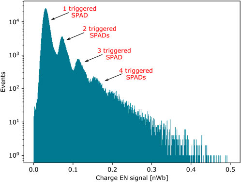
FIGURE 8. Finger plot of the energy (EN) channel obtained from a dark count measurement of S13360-3050CS Hamamatsu SiPM at 61 V bias voltage (53 V breakdown voltage).
Since, for LSO, both the deposited energy and all corrective factors are sufficiently well-known, we estimated its ILY starting from our light output measurements. The weighted PDE of a Hamamatsu S13360 SiPM for co-doped LSO emission is reported to be 0.59 ± 0.03 [14]. The light yield non-proportionality with the deposited energy depends on the exact doping of the crystal, and different values were found in the literature, ranging from 0.55 to 0.7 at 15 keV [35,36]: we opted for NP = 0.65 ± 0.1, and its high relative error was the main contribution to the final error. Following the method explained by Vinogradov [37] and Kratochwil et al. [38], the ECF at the operational bias voltage was measured to be 1.33 ± 0.07. Finally, by considering the LTE value of 0.66 reported by Gundacker et al. [14] for identical crystals (same size, doping, surface state, and producer) wrapped in Teflon, we performed relative light output measurements with and without Teflon wrapping, finding an LTE of 0.35 ± 0.02 for unwrapped co-doped LSO crystal. By taking into account all these corrective factors, we obtain
which is in good agreement with the value obtained by Gundacker et al. [14] of 39.2 ± 3.9 ph/keV, confirming the validity of the chosen figure of merit for the light output and of the calibration procedure.
With the same procedure, the intrinsic light yield of any samples measured with the described method can be obtained. However, a good knowledge of the corrective factors is needed and, in particular for nanomaterials, this may require complementary measurements.
This experimental setup allows measuring the time resolution upon pulsed X-ray irradiation. The importance of these measurements can be understood from Figure 5, where the relation between time resolution and photon time density is shown. Indeed, although fast scintillation kinetics is essential to have sub-100 ps time resolution, it is not the only requirement, and the other main parameter to consider is light output. Looking at Table 3, one can notice that although EJ232Q shows a sub-nanosecond effective decay time, approximately three times faster than that of EJ232 and BC422, it does not perform better than these two in terms of time resolution. This is explained by the—expected—lower light output of EJ232Q than that of the other two plastics.
Being able to measure time resolution at low energy, one inherently obtains information on light output, and simply by considering the relation between time resolution and deposited energy, one can estimate the time performance at higher energies. For instance, for LSO, a DTR of 527 ± 13 ps was measured at 15 keV mean deposited energy, and at 511 keV, we can expect a CTR of
Taking into account also the different LTE for 3 × 3 × 3 mm3 LSO crystal wrapped in Teflon and unwrapped—0.66 and 0.35, see Section 4.2—we obtain a correction factor of
It should be pointed out that when stating DTR values as FWHM of the time delay peak, we are assuming zero contribution from the system, which, of course, is not the case. Looking at Figure 5, to properly model the relation between DTR and photon time density, a constant term (the parameter C) was added in quadrature to the photon time density. From the analytical model [37], a perfect, ideal detector with infinite PTD should feature 0 ps DTR. It is, therefore, reasonable to assume that the parameter C—which from the fit resulted to be 247 ± 10 ps—is related to the system IRF. A rough estimation of the system contribution can be made from that of the TCSPC setup—160 ps (Section 2.2.1). The main difference in the detection chain of the two setups is the photodetector: in the TCSPC bench, the HPM has an IRF below 20 ps [39], while in the DTR and LO bench, the SPTR of Hamamatsu S13360 SiPM was measured to be 144 ps [14]. By approximating all the contributions to be Gaussian, the system IRF of the X-ray DTR setup result to be around 215 ps, compatible with the fit result within three sigma values. However, also in the choice of the fit function, all contributions were considered to be Gaussian, but this being a strong approximation, we decided not to correct the measured DTR values for system IRF. It is worth emphasizing that proper modeling of the system’s IRF contribution and its subtraction—or a better IRF—would allow for achieving even better intrinsic DTR values.
The possibility to measure time resolution at 10–15 keV and scale it to higher energy is of fundamental importance for those materials which cannot be directly characterized at the desired energy. Gundacker et al. [14] stated a CTR of 35 ± 2 ps (25 ± 1 ps DTR) at 340 keV for the BC422 plastic scintillator. Under X-ray irradiation, this scintillator showed a DTR of 327 ± 5 ps, while the two nanomaterials measured—InGaN and CPB—284 ± 6 ps and 295 ± 6 ps, respectively. Taking into account that the mean deposited energy in the two nanomaterials is most likely lower than in plastic, this suggests that if the stopping power could be increased, these materials would feature even better time resolution, which is explained by their higher photon time density (Figure 5).
Therefore, the presented experimental setup can play a key role in the characterization of these materials and guide their development as radiation detectors for fast timing applications, such as TOF-PET and in HEP [1,2,40].
Moreover, the direct applicability of this setup can be TOF X-ray imaging: the possibility to exploit TOF information to reduce the contribution from scattered photons was already presented by Pichette et al. [5] and Bérubé-Lauzière et al. [6] and first proof of concept of TOF CT by Rossignol et al. [7]. Further studies based on GATE simulations by Rossignol et al. [41] showed that already 200 ps time resolution can remove half of the scattered photons, significantly improving the image quality compared to non-TOF CT. Considering that an X-ray tube emitting photons with energy up to 40 keV and mean energy of about 15 keV were used in this study, at the typical energies of CT (20–150 keV), all the tested plastic scintillators would already exhibit better than 200 ps time resolution—at least in laboratory condition—and compatibly with the system IRF.
In this contribution, we present a new method to simultaneously measure the time resolution and light output of scintillators using pulsed X-ray irradiation and SiPM photodetectors. Because of the low irradiation energy (0–40 keV continuous spectrum, with mode energy 10 keV and mean energy 15 keV), the high photodetection efficiency (PDE) of SiPM, and the optimized electronics, this method is particularly suited for the characterization of materials with low stopping power (due to low density or microscopic size; InGaN/GaN MQW and CsPbBr3).
We based the validation of this method on the relation between time resolution and photon time density. First, we focused on standard scintillators (LSO:Ce:0.2%Ca, LYSO:Ce, BGO, BC422, EJ232, and EJ232Q), and then we tested two nanomaterial samples as a first proof-of-concept, finding the expected trend.
The strength of X-ray DTR measurements is to provide a better understanding of the potential of certain materials for fast timing applications at higher energy (e.g., TOF-PET and in HEP) compared to the standard rise and decay time measurement. The latter indeed takes into account only the scintillation kinetics of the sample, while time resolution measurements, being affected by the number of detected photons, intrinsically bring information also about its light output. Therefore, simply by scaling for the energy and applying proper corrections, the timing performances at higher energy than measurement conditions can be predicted.
Another positive implication of this setup is the possibility to characterize materials for fast X-ray detectors to be used for TOF CT or, more in general, TOF X-ray imaging.
The raw data supporting the conclusion of this article will be made available by the authors, without undue reservation.
MS and SG contributed to the conception of the study, and FP and NK contributed to its design. The experimental measurements and the data analysis were carried out by FP, and the whole work was supervised by NK, MS, and EA. FP wrote the manuscript, which was accurately reviewed by all the authors who approved the submitted version.
This work was carried out in the frame of the Crystal Clear Collaboration and the CERN quantum initiative. It was supported by the CERN Budget for Knowledge Transfer to Medical Applications, and it also received funding in the framework of AIDA Innova.
The authors acknowledge Alice Hospodková, with the whole team from FZU, Institute of Physics of the Czech Academy of Sciences in Prague, and Kateřina Děcká, with the whole team from CTU, Czech Technical University in Prague, for providing us with InGaN/GaN and CsPbBr3 samples, respectively.
The authors declare that the research was conducted in the absence of any commercial or financial relationships that could be construed as a potential conflict of interest.
All claims expressed in this article are solely those of the authors and do not necessarily represent those of their affiliated organizations, or those of the publisher, the editors, and the reviewers. Any product that may be evaluated in this article, or claim that may be made by its manufacturer, is not guaranteed or endorsed by the publisher.
1. Moses WW, Derenzo S. Prospects for time-of-flight pet using lso scintillator. IEEE Trans Nucl Sci (1999) 46:474–8. doi:10.1109/23.775565
2. Conti M. Focus on time-of-flight pet: The benefits of improved time resolution. Eur J Nucl Med Mol Imaging (2011) 38:1147–57. doi:10.1007/s00259-010-1711-y
3. Perali I, Celani A, Bombelli L, Fiorini C, Camera F, Clementel E, et al. Prompt gamma imaging of proton pencil beams at clinical dose rate. Phys Med Biol (2014) 59:5849–71. doi:10.1088/0031-9155/59/19/5849
4. Lopes PC, Clementel E, Crespo P, Henrotin S, Huizenga J, Janssens G, et al. Time-resolved imaging of prompt-gamma rays for proton range verification using a knife-edge slit camera based on digital photon counters. Phys Med Biol (2015) 60:6063–85. doi:10.1088/0031-9155/60/15/6063
5. Pichette J, Domínguez JB, Bérubé-Lauzière Y. Time-domain geometrical localization of point-like fluorescence inclusions in turbid media with early photon arrival times. Appl Opt (2013) 52:5985–99. doi:10.1364/ao.52.005985
6. Bérubé-Lauzière Y, Crotti M, Boucher S, Ettehadi S, Pichette J, Rech I. Prospects on time-domain diffuse optical tomography based on time-correlated single photon counting for small animal imaging. J Spectrosc (2016) 2016:1–23. doi:10.1155/2016/1947613
7. Rossignol J, Turtos RM, Gundacker S, Gaudreault D, Auffray E, Lecoq P, et al. Time-of-flight computed tomography-proof of principle. Phys Med Biol (2020) 65:085013. doi:10.1088/1361-6560/ab78bf
8. Lucchini MT, Chung W, Eno SC, Lai Y, Lucchini L, Nguyen M, et al. New perspectives on segmented crystal calorimeters for future colliders. J Instrum (2020) 15:P11005. doi:10.1088/1748-0221/15/11/p11005
9. Benaglia A, Gundacker S, Lecoq P, Lucchini M, Para A, Pauwels K, et al. Detection of high energy muons with sub-20 ps timing resolution using l (y) so crystals and sipm readout. Nucl Instr Methods Phys Res Section A: Acc Spectrometers, Detectors Associated Equipment (2016) 830:30–5. doi:10.1016/j.nima.2016.05.030
10. Cms Collaboration C. A mip timing detector for the cms phase-2 upgrade. Colorado: CERN, Geneva, Tech (2019).
11. Gundacker S, Auffray E, Frisch B, Jarron P, Knapitsch A, Meyer T, et al. Time of flight positron emission tomography towards 100ps resolution with l (y) so: An experimental and theoretical analysis. J Instrum (2013) 8:P07014. doi:10.1088/1748-0221/8/07/p07014
12. Cates JW, Gundacker S, Auffray E, Lecoq P, Levin CS. Improved single photon time resolution for analog sipms with front end readout that reduces influence of electronic noise. Phys Med Biol (2018) 63:185022. doi:10.1088/1361-6560/aadbcd
13. Gundacker S, Turtos RM, Auffray E, Paganoni M, Lecoq P. High-frequency sipm readout advances measured coincidence time resolution limits in tof-pet. Phys Med Biol (2019) 64:055012. doi:10.1088/1361-6560/aafd52
14. Gundacker S, Turtos RM, Kratochwil N, Pots RH, Paganoni M, Lecoq P, et al. Experimental time resolution limits of modern sipms and tof-pet detectors exploring different scintillators and cherenkov emission. Phys Med Biol (2020) 65:025001. doi:10.1088/1361-6560/ab63b4
15. Pourashraf S, Gonzalez-Montoro A, Won JY, Lee MS, Cates JW, Zhao Z, et al. Scalable electronic readout design for a 100 ps coincidence time resolution tof-pet system. Phys Med Biol (2021) 66:085005. doi:10.1088/1361-6560/abf1bc
16. Cates JW, Steele J, Balajthy J, Negut V, Hausladen P, Ziock K, et al. Front-end design for sipm-based monolithic neutron double scatter imagers. Sensors (2022) 22:3553. doi:10.3390/s22093553
17. Hospodková A, Nikl M, Pacherová O, Oswald J, Brůža P, Pánek D, et al. InGaN/GaN multiple quantum well for fast scintillation application: Radioluminescence and photoluminescence study. Nanotechnology (2014) 25:455501. doi:10.1088/0957-4484/25/45/455501
18. Perego J, Villa I, Pedrini A, Padovani E, Crapanzano R, Vedda A, et al. Composite fast scintillators based on high-z fluorescent metal–organic framework nanocrystals. Nat Photon (2021) 15:393–400. doi:10.1038/s41566-021-00769-z
19. Děcká K, Král J, Hájek F, Průša P, Babin V, Mihóková E, et al. Scintillation response enhancement in nanocrystalline lead halide perovskite thin films on scintillating wafers. Nanomaterials (2022) 12:14. doi:10.3390/nano12010014
20. Liu F, Wu R, Wei J, Nie W, Mohite AD, Brovelli S, et al. Recent progress in halide perovskite radiation detectors for gamma-ray spectroscopy. ACS Energ Lett (2022) 7:1066–85. doi:10.1021/acsenergylett.2c00031
21. Turtos RM, Gundacker S, Auffray E, Lecoq P. Towards a metamaterial approach for fast timing in pet: Experimental proof-of-concept. Phys Med Biol (2019) 64:185018. doi:10.1088/1361-6560/ab18b3
22. Turtos R, Gundacker S, Omelkov S, Mahler B, Khan A, Saaring J, et al. On the use of cdse scintillating nanoplatelets as time taggers for high-energy gamma detection. Npj 2d Mater Appl (2019) 3:37–10. doi:10.1038/s41699-019-0120-8
23. Lecoq P, Konstantinou G, Latella R, Moliner L, Nuyts J, Zhang L, et al. Metascintillators: New results for tof-pet applications. IEEE Trans Radiat Plasma Med Sci (2022) 6:510–6. doi:10.1109/trpms.2022.3161473
24. Pagano F, Kratochwil N, Salomoni M, Pizzichemi M, Paganoni M, Auffray E. Advances in heterostructured scintillators: Toward a new generation of detectors for tof-pet. Phys Med Biol (2022) 67:135010. doi:10.1088/1361-6560/ac72ee
25. Turtos R, Gundacker S, Omelkov S, Auffray E, Lecoq P. Light yield of scintillating nanocrystals under x-ray and electron excitation. J Lumin (2019) 215:116613. doi:10.1016/j.jlumin.2019.116613
28. Děcká K, Pagano F, Frank I, Kratochwil N, Mihóková E, Čuba V, et al. (2022). Timing performance of lead halide perovskite nanoscintillators embedded in polystyrene matrix. accepted in J Mater Chem C
29. Bollinger L, Thomas GE. Measurement of the time dependence of scintillation intensity by a delayed-coincidence method. Rev Scientific Instr (1961) 32:1044–50. doi:10.1063/1.1717610
30. Gundacker S, Turtos R, Auffray E, Lecoq P. Precise rise and decay time measurements of inorganic scintillators by means of x-ray and 511 kev excitation. Nucl Instr Methods Phys Res Section A: Acc Spectrometers, Detectors Associated Equipment (2018) 891:42–52. doi:10.1016/j.nima.2018.02.074
31. Wang Y, Xu S, Zhao D, Zhu J, Yang H, Shan X, et al. Non-exponential photoluminescence decay dynamics of localized carriers in disordered ingan/gan quantum wells: The role of localization length. Opt Express (2006) 14:13151–7. doi:10.1364/oe.14.013151
32. Kratochwil N, Gundacker S, Lecoq P, Auffray E. Pushing Cherenkov PET with BGO via coincidence time resolution classification and correction. Phys Med Biol (2020) 65:115004. doi:10.1088/1361-6560/ab87f9
33. Cala R, Kratochwil N, Martinazzoli L, Lucchini M, Gundacker S, Galenin E, et al. Characterization of mixed Bi4(GexSi1−x)3O12 for crystal calorimetry at future colliders. Nucl Instr Methods Phys Res Section A: Acc Spectrometers, Detectors Associated Equipment (2022) 1032:166527. doi:10.1016/j.nima.2022.166527
34. Vinogradov S. Approximations of coincidence time resolution models of scintillator detectors with leading edge discriminator. Nucl Instr Methods Phys Res Section A: Acc Spectrometers, Detectors Associated Equipment (2018) 912:149–53. doi:10.1016/j.nima.2017.11.009
35. Moses W, Bizarri G, Williams RT, Payne S, Vasil’Ev A, Singh J, et al. The origins of scintillator non-proportionality. IEEE Trans Nucl Sci (2012) 59:2038–44. doi:10.1109/tns.2012.2186463
36. Wanarak C, Chewpraditkul W, Phunpueok A. Light yield non-proportionality and energy resolution of lu1. 95y0. 05sio5: Ce and lu2sio5: Ce scintillation crystals. Proced Eng (2012) 32:765–71. doi:10.1016/j.proeng.2012.02.010
37. Vinogradov S. Analytical models of probability distribution and excess noise factor of solid state photomultiplier signals with crosstalk. Nucl Instr Methods Phys Res Section A: Acc Spectrometers, Detectors Associated Equipment (2012) 695:247–51. doi:10.1016/j.nima.2011.11.086
38. Kratochwil N, Gundacker S, Auffray E. A roadmap for sole cherenkov radiators with sipms in tof-pet. Phys Med Biol (2021) 66:195001. doi:10.1088/1361-6560/ac212a
39. Lucchini M. Combining dual-readout crystals and fibers in a hybrid calorimeter for the idea experiment. EPS-HEP (2021).
40. Rossignol J, Marcoux P, Bélanger G, Gagnon F, Dufour P, Corbeil Therrien A, et al. Toward a first prototype time-of-flight ct scanner. Valencia, Spain: Workshop on fast time for medical imaging (2022).
Keywords: timing detectors, time-of-flight, x-ray detectors, scintillators, nanomaterials
Citation: Pagano F, Kratochwil N, Frank I, Gundacker S, Paganoni M, Pizzichemi M, Salomoni M and Auffray E (2022) A new method to characterize low stopping power and ultra-fast scintillators using pulsed X-rays. Front. Phys. 10:1021787. doi: 10.3389/fphy.2022.1021787
Received: 17 August 2022; Accepted: 10 October 2022;
Published: 28 October 2022.
Edited by:
Arianna Morozzi, Istituto Nazionale di Fisica Nucleare di Perugia, ItalyReviewed by:
Christos Michail, University of West Attica, GreeceCopyright © 2022 Pagano, Kratochwil, Frank, Gundacker, Paganoni, Pizzichemi, Salomoni and Auffray. This is an open-access article distributed under the terms of the Creative Commons Attribution License (CC BY). The use, distribution or reproduction in other forums is permitted, provided the original author(s) and the copyright owner(s) are credited and that the original publication in this journal is cited, in accordance with accepted academic practice. No use, distribution or reproduction is permitted which does not comply with these terms.
*Correspondence: Fiammetta Pagano, ZmlhbW1ldHRhLnBhZ2Fub0BjZXJuLmNo
†Present address: Stefan Gundacker, Department of Physics of Molecular Imaging Systems, Institute for Experimental Molecular Imaging, RWTH Aachen University, Aachen, Germany
Disclaimer: All claims expressed in this article are solely those of the authors and do not necessarily represent those of their affiliated organizations, or those of the publisher, the editors and the reviewers. Any product that may be evaluated in this article or claim that may be made by its manufacturer is not guaranteed or endorsed by the publisher.
Research integrity at Frontiers

Learn more about the work of our research integrity team to safeguard the quality of each article we publish.