- 1Department of Mathematics, University of Hafr Al Batin, Hafr Al Batin, Saudi Arabia
- 2Department of Mathematics, Air University, Islamabad, Pakistan
- 3Institute of Mathematics, Khwaja Fareed University of Engineering and Information Technology, Rahim Yar Khan, Pakistan
- 4International Cultural Exchange School, Donghua University, Shanghai, China
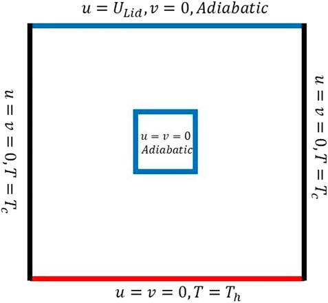
The current manifestation is utilized to explicate the inspiration of combined convection flows in a cavity with a square cylinder placed at the center of the cavity having coordinates (0.5, 0.5). To be more specific, right- and left-sided vertical walls are kept cold, and the lower wall is to be heated in uniform and non-uniform manners, while the upper horizontal wall is moved with a constant velocity
Introduction
An energy transfer situation that arises due to forced and natural convection is considered mixed convection. It is the type of convection in which natural convection and forced convection are comparable. Thus, mixed convection arises due to the impact of forces generated, density differences on forced flow, or the outcome of forced flow on the buoyant flow. In recent years, thermally driven flows have generated prodigious interest from researchers, especially in confined enclosures due to their pervasive applications in engineering and industrial procedures. Based on the complicated and highly beneficial coupling of forced and free convection, various authors have presented many research studies in this regard. Lyican et al. [1] reconnoitered the free convective motion and thermophysical aspects in a trapezoidal enclosure with adiabatically heated side walls by the implementation of Galerkin’s method. Roy and Basak [2] presented a numerical scheme for natural convection flows with non-uniformly heated walls within a cavity. The influence of sinusoidal wavy base surface on dual convection in the compelled cavity is considered by Amiri et al. [3]. Varol et al. [4, 5] executed a speculative analysis of heat transferal in a bent trapezoidal-structured field occupied with a fluid-saturated porosity medium along with cold and heated walls. Basak et al. [6] implemented a highly potential finite element quadratically based paired scheme to scrutinize the parametric aspects of convective flow in the square-shaped confined enclosure with a non-uniform heated wall. In order to investigate the different heat flow patterns that various trapezoidal cavities exhibit, Basak et al. [7] presented the results of a comprehensive analysis of heat lines. The rate of convection in a cavity with a volumetric heat source and wavy walls was investigated by Oztop et al. [8]. In this study, the vertical walls were assumed to be undulating and to be at a range of temperatures, whereas the assumption was made that the upper and lower horizontal walls were adiabatic. Mahmoodi and Pour [9] engrossed that the flow features imparted by transferring heat within cavity enclosure replete with a fluid and non-magnetic convective fluid flow is investigated numerically have presented heat transfer because of the cavity natural convection with cold side walls and the lower wall being warmth in the existence of top wall insulated. Rehman et al. [10] executed a computational study to perform depiction using fluid flow in a porosity medium and natural convection heat transfer.
A numerical investigation is conducted for the ferrofluid flow inside a cavity under mixed convection by setting different configurations of heaters by Rabbia et al. [11]. Hayat et al. [12] explored the thermal radiation effect in the presence of Joule heating by considering fluid flow over Eyring–Powell over a stretching sheet. They also incorporated the effects of Soret and Dufour in the simulations and produced results for velocity profiles and other relevant parameters. The MHD flow of Burgers fluid is considered in another study by Hayat et al. [13] with additional effects introduced by Joule heating. In this study, the authors found a series of solutions, and the results discussed in great detail the involved physical parameters. Anum et al. [14] simulated the von Karman flow of a nanofluid with temperature-dependent viscosity with the aid of a bvp4c solver and implicit finite difference schemes. The results therein were presented through graphs of concentration, temperature, and velocity profiles with various combinations of the dimensionless parameters. Salahuddin et al. [15] computed second-grade fluid profiles of flow by considering two models of temperature-dependent viscosity through suitable transformations converting the governing PDE system to an ODE system and thus solved by a bvp4c solver. The location’s influence on the heated triangular block within the cavity is investigated for mixed convection flow in a recent study by Gangawane et al. [16]. They performed simulations using the simple algorithm and finite volume method (FVM). They concluded that the maximum transfer rate of heat could be obtained for the central position of the block in the cavity. Extensive literature is available on applications of body-inserted cavities, see, for example, [17–19].
This research is predicated on the analysis of the properties of the MHD thermal flow in a cavity containing an insulated block. The Galerkin finite element scheme has been used for the simulation. The effects of the Hartmann number, the Reynolds number, and the inclination angle on thermal flow are taken into consideration.
Mathematical modeling
A steady, incompressible, laminar, and viscous fluid flow in a 2D square cavity is considered. The computational domain along with the boundary data is depicted in Figure 1. The cavity upper wall is permissible to shift at a uniform speed and is adiabatic thermally. The cavity’s left vertical and bottom walls are kept irregularly by fluctuating thermal distribution. The widely accepted Boussinesq approximation is employed in this article to cater to the reliance on density variation with respect to temperature. The density variations are small to moderate with temperature, so the approximation is fair enough to simulate the results. From the aforementioned discussion, equation (2) is expressed as follows:
subject to the velocity boundary conditions
The thermal boundary conditions for a uniform case are as follows:
For non-uniform cases, the boundary conditions for the temperature are as follows:
At the outer surface of the obstacle
where
By employing the subsequent transformation,
Equations 1-8 reduce to the non-dimensional form, given as
The velocity boundary conditions are given by
Also, thermal boundary conditions for the uniform case are given by
Also, for the non-uniform case, thermal boundary conditions are given by
For the cylindrical blockage,
where symbols have their usual meanings.
Numerical scheme and solvers
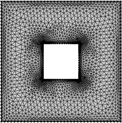
Fluid flow behavior in non-confined boundaries is easily handled using the way of exact approaches, but extracting the solution in a closed enclosure along with various shapes of an obstacle is difficult with the help of traditional methods. So, most of the researchers utilize numerical schemes to report the findings, and the most generous methods are FDM, FEM, and FVM. Among these aforementioned numerical methodologies, the finite element scheme [20–28] is a versatile method because the modeling of complex and irregular shapes is easily handled by discretizing the available domain with finite elements. For the computations of velocity and temperature, we made use of the stable quadratic elements, while the pressure was approximated using the linear elements. This particular design makes use of a hybrid finite element mesh that is composed of both rectangular and triangular elements. The computational mesh at the coarse grid level is disclosed in Figure 2, and the corresponding degrees of freedom at further refinement levels are shown in Table 1. Newton’s technique is used to adjust the non-linear equations, and the resulting linear system of equations is resolved through a direct solver based on elimination with special rearrangement of unknowns. The following convergence criterion is set for the nonlinear iterations:
where
Results and discussion
This segment highlights the outcomes of numerical computations of heat and flow transfer using the way of mixed convection in a square cavity field with a square obstacle whose length is 0.3. The experimental outcomes are produced for multiple values of the principal parameters. We would like to mention that the parametric study is restricted only to those values as selected in [6]. The lower wall is heated in both uniform and non-uniform manners, while the right wall is cold and the upper horizontal wall is insulated as a square cavity with a cold and uniformly heated square obstacle.
After acquiring the temperature and velocity fields, the important quantity of interest, namely, the average Nusselt number, and the local Nusselt number could be computed as post-processing using
In general,
The grid independency test and code validation
To make sure the convergence of numerical simulation to accurate results, the grid size is increased, and the effects shown are not dependent on the grid size. The code validation is shown in Table 2 for combined convection flow in the absence of an obstacle. The experimental results of this study are quite comparable with those presented in [29, 30]. In addition, code validation is also given in Table 3 for specific situations of cavity’s isothermal blockage, and these results are identical to [31].
Further parametric study and graphical outcomes
Figures 3, 4 display the streamlines and isotherms for the uniform heating of the lower wall for fixed values of Pr and Re but for changing the values of Gr number. The forced convection dominates the natural convection at
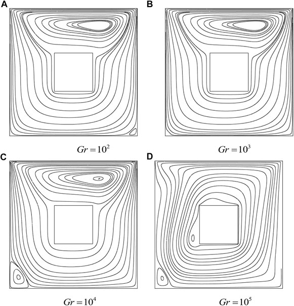
FIGURE 3. Influence of Gr on streamlines with a uniform heated bottom wall: cold cylinder case,
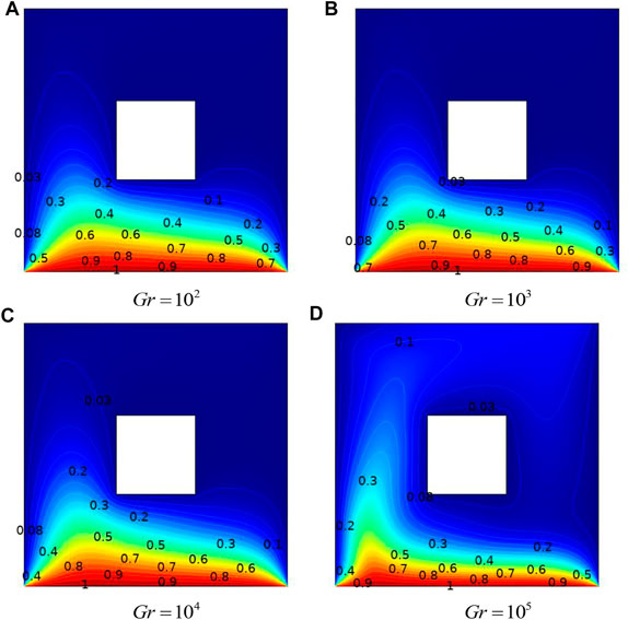
FIGURE 4. Influence of Gr on isotherms with a uniformly heated bottom wall: cold cylinder case,
Figure 4 exhibits the isotherms in the presence of a cold cylinder in the center. Due to this blockage, more isotherms are concentrated in the lower part of the cavity.
By increasing the values of Re, the effect of forced convection increases as depicted in Figure 5. One can notice that the strength of clockwise rotation increases with an increase in Re as expected due to dominancy over natural convection. Furthermore, the right secondary vortex disappears at higher Reynolds numbers.
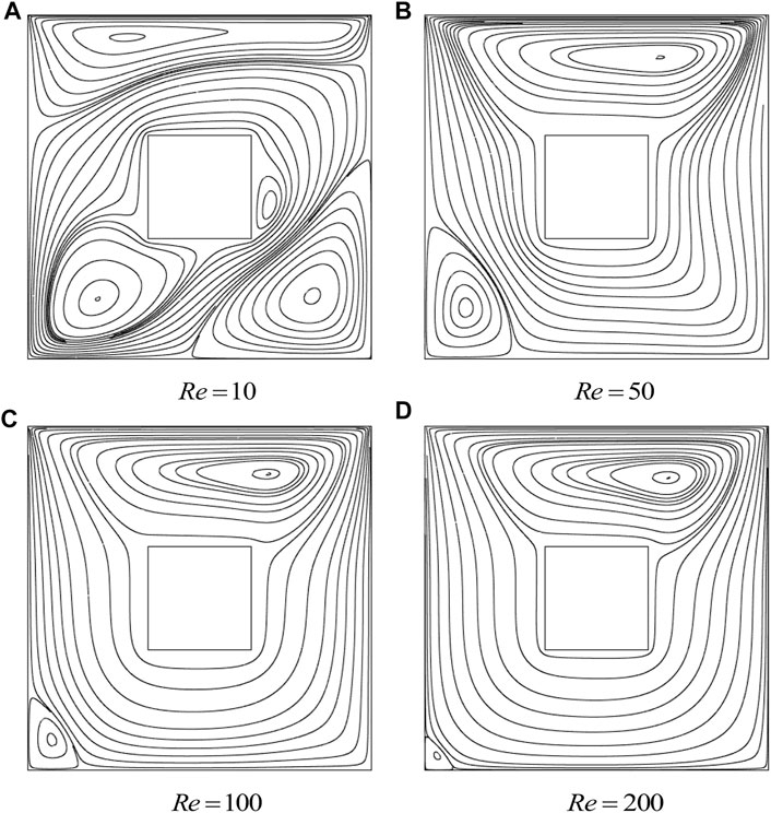
FIGURE 5. Influence of Re on streamlines with a uniformly heated bottom wall: cold cylinder case,
The effect of Re and Ha on isotherms at a constant value of
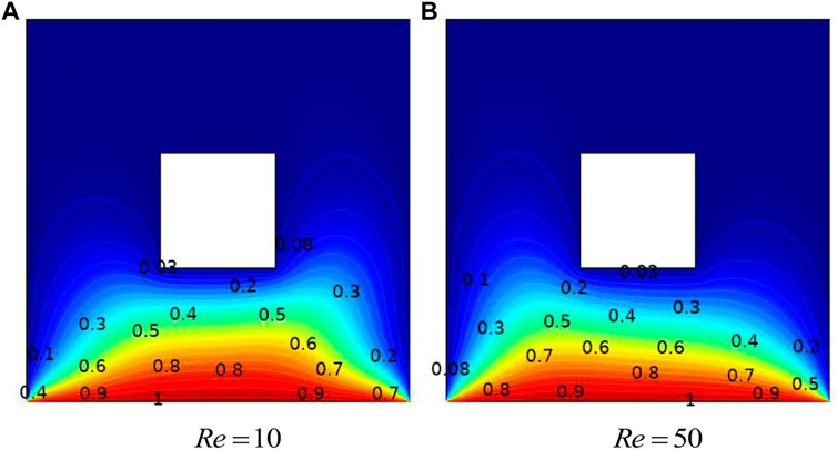
FIGURE 6. Influence of Re on isotherms with a uniformly heated bottom wall: cold cylinder case,
Variation in streamlines against different magnitudes of Ha, Gr and Re is explicated in Figures 7–13. Since
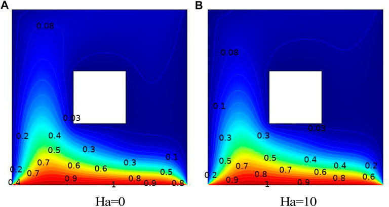
FIGURE 7. Influence of Ha on isotherms with a uniformly heated bottom wall: cold cylinder case,
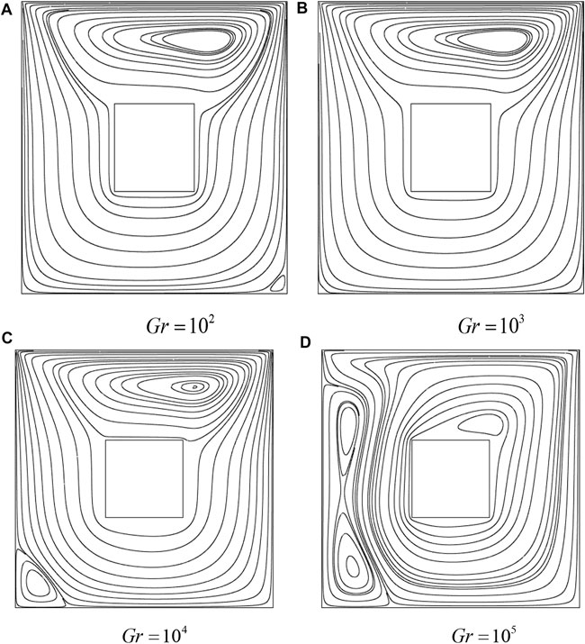
FIGURE 9. Influence of Gr on streamlines with a non-uniformly heated bottom wall: adiabatic cylinder with
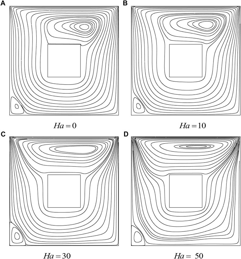
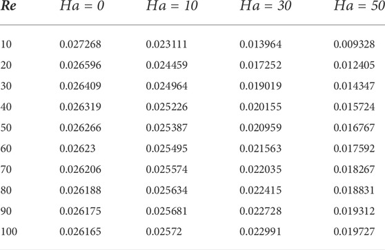
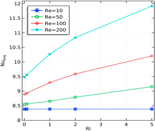
The impact of Gr, Re and Ha from lower values to higher values on isotherms for adiabatic cylinders through non-uniform heating is shown in Figures 10–14. For lower values of Ha, the isotherms are symmetrical regarding the center vertical lines; however, as we increase the value of Ha, the isotherms have been moved to the cavity left wall. In addition, we computed a global quantity that serves as a benchmark for driven cavity flows. Table 4 lists the computation of kinetic energy for an adiabatic square block configuration against Re versus Ha at Re = 10, Gr = 103. For an increase in Re magnitude, a decreasing trend in kinetic energy is observed at Ha = 0, and the same behavior is appeared for fixed Re and increase in Ha. This pattern results from higher Re, creating vortices, which divide the flow into various circulation types. The information about the change in the average Nusselt number against rising (Re) and (Ri) for uneven base wall heating is shown in Figure 15. Here, it is demonstrated that no appreciable change in the Nusselt number is observed for low magnitudes of (Re) and (Ri). However, a significant increase in the average Nusselt number is revealed for higher values of (Ri). The reason for this is that as (Ri) rises, the impact of buoyancy forces increases, causing the motion of fluid particles to accelerate and the transfer of heat from the heated wall to other areas of the enclosure to increase.
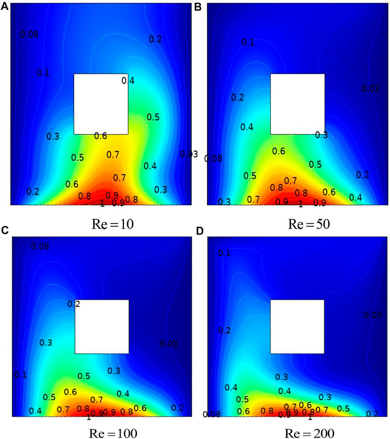
FIGURE 10. Influence of Re on streamlines with a non-uniformly heated bottom wall: adiabatic cylinder with
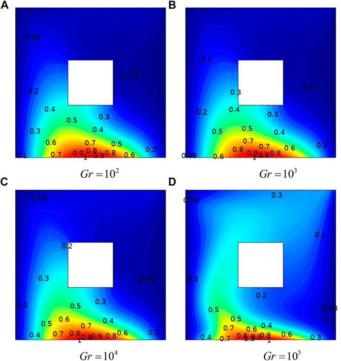
FIGURE 11. Influence of Ha on streamlines with a non-uniformly heated bottom wall: adiabatic cylinder with
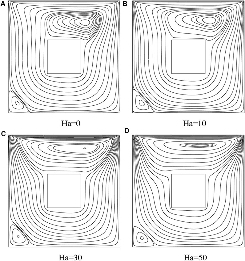
FIGURE 12. Influence of Gr on isotherms with a non-uniformly heated bottom wall: adiabatic cylinder with
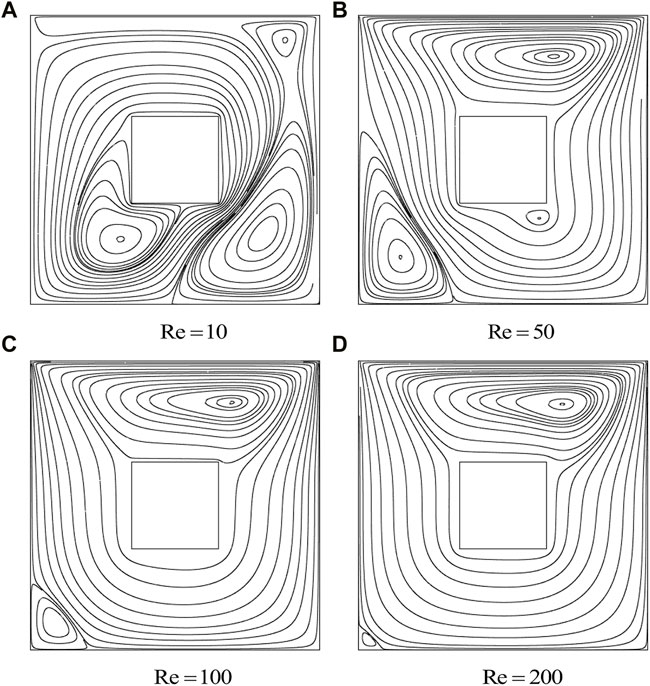
FIGURE 13. Influence of Re on isotherms with a non-uniformly heated bottom wall: adiabatic cylinder with
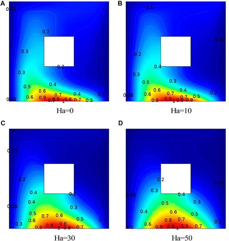
FIGURE 14. Influence of Ha on isotherms with a non-uniformly heated bottom wall: adiabatic cylinder with
Conclusion
The current work is addressed to investigate and interpret the thermophysical aspects of fluid flow enclosed in a square cavity in the presence of a blockage at the center. To expose the thermal features in the cavity, uniformly and non-uniformly heated walls are considered. Numerical computation is disclosed with the aid of finite element techniques by considering conforming element pairs
❖ The singularity in the thermal plot caused by uniform heating can be avoided by using a non-uniformly heating source.
❖ With an increase in Re and Ha, the kinetic energy of fluid molecules in the domain falls.
❖ The development of temperature disparities is associated with a significant increase in
❖ Present findings are in good agreement with those of Islam et al. [31] at all Ri numbers.
❖ The center of the primary vortex shifts, and it changes from circular to oval shape.
Data availability statement
The original contributions presented in the study are included in the article/Supplementary Material, further inquiries can be directed to the corresponding authors.
Author contributions
YK: funding; AM: computed the results; SA and NF: wrote the original draft; RM: supervision; AM: wrote the review draft; SA: modeling; RM: conceptualization; and YK, A.A, and NF: validation.
Funding
This research work was funded by the Institutional Fund Projects under no. (IFP-A- 2022-2-5-24).
Acknowledgments
The authors gratefully acknowledge technical and financial support from the Ministry of Education and the University of Hafr Al Batin, Saudi Arabia.
Conflict of interest
The authors declare that the research was conducted in the absence of any commercial or financial relationships that could be construed as a potential conflict of interest.
Publisher’s note
All claims expressed in this article are solely those of the authors and do not necessarily represent those of their affiliated organizations, or those of the publisher, the editors, and the reviewers. Any product that may be evaluated in this article, or claim that may be made by its manufacturer, is not guaranteed or endorsed by the publisher.
References
1. Lyican L, Bayazitoglu Y. An analytical study of natural convective heat transfer within trapezoidal enclosure. ASME Trans J Heat Transfer (1980) 102:640–7. doi:10.1115/1.3244365
2. Roy S, Basak T. Finite element analysis of natural convection flows in a square cavity with non- uniformly heated wall(s). Int J Eng Sci (2005) 45:668–80. doi:10.1016/j.ijengsci.2005.01.002
3. Al-Amiri AM, Khanafer KM, Pop I. Effect of sinusoidal wavy bottom surface on mixed convection heat transfer in a lid driven cavity. Int J Heat Mass Transf (2007) 50:1771–80. doi:10.1016/j.ijheatmasstransfer.2006.10.008
4. Varol Y, Oztop HF, Pop I. Numerical analysis of natural convection in an inclined trapezoidal enclosure filled with a porous medium. Int J Therm Sci (2008) 47(10):1316–31. doi:10.1016/j.ijthermalsci.2007.10.018
5. Varol Y, Oztop HF, Pop I. Natural convection in right-angle porous trapezoidal enclosure partially cooled from inclined wall. Int Commun Heat Mass Transfer (2009) 36(1):6–15. doi:10.1016/j.icheatmasstransfer.2008.09.010
6. Basak T, Roy S, Sharma P, Pop I. Analysis of mixed convection flows within a square cavity with uniform and non-uniform heating of bottom wall. Int J Therm Sci (2009) 48:891–912. doi:10.1016/j.ijthermalsci.2008.08.003
7. Basak T, Roy S, Pop I. Heat flow analysis for natural convection within trapezoidal enclosures based on heat line concept. Int J Heat Mass Transf (2009) 52:2471–83. doi:10.1016/j.ijheatmasstransfer.2009.01.020
8. Oztop HF, Abu-Nada E, Varol Y, Chamkha A. Natural convection in wavy enclosures with volumetric heat sources. Int J Therm Sci (2011) 50:502–14. doi:10.1016/j.ijthermalsci.2010.10.015
9. Mahmoodi M, Talea’pour Z. Magnetohydrodynamic free convection heat transfer in a square enclosure heated from side and cooled from the ceiling. Comput Therm Scien (2011) 3:219–26. doi:10.1615/computthermalscien.2011002689
10. Rahman MM, Oztop HF, Saidur R, mekhilef S, Al K. Unsteady mixed convection in a porous media filled lid-driven cavity heated by a semi-circular heaters. Therm Sci (2014) 19(5):1761–8. doi:10.2298/tsci130725098r
11. Rabbia KM, Sahaa S, Mojumdera S, Rahmanb MM, Saidurc R, Ibrahim TA. Numerical investigation of pure mixed convection in a ferrofluid-filled lid-driven cavity for different heater configurations. Alexandria Eng J (2016) 55(1):127–39. doi:10.1016/j.aej.2015.12.021
12. Hayat T, Ali S, Alsaedi A, Alsulami H. Influence of thermal radiation and Joule heating in the Eyring-Powell fluid flow with the Soret and Dufour effects. J Appl Mech Tech Phy (2016) 57(6):1051–60. doi:10.1134/s0021894416060122
13. Hayat T, Ali S, Awais M, Alsaedi A. Joule heating effects in MHD flow of Burgers fluid. Heat Transf Res (2016) 47(12):1083–92. doi:10.1615/heattransres.2016008093
14. Tanveer A, Salahuddin T, Khan M, Alshomrani AS, Malik MY. The assessment of nanofluid in a Von Karman flow with temperature relied viscosity. Results Phys (2018) 9:916–22. doi:10.1016/j.rinp.2018.03.051
15. Salahuddin T, Arif A, Haider A, Malik MY. Variable fluid properties of a second grade fluid using two different temperature dependent viscosity models. J Braz Soc Mech Sci Eng (2018) 40:575. doi:10.1007/s40430-018-1483-z
16. Gangawane KM, Oztop HF, Hamdeh NA. Mixed convection characteristic in a lid-driven cavity containing heated triangular block: Effect of location and size of block. Int J Heat Mass Transfer (2018) 124:860–75. doi:10.1016/j.ijheatmasstransfer.2018.03.079
17. Rashidi MM, Mahariq I, Nazari MA, Accouche O, Bhatti MM. Comprehensive review on exergy analysis of shell and tube heat exchangers. J Therm Anal Calorim (2022) 2022:1–11. doi:10.1007/s10973-022-11478-2
18. Pozrikidis C. Introduction to theoretical and computational fluid dynamics. Oxford, United Kingdom: Oxford University Press (1998).
19. Batchelor GK. An introduction to fluid dynamics. Cambridge, United Kingdom: Cambridge University Press (1993).
20. Majeed AH, Bilal S, Mahmood R, Malik MY. Heat transfer analysis of viscous fluid flow between two coaxially rotated disks embedded in permeable media by capitalizing non-Fourier heat flux model. Physica A: Stat Mech its Appl (2020) 540:123182. doi:10.1016/j.physa.2019.123182
21. Bilal S, Majeed AH, Mahmood R, Khan I, Seikh AH, Sherif ESM. Heat and mass transfer in hydromagnetic second-grade fluid past a porous inclined cylinder under the effects of thermal dissipation, diffusion and radiative heat flux. Energies (2020) 13(1):278. doi:10.3390/en13010278
22. Mahmood R, Bilal S, Majeed AH, Khan I, Nisar KS. CFD analysis for characterization of non-linear power law material in a channel driven cavity with a square cylinder by measuring variation in drag and lift forces. J Mater Res Technol (2020) 9(3):3838–46. doi:10.1016/j.jmrt.2020.02.010
23. Mahmood R, Bilal S, Majeed AH, Khan I, Nisar KS. Assessment of pseudo-plastic and dilatant materials flow in channel driven cavity: Application of metallurgical processes. J Mater Res Technol (2020) 9(3):3829–37. doi:10.1016/j.jmrt.2020.02.009
24. Mahmood R, Bilal S, Majeed AH, Khan I, Sherif E-SM. A comparative analysis of flow features of Newtonian and power law material: A new configuration. J Mater Res Technol (2019) 9(2):1978–87. doi:10.1016/j.jmrt.2019.12.030
25. Majeed AH, Mahmood R, Abbasi WS, Usman K. Numerical computation of MHD thermal flow of cross model over an elliptic cylinder: Reduction of forces via thickness ratio. Math Probl Eng (2021) 2021:1–13. doi:10.1155/2021/2550440
26. Majeed AH, Jarad F, Mahmood R, Saddique I. Topological characteristics of obstacles and nonlinear rheological fluid flow in presence of insulated fins: A fluid force reduction study. Math Probl Eng (2021) 2021:15. doi:10.1155/2021/9199512
27. Majeed AH, Afzal A, Mahmood R. Numerical investigation of viscous fluid flowand heat transfer in the closed configuration installed with baffles. Int J Emerging Multidiciplinaries: Maths (2022) 1:49–57. doi:10.54938/ijemdm.2022.01.2.28
28. Usman K, Yaqoob M, Kayani KK, Shahid M. Examining the behavior of a solid particle interacting with circular obstacles in an incompressible flow. Int J Emerging Multidiciplinaries: Maths (2022) 1:1–11. doi:10.54938/ijemdm.2022.01.1.16
29. Mehmood K, Hussain S, Sagheer M. Mixed convection in alumina-water nanofluid filled lid-driven square cavity with an isothermally heated square blockage inside with magnetic field effect: Introduction. Int J Heat Mass Transfer (2017) 109:397–409. doi:10.1016/j.ijheatmasstransfer.2017.01.117
30. Sheremet MA, Pop I. Mixed convection in a lid driven square cavity filled by a nanofluid:Buongiorno’s mathematical model. Appl Math Comput (2015) 266:792–808. doi:10.1016/j.amc.2015.05.145
Keywords: mixed convection, MHD, square cavity, LBB stable finite element, square cylinder
Citation: Khan Y, Mahmood R, Majeed AH, Irshad S, Alameer A and Faraz N (2022) Finite element simulations of inclined magnetic field and mixed convection in an enclosure with periodically heated walls in the presence of an obstacle. Front. Phys. 10:1006023. doi: 10.3389/fphy.2022.1006023
Received: 28 July 2022; Accepted: 12 September 2022;
Published: 04 October 2022.
Edited by:
Kh S. Mekheimer, Al-Azhar University, EgyptReviewed by:
M. M. Bhatti, Shandong University of Science and Technology, ChinaA. M. Rashad, Aswan University, Egypt
Copyright © 2022 Khan, Mahmood, Majeed, Irshad, Alameer and Faraz. This is an open-access article distributed under the terms of the Creative Commons Attribution License (CC BY). The use, distribution or reproduction in other forums is permitted, provided the original author(s) and the copyright owner(s) are credited and that the original publication in this journal is cited, in accordance with accepted academic practice. No use, distribution or reproduction is permitted which does not comply with these terms.
*Correspondence: Afraz Hussain Majeed, Y2hhZnJhemh1c3NhaW5AZ21haWwuY29t; Y. Khan, eWFzaXJtYXRoQHlhaG9vLmNvbQ==
 Y. Khan
 Rashid Mahmood
 Afraz Hussain Majeed
 Sadia Irshad3
 N. Faraz