- 1Center for Quantum Sciences and School of Physics, Northeast Normal University, Changchun, China
- 2School of Science, Changchun University, Changchun, China
- 3College of Physics, Tonghua Normal University, Tonghua, China
- 4School of Information Science and Technology, Northeast Normal University, Changchun, China
We examine the bistable transmission non-reciprocity in a four-mode optomechanical system, where a mechanical oscillator interacts with one of three coupled optical cavities so as to generate an asymmetric optomechanical non-linearity. Two transmission coefficients in opposite directions are found to exhibit non-reciprocal bistable behaviors due to this asymmetric optomechanical non-linearity as the impedance-matching condition is broken for a not too weak input field. Such a bistable transmission non-reciprocity can be well manipulated to exhibit reversible higher isolation ratios in tunable wider ranges of the input field power or one cavity mode detuning by modulating relevant parameters like optical coupling strengths, optomechanical coupling strengths, and mechanical frequencies. This optomechanical system provides a flexible platform for realizing transmission non-reciprocity of weal light signals and may be extended to optical networks with more coupled cavities.
1 Introduction
Cavity optomechanics, focusing on enhanced radiation pressure interactions between light fields and mechanical motions, has attracted extensive experimental and theoretical interests owing to its wide applications in processing quantum information, measuring weak signals, and developing new devices [1–9]. Various optomechanical systems have been proposed and fabricated to realize non-trivial tasks and interesting phenomena, such as entanglement generation between cavity and mechanical modes [10–15], ground-state cooling of mechanical resonators [16–20], optomechanically induced transparency (OMIT) and absorption (OMIA) [21–26], Bell non-locality verification [27], parity-time (PT) symmetry-breaking chaos [28], and tumor structural imaging [29]. We note in particular that optomechanical systems can provide an effective avenue for implementing non-reciprocal devices, like isolators and circulators, required in constructing all-optical communication networks [30–34].
Non-reciprocal devices promise the transmission of signals in one direction while blocking those propagating in the opposite direction and can be utilized to avoid unwanted interference of signals and protect optical sources and systems from noises [35–42]. Breaking reciprocity or time reversal symmetry is typically accomplished with magneto-optical effects [43–45] and has resulted in the emergence of new physics such as topologically protected one-way photonic edge modes [46] and non-reciprocal behaviors in giant atom systems [47, 48]. Unfortunately, magneto-optical effects are not present in standard optoelectronic materials including most metals and semiconductors and may result in crosstalk and other problems hampering on-chip implementations. This is why non-magnetic approaches for achieving optical non-reciprocity have been extensively studied with significant advances, for example, in chiral atomic systems [49–51] and optomechanical systems [30–34]. The latter includes, for instance, a three-mode optomechanical system with additional gain in one cavity [31] and a two-cavity optomechanical system with a blue-detuned driving [32].
Coupled micro-cavities are essential elements for constructing quantum information networks in that they are scalable via mode swapping or fiber coupling, compatible with mechanical oscillators and other elements, and easy to be controlled by driving fields. With this consideration, here we extend previous works [30–34] to seek more flexible manipulations on optical non-reciprocity by investigating a four-mode optomechanical system with three optical cavities and one mechanical oscillator. This system is found to exhibit an asymmetric optomechanical non-linearity, which then result in staggered bistable behaviors of two opposite-direction transmission coefficients, under the broken impedance-matching condition. Numerical results show in particular that quite a few parameters can be modulated on demand to manipulate, in different ways, the upper and lower stable branches of both transmission coefficients. This allows us to tune and widen non-reciprocal ranges in terms of the input power or a cavity detuning on the one hand, while improve isolation ratio and reverse isolation direction with respect to transmission coefficients on the other hand.
2 Model and Equations
We consider a cavity optomechanical system consisting of three optical modes described by annihilation operators a1, a2, and a3 and a mechanical mode described by position operator q and momentum operator p, as shown in Figure 1. These optical and mechanical modes exhibit frequencies ω1, ω2, ω3, and ωm, respectively. The 2nd optical mode is coupled to the 1st optical mode with strength J12, while to the 3rd optical mode with strength J23, in a linear way controlled via the in-between waveguide or fiber. The mechanical mode is coupled only to the 1st optical mode with single-photon optomechanical coupling strength g. A driving field of frequency ωd is applied to excite the 1st optical mode with annihilation operator a1,in or the 3rd optical mode with annihilation operator a3,in. With these considerations, we can write down the following Hamiltonian (ℏ = 1):
where γj,e has been taken as the coupling constant to the driving field, that is, the external decay rate, of the jth optical mode. It is worth noting that the jth optical mode also exhibits an intrinsic decay rate γj,i so that its total decay rate turns out to be γj = γj,i + γj,e. Then we can define ηj = γj,e/γj as an effective coupling ratio with ηj = 0 denoting a vanishing coupling, while ηj = 1 denoting the maximal coupling. To be more specific, our optomechanical system may be implemented either with a vibrational membrane coupled to one of three Fabry-P

FIGURE 1. (Color online) Schematic of an optomechanical system consisting of three cavities described by optical modes a1, a2, and a3 as well as a membrane described by position q and momentum p. This system could be driven by an input field a1,in and exhibit an output field a3,out, or driven by an input field a3,in and exhibit an output field a1,out. Here, g denotes the optomechanical coupling strength, while Jlk represents the coupling strength between optical modes al and ak.
In the rotating frame of the driving frequency ωd, it is viable to attain from the Hamiltonian in Eq. 1 the following quantum Langevin equations (QLEs):
where Δj = ωj − ωd is defined as the detuning of the jth optical mode to the driving field, while γm refers to the decay rate of the mechanical mode. In addition, we have used a1,vac, a2,vac, a3,vac, and ξ to denote the input quantum noise operators with zero mean values ⟨a1,vac⟩ = 0, ⟨a2,vac⟩ = 0, ⟨a3,vac⟩ = 0, and ⟨ξ⟩ = 0 [54].
Each operator of the optical and mechanical modes can be split into a classical mean value and a quantum fluctuation as usual. That means, we can set aj = αj + δaj, aj,in = αj,in + δaj,in,
where the mean field approximation ⟨qα1⟩ ≈ ⟨q⟩⟨α1⟩ has been taken into account. It is not difficult to see that the first (α1) and third (α3) optical modes are not reciprocal because the mean position
by introducing two column vectors
and a coefficient matrix
where we have further defined
In the following, we consider two specific cases where the driving field of amplitude
with U = g2/ωm characterizing the non-linear optomechanical interaction. Considering the input–output relation
In this equation, we have introduced the effective damping rate Γ, detuning
with newly defined coefficients
In case (II), we attain via a similar procedure.
which, when substituting into the input–output relation
with a new effective non-linear interaction strength U13 = − U/γ1,e, clearly different from U31.
For convenience, we now translate Eqs 8, 12 into a unified form in terms of Xi = |αi,out|2
with Ueff = U13 for X1 = |α1,out|2, while Ueff = U31 for X3 = |α3,out|2. This non-linear equation indicates that Xi can take three real values, corresponding to the bistability of output against input, under appropriate conditions. One way for determining the bistable region is to take a derivative of Eq. 13 with respect to Xi, yielding
whose two positive roots
restricted by
The expected non-linear bistability is straightforward to be examined by two transmission coefficients:
referring, respectively, to a transport from the 1st optical mode to the 3rd optical mode and that from the 3rd optical mode to the 1st optical mode. Considering that U31 and U13 have different expressions, we know from Eqs 8, 12 that a3,out ≠ a1,out in general and therefore T31 ≠ T13 for light signals of amplitudes a1,in = a2,in = sin input from the opposite sides of our optomechanical system. The efficiency of such a non-reciprocal transport can be quantified by defining
as the isolation ratio. We should note however that it is also possible to have U31 = U13 in the case of
referred to as the impedance-matching condition, from which it is viable to get a critical coupling strength
with
3 Results and Discussion
In this section, we examine the effects of relevant tunable parameters on the non-reciprocal bistable transmission of light signals input from the opposite sides of our optomechanical system via numerical calculations. Most parameters are chosen based on two recent works and accessible in up-to-date experiments [31, 44], among which γ1/2π = 1.0 GHz, γ2/2π = 0.5 GHz, γ3/2π = 4.5 GHz, η1 = η2 = η3 = 0.9, ωd/2π = 300 THz, and γm/2π = 6.0 MHz are fixed in the following discussions. Numerical results will be shown in two cases where transmission coefficients T31 and T13 are plotted against input power pin and detuning Δ1, respectively, as they are much easier to modulate in regard of real applications. The main difficulty relevant to an experimental realization of our proposal lies in that the accurate preparation and arrangement of three (micro)coupled cavities of identical optical modes while different decay rates. A (micro)mechanical oscillator of proper resonant frequency and optomechanical coupling strength may also be hard to be integrated with one (micro)optical cavity.
3.1 Non-Reciprocal Transmission Against Input Power
In Figure 2, we plot transmission coefficients T31 and T13 as a function of input power pin for different optical coupling strengths J23. Figure 2A shows that transmission non-reciprocity (i.e., T13 ≠ T31 or Itran ≠ 0) cannot be attained as the impedance-matching condition is well satisfied with
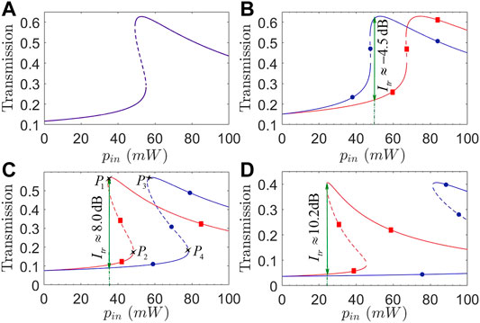
FIGURE 2. (Color online) Transmission coefficients T31 (red squares) and T13 (blue circles) against input power pin with (A) J23/2π = 1.725 GHz; (B) J23/2π = 2.0 GHz; (C) J23/2π = 1.4 GHz; (D) J23/2π = 1.0 GHz. Solid and dashed parts of each curve refer to stable and unstable regions, respectively. Other parameters are Δ1/2π = Δ2/2π = 4.5 GHz, Δ3/2π = 1.5 GHz, g/2π = 0.9 MHz, ωm/2π = 10 GHz, and J12/2π = 3.0 GHz, except those at the beginning of Section 3.
Comparing Eqs 8, 12, it is easy to see that the transmission non-reciprocity will be attained as long as we have U13 ≠ U31, which requires not only a broken impedance-matching condition but also U = g2/ωm ≠ 0. Thus, it is essential to examine in Figure 3 different effects of optomechanical coupling strength g and mechanical frequency ωm on transmission coefficients T31 and T13 plotted against input power pin. Figures 3A,B show that as g is enhanced by one order, pin required for observing the transmission non-reciprocity (in the bistable region where T13 and T31 work in the lower and upper branches, respectively) is reduced by two orders without changing the maximal isolation ratio Itr ≈ 10.2 dB. That means the observed transmission non-reciprocity exhibits an inverse dependence on input power pin and optomechanical coupling strength g. Figures 3C,D further show that the non-reciprocal region in terms of pin is not so sensitive to ωm though this region can be enlarged in the case of a larger ωm. It is more important to note that the upper branches of T31 and T13 may not be always stable and a larger ωm is helpful to reduce the unstable regions. These findings tell us how to choose g and ωm for attaining a wide enough non-reciprocal region corresponding to low enough input powers.
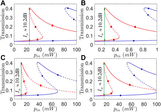
FIGURE 3. (Color online) Transmission coefficients T31 (red squares) and T13 (blue circles) against input power pin with (A) g/2π = 0.9 MHz; (B) g/2π = 9.0 MHz; (C) ωm/2π = 4.5 GHz; (D) ωm/2π = 6.5 GHz. Solid and dashed parts of each curve refer to stable and unstable regions, respectively. Other parameters are the same as in Figure 2, except J23/2π = 1.0 GHz.
Considering that the driving field and relevant optical modes are easy to be modulated in frequency, we plot in Figure 4 transmission coefficients T31 and T13 as a function of input power pin for different detunings Δ1 and Δ3. We can see from Figures 4A,B that the isolation ratio may be evidently improved in a wider non-reciprocal region by choosing a slightly larger Δ1 to well suppress the lower branches of T31 and T13, while leaving the upper branches unchanged yet in magnitude. To be more specific, we have Itr ≈ 6.1 dB for pin = 14 mW with Δ1/2π = 3.5 GHz, while Itr ≈ 13.1 dB for pin = 35 mW with Δ1/2π = 5.5 GHz. Figures 4C,D show instead that a significant increase of Δ3, though can result in a wider non-reciprocal region, will not change the isolation ratio too much as the upper and lower branches are suppressed to the roughly same extent. We also note from Figure 4B that the upper branch of T31 starts to become unstable at pin ≳ 140 mW for Δ1 = 5.5 GHz. It is thus clear that detunings Δ1 and Δ3 play different roles in manipulating the transmission non-reciprocity and can be jointly modulated for observing an ideal transmission non-reciprocity with larger isolation ratios and well suppressed lower branches for moderate input powers.
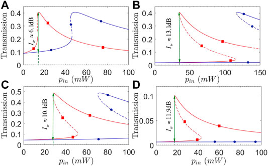
FIGURE 4. (Color online) Transmission coefficients T31 (red squares) and T13 (blue circles) against input power pin with (A) Δ1/2π = 3.5 GHz; (B) Δ1/2π = 5.5 GHz; (C) Δ3/2π = 0.1 GHz; (D) Δ3/2π = 6.0 GHz. Solid and dashed parts of each curve refer to stable and unstable regions, respectively. Other parameters are the same as in Figure 2, except J23/2π = 1.0 GHz.
3.2 Non-Reciprocal Transmission Against Detuning
We first plot in Figure 5 transmission coefficients T31 and T13 as a function of detuning Δ1 for different input powers pin. As the input power is very low (i.e., pin = 0.1 mW), Figure 5A shows that T31 and T13 overlap well with a symmetric peak centered at Δ1 ≈ (J12 + J23)/2 = 2 GHz, therefore leading to a vanishing transmission non-reciprocity. This can be attributed to the fact that both Eqs 8, 12 reduce to
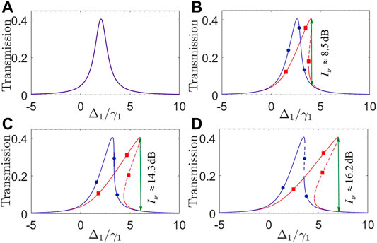
FIGURE 5. (Color online) Transmission coefficients T31 (red squares) and T13 (blue circles) against detuning Δ1 with (A) pin = 0.1 mW; (B) pin = 20 mW; (C) pin = 40 mW; (D) pin = 50 mW. Solid and dashed parts of each curve refer to stable and unstable regions, respectively. Other parameters are Δ2/2π = 4.5 GHz, Δ3/2π = 1.5 GHz, g/2π = 0.9 MHz, ωm/2π = 10 GHz, J12/2π = 3.0 GHz, and J23 = 1.0 GHz, except those at the beginning of Section 3.
Then we examine different effects of optical coupling strengths J12 and J23 by plotting in Figure 6 transmission coefficients T31 and T13 against detuning Δ1. Figures 6A,B show that a slight increase in J12 will result in an evidently identical rising of T31 and T13 but leaving their peaks roughly unchanged in position. The main difference lies in that the upper branch of T31 in Figure 6A exhibits a wider stable region than that in Figure 6B, indicating that a larger J12 helps to suppress quantum fluctuations arising from the non-linear optomechanical interaction. On the other hand, Figures 6C,D show that a slight increase in J23 can also result in an evidently identical rising of T31 and T13, but their peaks become evidently closer to each other, leading to a narrowing of the non-reciprocal bistable region as well as a reduction in the isolation ratio. These findings tell that a moderate J23 and a larger J12 are appropriate for attaining non-reciprocal bistable regions of wide enough stable upper branches and large enough isolation ratios.
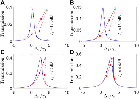
FIGURE 6. (Color online) Transmission coefficients T31 (red squares) and T13 (blue circles) against detuning Δ1 with (A) J12/2π = 1.0 GHz; (B) J12/2π = 1.3 GHz; (C) J23/2π = 1.0 GHz; (D) J23/2π = 1.3 GHz. Solid and dashed parts of each curve refer to stable and unstable regions, respectively. Other parameters are the same as in Figure 5, except pin = 20 mW.
Finally, we examine different effects of mechanical frequency ωm and optomechanical coupling strength g by plotting in Figure 7 transmission coefficients T31 and T13 against detuning Δ1. Comparing Figures 7A,B, we can see that both T31 and T13 remain unchanged in their peak values but clearly become more inclined toward Δ1 > 0 so as to yield wider bistable regions, with the increase in g. This then results in a wider non-reciprocal transmission region considering that T31 is much more sensitive to g and thus exhibits a much wider bistable region than T13. Figures 7C,D show however that an increase in ωm is helpful to reduce the unstable region of T31 in its upper branch but meanwhile also results in a reduction of the bistable regions for both T31 and T13. These findings tell that one should choose a lower ωm and a higher g to enhance the non-linear optomechanical interaction required for attaining wider non-reciprocal transmission regions of high isolation ratios.
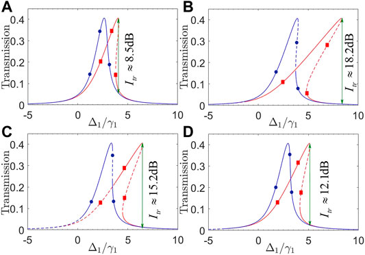
FIGURE 7. (Color online) Transmission coefficients T31 (red squares) and T13 (blue circles) against detuning Δ1 with (A) g/2π = 0.9 MHz; (B) g/2π = 1.6 MHz; (C) ωm/2π = 4.5 GHz; (D) ωm/2π = 6.5 GHz. Solid and dashed parts of each curve refer to stable and unstable regions, respectively. Other parameters are the same as in Figure 5, except pin = 20 mW.
In figures, the bistable transmission non-reciprocity occurs as the two curves for T31 and T13 do not overlap in each plot. It is thus appropriate to roughly determine a non-reciprocal bandwidth as the absolute difference of two values of pin or Δ1 corresponding, respectively, to the peak of T31 and that of T13. This non-reciprocal bandwidth is a few or tens of mW in Figures 2–4, while several times of γ1 in Figures 5–7, depending on relevant parameters like J12, J23, g, and ωm. Note also that a dynamic reciprocity, referring to the fact that a (weak) backward noise, can also be transmitted with little loss in the presence of a (strong) forward signal of high transmission, typically exists in the non-reciprocal systems based on optical non-linearities [59]. Accordingly, one limitation of our optomechanical system may be that it cannot break the dynamic reciprocity because the transmission non-reciprocity arises from a bistable non-linearity. This is clear by looking at Figures 2–4 where we have T31 ≠ T13 only when input power pin is not too small.
4 Conclusion
In summary, we have studied a four-mode optomechanical system for attaining the transmission non-reciprocity, in the presence of an optomechanically induced non-linearity, with respect to a driving field input from the left or right side. As the impedance-matching condition is broken, we find that transmission coefficients T31 and T13, plotted against input power pin or cavity detuning Δ1, may exhibit staggered bistable behaviors and therefore can work in the upper and lower branches, respectively. The isolation ratio of such a non-reciprocal transmission is viable to switch between Itr > 0 and Itr < 0 and can be improved in magnitude by modulating optical coupling strengths J12,23 and detunings Δ1,3 to suppress the lower branches or enhance the upper branches. It is also viable to broaden the non-reciprocal bistable region in terms of pin (Δ1) by modulating optomechanical coupling strength g and mechanical frequency ωm in addition to J12,23 and Δ1,3 (pin). But we should note that an increasing part of the upper branch may become unstable as the non-reciprocal region becomes wider, which restricts the tunable ranges of relevant parameters. Our results well extend the previous works on realizing non-reciprocal transmission in optomechanical systems and are instructive for designing non-reciprocal devices in optical networks based on coupled cavities.
Data Availability Statement
The original contributions presented in the study are included in the article/supplementary material; further inquiries can be directed to the corresponding authors.
Author Contributions
The idea was first conceived by J-HW. BJ was responsible for the physical modeling, the numerical calculations, and writing most of the manuscript. J-HW contributed to writing the manuscript, JW verified results of the theoretical calculation, and DY contributed to the discussion of the results. DQ provided technical support in computer simulation.
Funding
This work is supported by the National Natural Science Foundation of China (12074061, 11674049, and 11874004), Science Foundation of Education Department of Jilin Province (JJKH20200557KJ), and Nature Science Foundation of Science and Technology Department of Jilin Province (20210101411JC).
Conflict of Interest
The authors declare that the research was conducted in the absence of any commercial or financial relationships that could be construed as a potential conflict of interest.
Publisher’s Note
All claims expressed in this article are solely those of the authors and do not necessarily represent those of their affiliated organizations, or those of the publisher, the editors, and the reviewers. Any product that may be evaluated in this article, or claim that may be made by its manufacturer, is not guaranteed or endorsed by the publisher.
Acknowledgments
BJ thanks Luning Song, Yan Zhang, and Zhihai Wang for helpful discussions.
References
1. Teufel JD, Harlow JW, Regal CA, Lehnert KW. Dynamical Backaction of Microwave fields on a Nanomechanical Oscillator. Phys Rev Lett (2008) 101:197203. doi:10.1103/PhysRevLett.101.197203
2. Aspelmeyer M, Kippenberg TJ, Marquardt F. Cavity Optomechanics. Rev Mod Phys (2014) 86:1391–452. doi:10.1103/RevModPhys.86.1391
3. Liu Y-C, Hu Y-W, Wong C-W, Xiao Y-F. Review of Cavity Optomechanical Cooling. Chin Phys B (2013) 22:114213. doi:10.1088/1674-1056/22/11/114213
4. He B. Quantum Optomechanics beyond Linearization. Phys Rev A (2012) 85:063820. doi:10.1103/PhysRevA.85.063820
5. Cao C, Mi S-C, Gao Y-P, He L-Y, Yang D, Wang T-J, et al. Tunable High-Order Sideband Spectra Generation Using a Photonic Molecule Optomechanical System. Sci Rep (2016) 6:1–8. doi:10.1038/srep22920
6. Xiong X-R, Gao Y-P, Liu X-F, Cao C, Wang T-J, Wang C. The Analysis of High-Order Sideband Signals in Optomechanical System. Sci China Phys Mech Astron (2018) 61:1–4. doi:10.1007/s11433-017-9187-2
7. Shi H-Q, Xie Z-Q, Xu X-W, Liu N-H. Unconventional Phonon Blockade in Multimode Optomechanical System. Acta Phys Sin (2018) 67:044203. doi:10.7498/aps.67.20171599
8. Marinković I, Wallucks A, Riedinger R, Hong S, Aspelmeyer M, Gröblacher S. Optomechanical bell Test. Phys Rev Lett (2018) 121:220404. doi:10.1103/PhysRevLett.121.220404
9. Xu H, Lai D-G, Qian Y-B, Hou B-P, Miranowicz A, Nori F. Optomechanical Dynamics in the PT - and Broken- PT -symmetric regimes
10. Vitali D, Gigan S, Ferreira A, Böhm HR, Tombesi P, Guerreiro A, et al. Optomechanical Entanglement between a Movable Mirror and a Cavity Field. Phys Rev Lett (2007) 98:030405. doi:10.1103/PhysRevLett.98.030405
11. Chen R-X, Shen L-T, Yang Z-B, Wu H-Z, Zheng S-B. Enhancement of Entanglement in Distant Mechanical Vibrations via Modulation in a Coupled Optomechanical System. Phys Rev A (2014) 89:023843. doi:10.1103/PhysRevA.89.023843
12. Liao J-Q, Wu Q-Q, Nori F. Entangling Two Macroscopic Mechanical Mirrors in a Two-Cavity Optomechanical System. Phys Rev A (2014) 89:014302. doi:10.1103/PhysRevA.89.014302
13. Yan X-B. Enhanced Output Entanglement with Reservoir Engineering. Phys Rev A (2017) 96:053831. doi:10.1103/PhysRevA.96.053831
14. He Q, Ficek Z. Einstein-podolsky-rosen Paradox and Quantum Steering in a Three-Mode Optomechanical System. Phys Rev A (2014) 89:022332. doi:10.1103/PhysRevA.89.022332
15. Zhang X-L, Bao Q-Q, Yang M-Z, Tian X-S. Entanglement Characteristics of Output Optical fields in Double-Cavity Optomechanics. Acta Phys Sin (2018) 67:104203. doi:10.7498/aps.67.20172467
16. Poot M, Herre SJ. Mechanical Systems in the Quantum Regime. Phys Rep (2012) 511:273–335. doi:10.1016/j.physrep.2011.12.004
17. He B, Yang L, Lin Q, Xiao M. Radiation Pressure Cooling as a Quantum Dynamical Process. Phys Rev Lett (2017) 118:233604. doi:10.1103/PhysRevLett.118.233604
18. Chen H-J, Mi X-W. Normal Mode Splitting and Cooling in strong Coupling Optomechanical Cavity. Acta Phys Sin (2011) 60:124206–244. doi:10.7498/aps.60.124206
19. Li Y, Wu L-A, Wang Z-D. Fast Ground-State Cooling of Mechanical Resonators with Time-dependent Optical Cavities. Phys Rev A (2011) 83:043804. doi:10.1103/PhysRevA.83.043804
20. Liu Z-Q, Hu C-S, Jiang Y-K, Su W-J, Wu H, Li Y, et al. Engineering Optomechanical Entanglement via Dual-Mode Cooling with a Single Reservoir. Phys Rev A (2021) 103:023525. doi:10.1103/PhysRevA.103.023525
21. Bai C, Hou B-P, Lai D-G, Wu D. Tunable Optomechanically Induced Transparency in Double Quadratically Coupled Optomechanical Cavities within a Common Reservoir. Phys Rev A (2016) 93:043804. doi:10.1103/PhysRevA.93.043804
22. Yan X-B. Optomechanically Induced Transparency and Gain. Phys Rev A (2020) 101:043820. doi:10.1103/PhysRevA.101.043820
23. Lü H, Wang C, Yang L, Jing H. Optomechanically Induced Transparency at Exceptional Points. Phys Rev Appl (2018) 10:014006. doi:10.1103/PhysRevApplied.10.014006
24. Hou B-P, Wei L-F, Wang S-J. Optomechanically Induced Transparency and Absorption in Hybridized Optomechanical Systems. Phys Rev A (2015) 92:033829. doi:10.1103/PhysRevA.92.033829
25. Qu K, Agarwal GS. Phonon-mediated Electromagnetically Induced Absorption in Hybrid Opto-Electromechanical Systems. Phys Rev A (2013) 87:031802. doi:10.1103/PhysRevA.87.031802
26. Zhang J-Q, Li Y, Feng M, Xu Y. Precision Measurement of Electrical Charge with Optomechanically Induced Transparency. Phys Rev A (2012) 86:053806. doi:10.1103/PhysRevA.86.053806
27. Brunner N, Cavalcanti D, Pironio S, Scarani V, Wehner S. Bell Nonlocality. Rev Mod Phys (2014) 86:419–78. doi:10.1103/RevModPhys.86.419
28. Lü X-Y, Jing H, Ma J-Y, Wu Y. PT-Symmetry-Breaking Chaos in Optomechanics. Phys Rev Lett (2015) 114:253601. doi:10.1103/PhysRevLett.114.253601
29. Margueritat J, Virgone-Carlotta A, Monnier S, Delanoë-Ayari H, Mertani HC, Berthelot A, et al. High-frequency Mechanical Properties of Tumors Measured by Brillouin Light Scattering. Phys Rev Lett (2019) 122:018101. doi:10.1103/PhysRevLett.122.018101
30. Song L-N, Zheng Q, Xu X-W, Jiang C, Li Y. Optimal Unidirectional Amplification Induced by Optical Gain in Optomechanical Systems. Phys Rev A (2019) 100:043835. doi:10.1103/PhysRevA.100.043835
31. Xu X-W, Song L-N, Zheng Q, Wang Z-H, Li Y. Optomechanically Induced Nonreciprocity in a Three-Mode Optomechanical System. Acta Phys Sin (2018) 98:063845. doi:10.1103/PhysRevA.98.063845
32. Zhang L-W, Li X-L, Yang L. Optical Nonreciprocity with Blue-Detuned Driving in Two-Cavity Optomechanics. Acta Phys Sin (2019) 68:170701–9. doi:10.7498/aps.68.20190205
33. Miri M-A, Ruesink F, Verhagen E, Alù A. Optical Nonreciprocity Based on Optomechanical Coupling. Phys Rev Appl (2017) 7:064014. doi:10.1103/PhysRevApplied.7.064014
34. Li E-Z, Ding D-S, Yu Y-C, Dong M-X, Zeng L, Zhang W-H, et al. Experimental Demonstration of Cavity-free Optical Isolators and Optical Circulators. Phys Rev Res (2020) 2:033517. doi:10.1103/PhysRevResearch.2.033517
35. Li B, Özdemir ŞK, Xu X-W, Zhang L, Kuang L-M, Jing H. Nonreciprocal Optical Solitons in a Spinning Kerr Resonator. Phys Rev A (2021) 103:053522. doi:10.1103/PhysRevA.103.053522
36. Verhagen E, Alù A. Optomechanical Nonreciprocity. Nat Phys (2017) 13:922–4. doi:10.1038/nphys4283
37. Lira H, Yu Z, Fan S, Lipson M. Electrically Driven Nonreciprocity Induced by Interband Photonic Transition on a Silicon Chip. Phys Rev Lett (2012) 109:033901. doi:10.1103/PhysRevLett.109.033901
38. Manipatruni S, Robinson JT, Lipson M. Optical Nonreciprocity in Optomechanical Structures. Phys Rev Lett (2009) 102:213903. doi:10.1103/PhysRevLett.102.213903
39. Gridnev VN. Nonreciprocal Reflection of Light from Antiferromagnets. Jetp Lett (1996) 64:110–3. doi:10.1134/1.567141
40. Lu X, Cao W, Yi W, Shen H, Xiao Y. Nonreciprocity and Quantum Correlations of Light Transport in Hot Atoms via Reservoir Engineering. Phys Rev Lett (2021) 126:223603. doi:10.1103/PhysRevLett.126.223603
41. Wang Y-P, Rao J-W, Yang Y, Xu P-C, Gui Y-S, Yao B-M, et al. Nonreciprocity and Unidirectional Invisibility in Cavity Magnonics. Phys Rev Lett (2019) 123:127202. doi:10.1103/PhysRevLett.123.127202
42. Lai D-G, Huang J-F, Yin X-L, Hou B-P, Li W, Vitali D, et al. Nonreciprocal Ground-State Cooling of Multiple Mechanical Resonators. Phys Rev A (2020) 102:011502. doi:10.1103/PhysRevA.102.011502
43. Khanikaev AB, Mousavi SH, Shvets G, Kivshar YS. One-way Extraordinary Optical Transmission and Nonreciprocal Spoof Plasmons. Phys Rev Lett (2010) 105:126804. doi:10.1103/PhysRevLett.105.126804
44. Fang K, Luo J, Metelmann A, Matheny MH, Marquardt F, Clerk AA, et al. Generalized Non-reciprocity in an Optomechanical Circuit via Synthetic Magnetism and Reservoir Engineering. Nat Phys (2017) 13:465–71. doi:10.1038/nphys4009
45. Dzyaloshinskii I, Papamichail EV. Nonreciprocal Optical Rotation in Antiferromagnets. Phys Rev Lett (1995) 75:3004–7. doi:10.1103/PhysRevLett.75.3004
46. Ni X, He C, Sun X-C, Liu X-P, Lu M-H, Feng L, et al. Topologically Protected One-Way Edge Mode in Networks of Acoustic Resonators with Circulating Air Flow. New J Phys (2015) 17:053016. doi:10.1088/1367-2630/17/5/053016
47. Yu H, Wang Z, Wu J-H. Entanglement Preparation and Nonreciprocal Excitation Evolution in Giant Atoms by Controllable Dissipation and Coupling. Phys Rev A (2021) 104:013720. doi:10.1103/PhysRevA.104.013720
48. Du L, Cai M-R, Wu J-H, Wang Z, Li Y. Single-photon Nonreciprocal Excitation Transfer with Non-markovian Retarded Effects. Phys Rev A (2021) 103:053701. doi:10.1103/PhysRevA.103.053701
49. Zhang S, Hu Y, Lin G, Niu Y, Xia K, Gong J, et al. Thermal-motion-induced Non-reciprocal Quantum Optical System. Nat Photon (2018) 12:744–8. doi:10.1038/s41566-018-0269-2
50. Xia K, Nori F, Min X. Cavity-free Optical Isolators and Circulators Using a Chiral Cross-Kerr Nonlinearity. Phys Rev Lett (2018) 121:203602. doi:10.1103/PhysRevLett.121.203602
51. Hu Y, Zhang S, Qi Y, Lin G, Niu Y, Gong S. Multiwavelength Magnetic-free Optical Isolator by Optical Pumping in Warm Atoms. Phys Rev Appl (2019) 12:054004. doi:10.1103/PhysRevApplied.12.054004
52. Paraïso TK, Kalaee M, Zang L, Pfeifer H, Marquardt F, Painter O. Position-squared Coupling in a Tunable Photonic crystal Optomechanical Cavity. Phys Rev X (2015) 5:041024. doi:10.1103/PhysRevX.5.041024
53. DeJesus EX, Kaufman C. Routh-hurwitz Criterion in the Examination of Eigenvalues of a System of Nonlinear Ordinary Differential Equations. Phys Rev A (1987) 35:5288–90. doi:10.1103/PhysRevA.35.5288
54. Paternostro M, Gigan S, Kim MS, Blaser F, Böhm HR, Aspelmeyer M. Reconstructing the Dynamics of a Movable Mirror in a Detuned Optical Cavity. New J Phys (2006) 8:107. doi:10.1088/1367-2630/8/6/107
55. Gardiner CW, Collett MJ. Input and Output in Damped Quantum Systems: Quantum Stochastic Differential Equations and the Master Equation. Phys Rev A (1985) 31:3761–74. doi:10.1103/PhysRevA.31.3761
56. Agarwal GS, Huang S. Optomechanical Systems as Single-Photon Routers. Phys Rev A (2012) 85:021801. doi:10.1103/PhysRevA.85.021801
57. Aldana S, Bruder C, Nunnenkamp A. Equivalence between an Optomechanical System and a Kerr Medium. Phys Rev A (2013) 88:043826. doi:10.1103/PhysRevA.88.043826
58. Fabre C, Pinard M, Bourzeix S, Heidmann A, Giacobino E, Reynaud S. Quantum-noise Reduction Using a Cavity with a Movable Mirror. Phys Rev A (1994) 49:1337–43. doi:10.1103/PhysRevA.49.1337
Keywords: transmission non-reciprocity, bistable non-linearity, cavity optomechanics, impedance-matching breaking, optical isolation
Citation: Jiang B, Yan D, Wang J, Qu D and Wu J-H (2022) Controlled Bistable Transmission Non-Reciprocity in a Four-Mode Optomechanical System. Front. Phys. 9:822694. doi: 10.3389/fphy.2021.822694
Received: 26 November 2021; Accepted: 20 December 2021;
Published: 25 January 2022.
Edited by:
Hui Yan, South China Normal University, ChinaReviewed by:
Keyu Xia, Nanjing University, ChinaJianming Wen, Kennesaw State University, United States
Copyright © 2022 Jiang, Yan, Wang, Qu and Wu. This is an open-access article distributed under the terms of the Creative Commons Attribution License (CC BY). The use, distribution or reproduction in other forums is permitted, provided the original author(s) and the copyright owner(s) are credited and that the original publication in this journal is cited, in accordance with accepted academic practice. No use, distribution or reproduction is permitted which does not comply with these terms.
*Correspondence: Jing Wang, cHdsMTIwN3dqQDE2My5jb20=; Jin-Hui Wu, amh3dUBuZW51LmVkdS5jbg==
 Bo Jiang
 Dong Yan2