- School of Computer and Information, Hefei University of Technology, Hefei, China
Polarimetric imaging has been studied and applied to the problem of visibility restoration in various scenarios such as haze, mist and underwater. Although studies have shown that under certain conditions, circular polarimetric imaging has certain advantages over linear polarimetric imaging, however, for a complex environment containing both scattering medium and object, the performance of linear and circular polarimetric imaging is affected by many factors. In this paper, the propagation of linear and circular polarized light in the scattering medium is theoretically analyzed, then the simulation experiments under different experimental conditions are carried out and the conclusions are summarized. In order to validate the simulation results, the measurement experiments are carried out in dynamic smoke scenarios with different smoke concentrations. The results show that, the propagation of the polarized light, especially the circular polarized light, is determined by medium conditions. Generally, both the linear and circular polarimetric imaging had an ability to reduce the image degradation caused by smoke, however, under some certain environment conditions, unlike the linear polarized channels, the difference between the orthogonal circular polarized channels may be approached or even reversed, which may limit the circular polarization-based difference imaging and visibility restoration performance.
1 Introduction
When the polarized light propagates in the scattering medium, it undergoes multiple scattering with particles, leading to randomization of its direction, phase, and polarization state [1]. Due to the differences of material, structure and shape between the object and the background, their polarization properties are significantly different. Polarimetric imaging can enhance the difference between the object area and the background medium and highlight the details of the object by measuring and processing the polarization information. Nowadays, Polarimetric imaging has been applied in fields like object detection [2–4], biomedical imaging [5, 6].
Existing studies have shown that polarization gating can eliminate the contribution of scattered photons that lose the original polarization information caused by multiple scattering, and retain the photons that experience few scattering times that maintain the original polarization state component, so as to improve the image contrast [7, 8]. In addition, the circular polarimetric imaging is implemented in some scenarios, due to its advantages over the linear polarization [9–11]. However, due to the polarization memory effect, the helicity of circular polarized light can be reversed in some cases [12, 13]. Therefore, the law of the propagation of circular polarized light in the medium is more complex than that of linear polarized light and the influence of polarization memory effect should be fully considered in application.
We study the propagation of polarized light in a mixed environment including medium and object. Thus, we should model the polarimetric scattering in the medium and the polarimetric reflection by object surface. Linear polarimetric imaging is widely used in research and application, but due to some advantages of circular polarimetric imaging, however, we are still interested in the performance of linear and circular polarimetric imaging under different experimental conditions. This paper first studies the propagation of linear and circular polarized light in scattering medium. On this basis, simulation experiments are implemented based on Monte Carlo simulation program and the variation of the intensity of orthogonal polarization channels affected by different factors are analyzed. In addition, in order to validate the simulation results, a polarization setup is built for measurement experiments and a series of experimental data of different polarization channels are collected and the results are analyzed. The results show that, the propagation of the polarized light, especially the circular polarized light, can be affected by the medium factors such as concentration, wavelength and distance. Generally, both the linear and circular polarimetric imaging had an ability to reduce the image degradation caused by smoke, however, under some certain environment conditions, unlike the linear polarized channels, the difference between the orthogonal circular polarized channels may be approached or even reversed, which may limit the circular polarization-based difference imaging and visibility restoration performance.
2 Simulation of the Propagation of Polarized Light in Mixed Medium
In order to fully understand the propagation of polarized light in mixed media, we developed a Monte Carlo based simulation program [14, 15], and studied the process of polarized light propagating in medium through a series of simulation experiments. The significance of carrying out the simulation experiments is that, the propagation of polarized light in real scenarios is affected by many factors, such as the wavelength, the particle size, the concentration, the refractive index and the thickness of medium. However, it is difficult to evaluate the impact of each factor and include all the factors in measurement experiments. Therefore, the simulation experiments can help us better understand the propagation of linear and circular polarized light in different medium conditions.
2.1 Theoretical Basis of Propagation of Polarized Light
For linear polarimetric imaging, numerous polarization-maintaining photons can be detected at the upper layer of the scattering medium [1, 7]. As the photons penetrate into the deeper layer, due to the multiple scattering, the photons lose their initial polarization state and become randomized [1]. Therefore, the polarization difference imaging is to eliminate multiple scattered photons, so as to highlight the details and contrast of the object area. In addition, for circular polarimetric imaging, after photons scattered at large angles or reflected by the object surface, their helicity will be reversed compared with the initial helicity, while photons scatter forward at small angles will maintain the helicity [16, 17]. Some studies also pointed out that the helicity reversal is related to the relative size of photon’s wavelength and medium particle size [12, 18]. However, in the environment containing both medium and target, the situation will become more complicated when the polarimetric scattering and reflection have to be considered simultaneously.
2.2 Structure of the Program
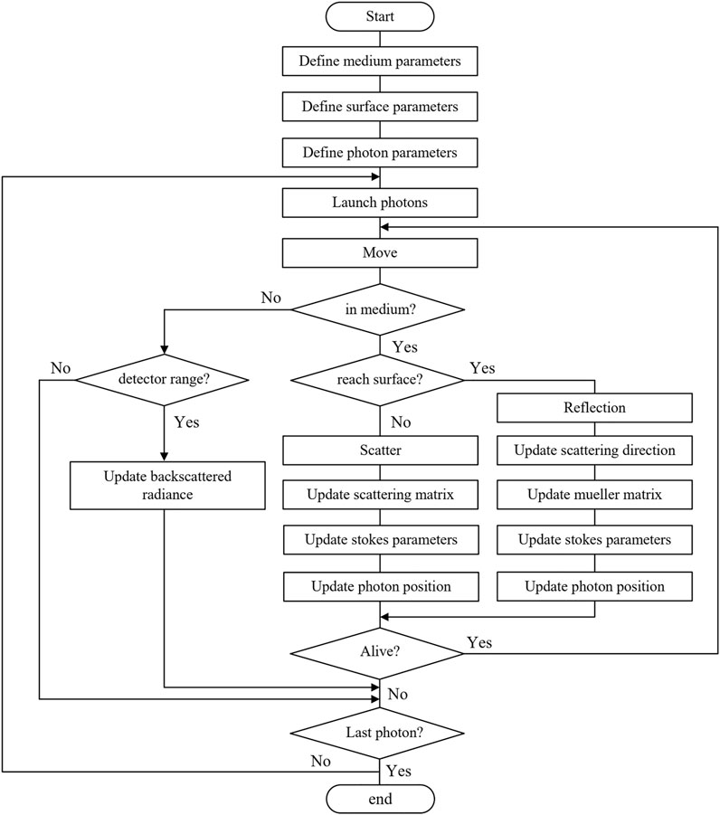
The scenario can be simplified as a mixture of the smoke medium in the upper layer and the object in the lower layer. Monte Carlo based simulation program can track the photon’s movement in the medium and update the photon’s polarization state. By counting the energy of backscattered photons on the receiving plane, the radiance of orthogonal polarization channels can be obtained.
The flow chart of the simulation program is shown in Figure 1, which mainly includes three main modules:
1) The scattering medium module can process the scattering of photons in the medium, and update the photon’s position, direction and polarization parameters after each movement;
2) The surface geometric modeling module can carry out geometric modeling on the object surface [19, 20], and update the photons’ reflection direction from the object surface;
3) The material modeling module can convert the object surface material into the corresponding optical parameters, generate the corresponding Mueller matrix [21, 22] and update the photons’ polarization state after reflection.
2.3 Simulation Experiments Under Different Experimental Conditions
The simulation experiments were carried out and the experimental conditions were set to match the measurement scenarios. The simulations focused on the radiance of orthogonal polarization channels in the environment containing medium and object. Because the particle size of the medium has a huge impact on the interaction between polarized photons and particles. Our simulation experiments chose two particle diameters, small-sized (0.2 μm) and large-sized (8.0 μm), and study the factors of concentration, wavelength and detection distance.
2.3.1 Effect of Concentration on the Propagation of Polarized Light
In the measurement experiment, the concentration of smoke is an important factor, affecting the polarimetric imaging performance. Theoretically, with the increase of smoke concentration, the number of particles per unit volume of the medium increases, the scattering coefficient of particles increases [23], the step size of photons generally decreases, the penetration depth of photons decreases, and the diffusion radius of photons increases. However, the propagation of polarized light with different initial polarization states is different. We simulated the backscattered intensity of linear and circular polarization with concentrations in the medium of small-sized and large-sized particles. The receiving plane was placed 10 cm above the object [24]. The smoke as the scattering medium was filled between the object and the receiving plane. The pencil beam light source was vertically incident into the environment at 10 cm above the object, and the refractive index of smoke particles at 0.630 μm was 1.57 + 0.4277i [25]. The refractive index of the object surface was set to 1.5, which corresponded to the material of the standard color chart (Spydercheckr) [26]. We set the medium concentration to a reasonable value to ensure that the calculated scattering coefficient was within the normal range in the actual scenarios [27]. The absorption coefficient was usually set to a small value [28]. The detailed simulation parameters were shown in Table 1.
The 3D distributions of backscattered intensity of polarization channels in the medium with small-sized particles were shown in Figure 2. The backscattered intensity at the centre of the plane was high because of the reflection, while the radiance at the periphery was low. The backscattered intensity at the centre of each distribution was marked in each subgraph. As shown in Figure 2A, for the horizontally linear polarized illumination, the horizontal linear polarized (co-polarized) light dominated the backscattered intensity, while for the right circular polarized illumination, an obvious helicity reversal phenomenon happened, that is, the left circular polarized light dominated the backscattered intensity, as shown in Figure 2B. Therefore, for the medium with small-sized (0.2 μm) particles, with the gradual increase of medium concentration, the intensity of co-polarized light and left circular polarized light decreased significantly, while that of cross-polarized light and right circular polarized light maintained at a very low level.
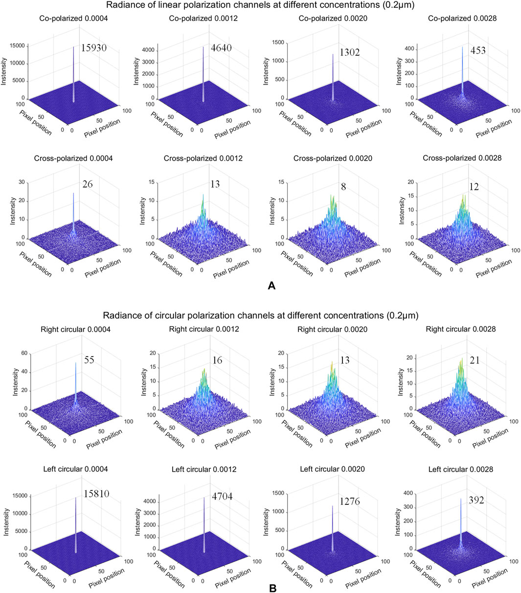
FIGURE 2. Radiance of polarization channels at different concentrations in the medium with small-sized particles (0.2 μm). (A) co-polarized and cross-polarized radiance, (B) right circular and left circular polarized radiance.
The 3D distributions of backscattered intensity of polarization channels in the medium with large-sized particles (8.0 μm) were shown in Figure 3. With the gradual increase of the concentration, the intensity of co-polarized and left circular polarization channel first decreased and then increased, while the intensity of cross-polarized and right circular polarization components increased significantly. Especially, the intensity of right-handed circular polarization component exceeded the left-handed polarization component when the concentration reached a certain degree. This was because when the medium concentration was low, the collision probability between photons and particles was low, backscattered photons were mostly reflected from the surface, or scattered at a large angle, so the helicity was mainly reversed. With the increase of medium concentration, the scattering coefficient of particles increased, the collision probability between photons and particles increased, and the multiple scattering of photons could be decomposed into multiple small angle scattering, therefore, the number of photons that maintained the original helicity increased as a whole. Therefore, for a particle polydisperse medium with different concentrations, the difference between the orthogonal linear polarized channels is maintained, while the difference between the orthogonal circular channels may be approached or even reversed.
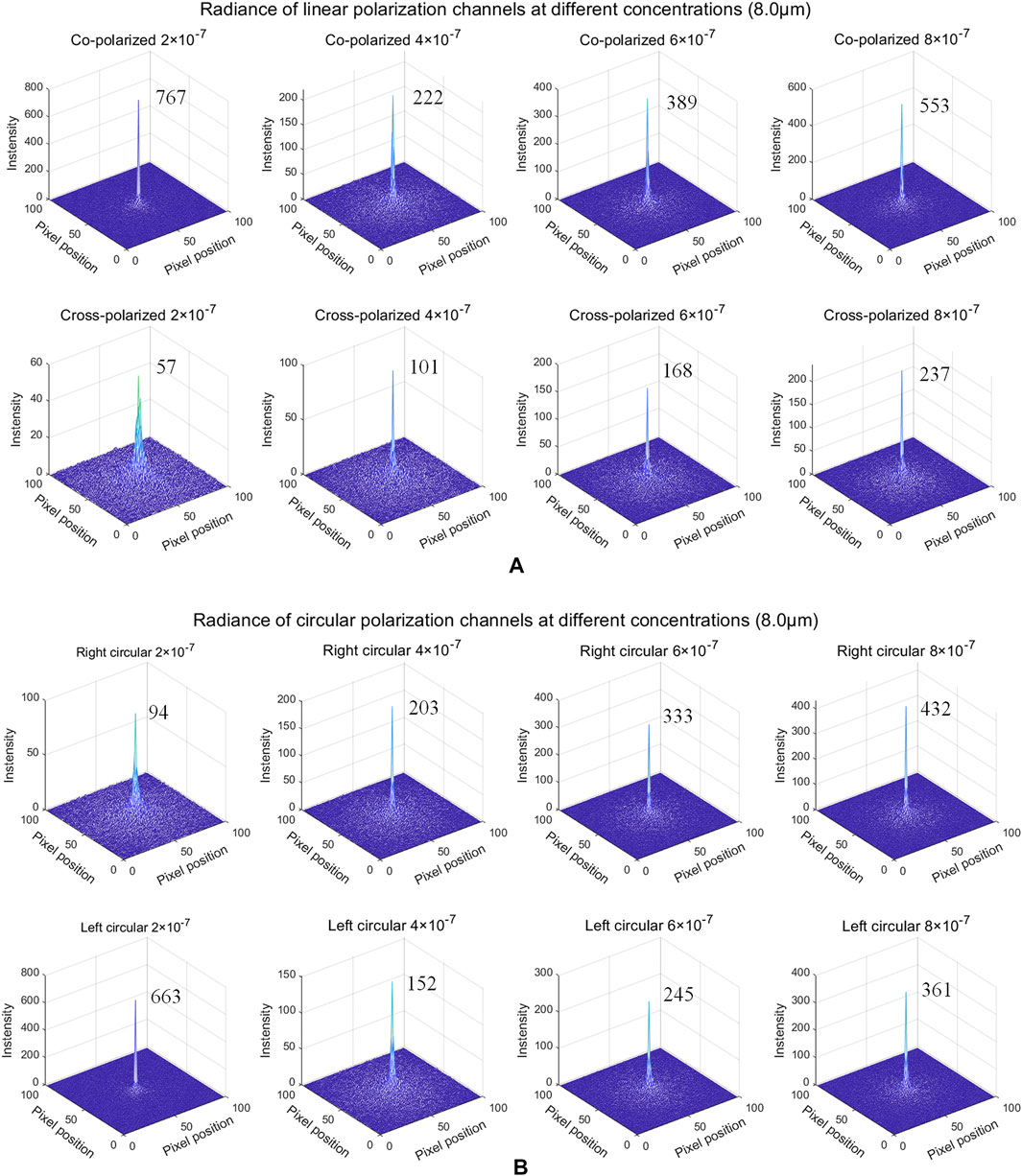
FIGURE 3. Radiance of polarization channels at different concentrations in the medium with large-sized particles (8.0 μm). (A) co-polarized and cross-polarized radiance, (B) right circular and left circular polarized radiance.
2.3.2 Effect of Wavelength on the Propagation of Polarized Light
In the measurement experiment, the wavelength also has an important impact on the results of polarimetric imaging. We carried out simulation experiments under different wavelengths and most of the simulation parameter settings were the same as the previous. As shown in Table 2, the concentration was set as a constant. The wavelength was selected in the range of visible light wavelength: 0.43, 0.48, 0.53, 0.58, 0.63 μm. The 3D distributions of backscattered intensity of polarization channels were shown in Figures 4, 5, respectively. For the medium with small-sized particles, the scattering coefficient of particles decreased gradually with the increase of initial wavelength, then the step size of photons generally increased, photons were easier to reach and reflect from the object surface, therefore for the co-polarized light and left circular channel, the intensity of the received backscattered light increased gradually, while the cross-polarized and right circular channel were insensitive to the variation of the wavelength, as shown in Figure 4. In addition, for the medium with large-sized particles, the scattering coefficient did not change significantly with the increase of wavelength, because the effective cross-section of the particle (proportional to scattering coefficient) [23] is large enough relative to the wavelength. Therefore, the intensity of all the polarization channels varied slightly, as shown in Figure 5, and the intensity of right circular component was higher than that of left circular component at all wavelengths. This was because in the medium with large-sized particles, the scattering coefficient of particles was high, the collision probability between photons and particles was large, and the multiple scattering of photons could be decomposed into multiple small angle scattering, so the number of photons that maintained the original helicity increased as a whole, and the number of photons reflected by the target surface decreased. Therefore, the difference between orthogonal linear polarized channels was more obvious compared with circular polarized channels.
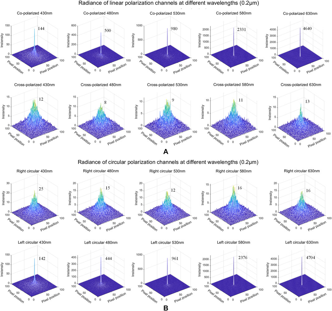
FIGURE 4. Radiance of polarization channels at different wavelengths in the medium with small-sized particles (0.2 μm). (A) co-polarized and cross-polarized radiance, (B) right circular and left circular polarized radiance.
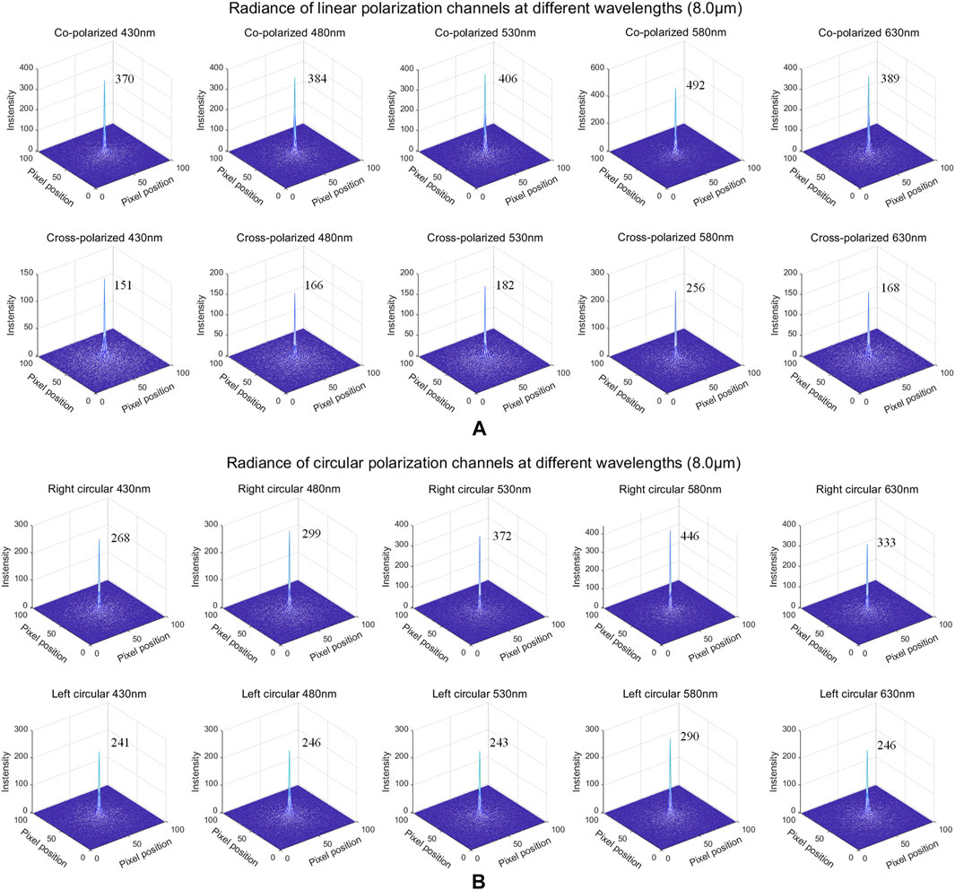
FIGURE 5. Radiance of polarization channels at different wavelengths in the medium with large-sized particles (8.0 μm). (A) co-polarized and cross-polarized radiance, (B) right circular and left circular polarized radiance.
2.3.3 Effect of Detection Distance on the Propagation of Polarized Light
In the measurement experiment, in the medium with uniform distribution, the distance between the detector and the object determines the thickness of the scattering medium. When the moving distance of photon in the medium exceeds its transport mean free path (MFP), the scattering direction will become randomized, which affecting the intensity of backscattered polarized channels [24]. Therefore, when studying the influence of detection distance on the propagation of polarized light, the photon’s transport MFP in the medium should be fully considered. For the medium with small-sized particles, the transport MFP was about 12.1 cm, while for the medium with large-sized particles, the transport MFP was about 6.9 cm. Therefore, for different medium environments, we set different detection distances for the simulations. The simulation parameters were listed in Table 3.
For the medium with small-sized particles, with the increase of the detection distance, the backscattered intensity of co-polarized and left circular polarized channel decreased significantly, while the intensity of cross-polarized and right circular polarized channel decreased slightly, as shown in Figure 6; while for the medium with large-sized particles, the backscattered intensity of all channels first decreased rapidly and the decrease amplitude of co-polarized and left circular polarized channels was much higher than that of cross-polarized and right circular polarized channels. With the gradual increase of detection distance and reaching the photon’s transport MFP, the right circular component exceeded the left circular component, as shown in Figure 7. This was because the receiving plate was gradually away from the target, the number of received helicity reversal photons due to object surface reflection was greatly reduced. As the distance continued to increase, the intensity of all channels remained nearly stable and did not change significantly with the increase of distance.
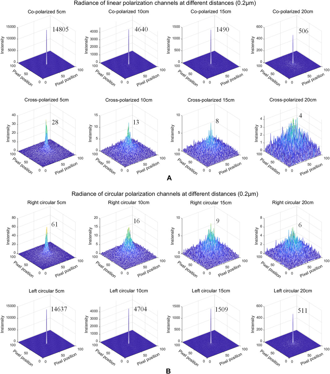
FIGURE 6. Radiance of polarization channels at different distances in the medium with small-sized particles (0.2 μm) (A) co-polarized and cross-polarized radiance, (B) right circular and left circular polarized radiance at 5 cm, 10 cm, 15 cm, 20 cm, respectively.
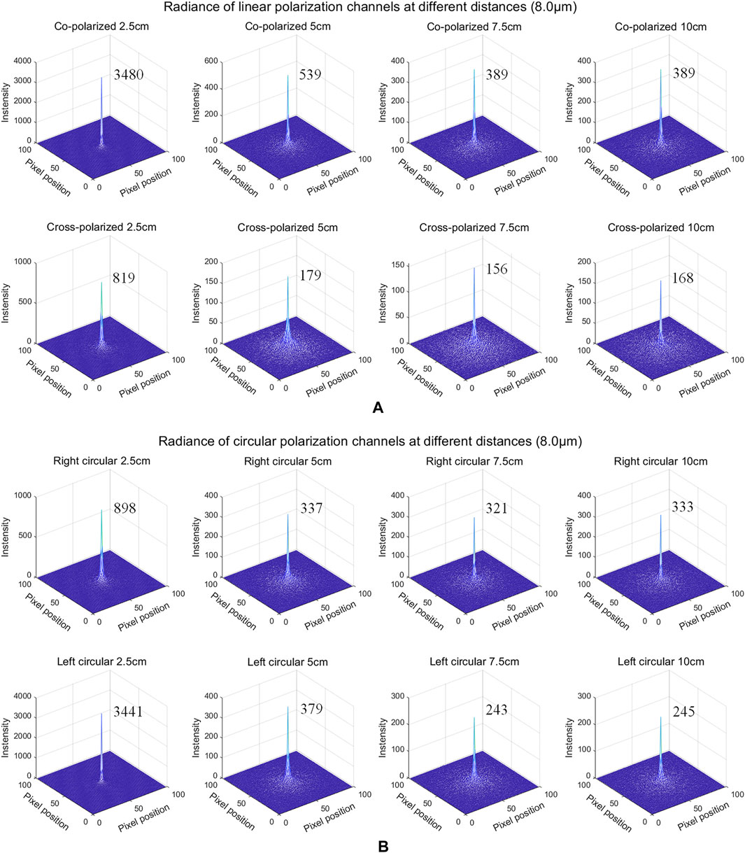
FIGURE 7. Radiance of polarization channels at different distances in the medium with large-sized particles (8.0 μm) (A) co-polarized and cross-polarized radiance, (B) right circular and left circular polarized radiance at 2.5 cm, 5 cm, 7.5 cm, 10 cm, respectively.
3 Polarization Based Visibility Restoration Method
In order to compare the performance of linear and circular polarization imaging on visibility recovery, we described the polarization-based visibility restoration method. The polarization-based image degradation model for orthogonal polarization state was written as:
where
The polarization difference calculation was implemented to estimate the parameters of the model. When the incident light penetrates the scattering medium and reaches the object layer, the polarization state of the photons will become randomized due to multiple scattering. We can assume that the polarization components
The reason for adding the absolute value calculation here is because for the circular polarization imaging, the helicity of the backscattered circular polarization state may be reversed. Then the transmission parameter of the degradation model could be estimated as:
The parameter A can be estimated by the proposed algorithm in [29].
In summary, the visibility restoration result could be estimated as:
4 Measurement Experiments
In order to validate the conclusion from simulation results, we carried out the polarimetric imaging experiment in the measurement scenario. We built a polarization imaging setup which can realize linear polarization and circular polarimetric imaging with nearly consistent conditions. A series of experimental data of different polarization channels were collected and the results were analyzed.
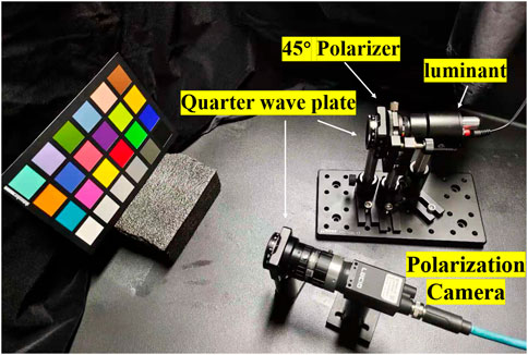
The experimental setup was shown in the Figure 8. The polarization state generator (PSG) was composed of an LED white illuminant GI-060411 (440–670 nm), a calibrated 45° linear polarizer and a calibrated quarter wave plate. The polarization state analyzer (PSA) was composed of a LUCID-TRI050S polarization camera and a quarter calibrated plate. Retaining or removing the quarter wave plate from the PSG can realize the switching between circular polarization and linear polarimetric imaging device. All the equipment was placed in a container with a black foam cover, and a fogger could generate smoke through heating the fog fluid and could inject into the container through a pipe. The SpyderCheckr was selected as the object, and two pairs of orthogonal backscattered polarization channels were collected. According to the parameters of the fogger and observation of the sedimentation velocities of particles [30], the smoke particle size was mainly in the range of 1–5 μm.
For circular polarization imaging, the axis direction of linear polarizer was at an angle of 45° with the fast axis or slow axis direction of the quarter wave plate, which could generate right or left circular polarized incident light, respectively. The fast axis of the quarter wave plate of PSA was placed along the vertical direction, and the intensities of left and right circular polarization were presented on the 45° and 135° channels of polarization camera, respectively. For linear polarization imaging, in order to minimize the variation of experimental conditions, the quarter wave plate of PSA was retained while that of PSG was removed. At this time, the incident light was 45° linear polarized light, and the intensities of linear co-polarized and cross-polarized were presented on 135° and 45° channels, respectively.
5 Result and Discussion
In the measurement experiment, the horizontal linear and right circular polarized light were used as the illumination. We filled the smoke into the container until the object signal was completely obscured by the scattering medium. With the settlement of smoke particles, the smoke concentration gradually decreased. We continuously captured the backscattered images of orthogonal polarization channels at different concentrations. We selected the intensity of orthogonal linear and circular polarization channels at four different concentrations, as shown in Figures 9, 10 respectively.
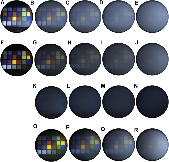
FIGURE 9. The results of linear polarimetric imaging: the intensity of co-polarized (A) and cross-polarized (F) in smoke-free scenario, the intensity of co-polarized (B–E) and cross-polarized (G–J) channels at four different concentrations, the corresponding polarization difference results (K–N) and visibility restoration results (O–R).
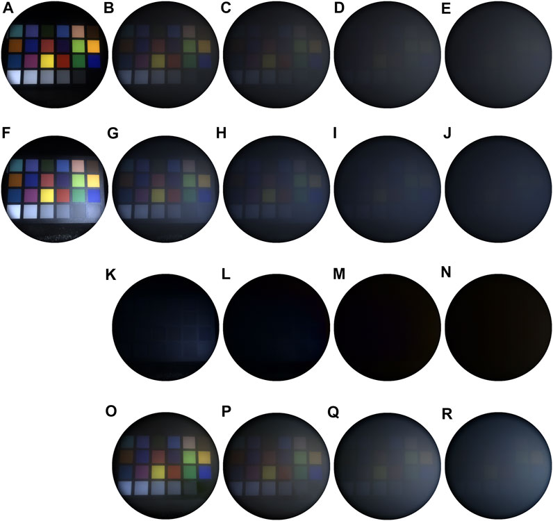
FIGURE 10. The results of circular polarimetric imaging: the intensity of right circular polarized (A) and left circular polarized (F) in smoke-free scenario, the intensity of right circular polarized (B–E) and left circular polarized (G–J) channels at four different concentrations, the corresponding polarization difference results (K–N) and visibility restoration results (O–R).
By comparing Figures 9A, F and Figures 10A, F, in the smoke free scenario, as the linear polarized incident light was reflected by the object, the co-polarized component was still dominant in the backscattered intensity, while for the circular polarized illumination, the helicity of the reflected circular polarized light was reversed, the intensity of left circular component was higher than that of right circular component.
In order to quantitatively analyzed the impact of the increase of smoke concentration on the intensity of each channel, we selected eight color blocks from the SpyderCheckr and quantitatively study their intensity varies with the smoke concentration, as shown in Figure 11. For the linear polarimetric imaging, as the smoke concentration increased, the intensity of color blocks with high RGB value (Primary Yellow, Apple Green) gradually decreased, because the signal is gradually obscured by the smoke, but the intensity of color blocks with low RGB value (Blueprint, Violet) gradually increased, because the smoke has a color of gray and it will lead to the increase of the intensity. A significant difference between orthogonal linear polarized channels could be observed, that was the co-polarized component was higher than that of cross-polarized component at all concentrations. However, for the circular polarimetric imaging, as the smoke concentration increased, the left circular component gradually decreased at all concentrations, because as the scattering coefficient increased, the photons were harder to reach the object, which then influence the intensity of left circular component generated by surface reflection. While for the right circular component, the trend was similar to that of linear polarized component, the photons relatively maintained their polarization state in a series of small angle scattering, and when the concentration reached a certain degree, the intensity exceeded the left circular component. The conclusions drawn by measurement experiments are consistent with those obtained from the simulations.
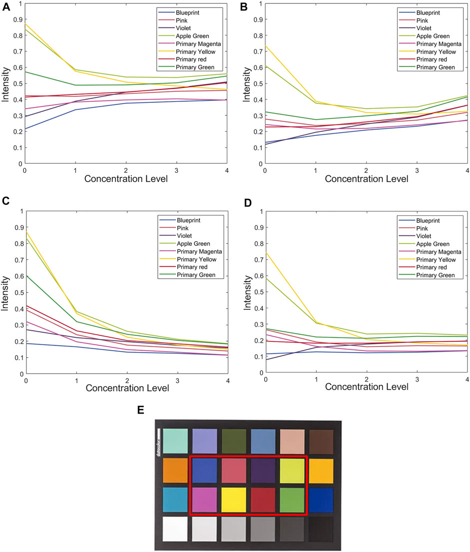
FIGURE 11. The intensity of orthogonal polarization channels at with different concentrations (A) co-polarized channel, (B) cross-polarized channel, (C) left circular polarized channel, (D) right circular polarized channel, (E) the selected eight color blocks in SpyderCheckr. The ordinate indicates the normalized backscattered intensity. The abscissa indicates the concentration level of scattering medium, (level) 0 represents a smoke-free scenario, and (level) 1–4 represents a gradual increase of the smoke concentration.
In addition, the visibility of the smoke images was restored based on the proposed method. The polarization difference results were shown in Figure 9 and Figures 10K–N, and the visibility restoration results under different concentrations were shown in Figure 9 and Figures 10O–R. Combining the qualitative and quantitative comparisons, it can be concluded that, under these concentration conditions, both the linear and circular polarimetric imaging had an ability to reduce the image degradation caused by smoke. For linear polarimetric imaging, the difference between co-polarized and cross-polarized component is maintained at different concentrations. However, as the smoke concentration increased, the left circular component gradually decreased while the right circular gradually increased, the polarization difference may be invalidated under certain medium scenarios and lead to failure of visibility restoration.
The main reasons for the differences between the simulations and the measurement experiments are as follows:
1) According to Malus’ law, the linear polarizer is not ideal and can be partially passed by the light with other polarization state, therefore, in the smoke free scenario, the difference between co-polarized and cross-polarized channel, right circular and left circular was not obvious as the simulation results.
2) The experimental scenario was a particle polydisperse medium, in addition, a white luminant with wide wavelength range was used in the measurement but usually a single wavelength for the simulation, which will lead to the difference between the simulation and measured results.
3) Since the removal of the quarter-wave plate led to the variation of the intensity of incident light, and the two imaging experiments were carried out successively, so it was not possible to ensure that the smoke concentration was at the same level. Therefore, we couldn’t directly compare the intensity of linear and circular polarization channels at different concentrations as in simulation experiments, and we also couldn’t directly compare the visibility restoration performance of linear and circular polarimetric imaging.
6 Conclusion
For polarimetric imaging in scattering medium, the selection of appropriate experimental conditions has an important impact on the polarimetric imaging. In order to study the propagation of linear and circular polarized light in the environment containing medium and object, based on the Monte Carlo simulation program, simulation experiments were carried out and the influence of factors such as concentration, wavelength and detection distance on the propagation of linear and circular polarized light were studied. In addition, the polarization setup was built to collect the intensity of linear and circular polarization channels under different medium concentrations. The variation of the intensity of color blocks with the concentration and the visibility restoration performance was studied and analyzed. The results show that in the scattering medium containing the object, factors such as concentration, wavelength and distance will change the number of scattering times of polarized light in the medium, thereby affecting the propagation of the polarized light. Generally, both the linear and circular polarimetric imaging had an ability to reduce the image degradation caused by smoke. For linear illumination, as the number of scattering increases, the backscattered intensity of the co-polarized component decreases, and the intensity of the cross-polarized component gradually increases, but the difference between orthogonal linear polarization channels is maintained but the difference will gradually decrease. For right circular illumination, in a medium with a small number of scattering times, the helicity of the reflected light from the object is reversed so that left circular polarized component will dominate the backscattered light. As the number of scattering times increases, the left circular component continues to decrease while that of the right circular polarization gradually increases. However, under some certain conditions, right circular component may approach or exceed the left circular component, which may limit the circular polarization-based difference imaging and visibility restoration performance.
Data Availability Statement
The original contributions presented in the study are included in the article/supplementary material, further inquiries can be directed to the corresponding author.
Author Contributions
DW was responsible for writing the manuscript and completing experiments. XW was responsible for assisting in relevant experiments and analyzing the results. PP was responsible for assisting in the simulation experiments. JG was responsible for the research content and theoretical guidance.
Conflict of Interest
The authors declare that the research was conducted in the absence of any commercial or financial relationships that could be construed as a potential conflict of interest.
The handling editor declared a past collaboration with one of the authors DW.
Publisher’s Note
All claims expressed in this article are solely those of the authors and do not necessarily represent those of their affiliated organizations, or those of the publisher, the editors and the reviewers. Any product that may be evaluated in this article, or claim that may be made by its manufacturer, is not guaranteed or endorsed by the publisher.
Acknowledgments
Support is acknowledged from China Scholarship Council (No. 201906690041), National Natural Science Foundation of China (61971177, 62171178).
References
1. Gnanatheepam E, Kanniyappan U, Dornadula K, Prakasarao A, Singaravelu G. Polarization Gating Technique Extracts Depth Resolved Fluorescence Redox Ratio in Oral Cancer Diagnostics. Photodiagnosis Photodyn Ther (2020) 30:101757. doi:10.1016/j.pdpdt.2020.101757
2. Schechner YY, Narasimhan SG, Nayar SK. Polarization-Based Vision Through Haze. Appl Opt (2003) 42(3):511–25. doi:10.1364/AO.42.000511
3. Treibitz T, Schechner YY. Active Polarization Descattering. IEEE Trans Pattern Anal Mach Intell (2009) 31(3):385–99. doi:10.1109/TPAMI.2008.85
4. Schechner YY, Karpel N. Recovery of Underwater Visibility and Structure by Polarization Analysis. IEEE J Oceanic Eng (2005) 30(3):570–87. doi:10.1109/JOE.2005.850871
5. Qi J, Elson DS. Mueller Polarimetric Imaging for Surgical and Diagnostic Applications: a Review. J Biophotonics (2017) 10(8):950–82. doi:10.1002/jbio.201600152
6. Qi J, Elson DS. A High Definition Mueller Polarimetric Endoscope for Tissue Characterisation. Sci Rep (2016) 6(1):1–11. doi:10.1038/srep25953
7. Sridhar S, Da Silva A. Enhanced Contrast and Depth Resolution in Polarization Imaging Using Elliptically Polarized Light. J Biomed Opt (2016) 21(7):071107. doi:10.1117/1.JBO.21.7.071107
8. Lizana A, Van Eeckhout A, Adamczyk K, Rodríguez C, Escalera JC, Garcia-Caurel E, et al. Polarization Gating Based on Mueller Matrices. J Biomed Opt (2017) 22(5):1. doi:10.1117/1.JBO.22.5.056004
9. Ni X, Alfano RR. Time-resolved Backscattering of Circularly and Linearly Polarized Light in a Turbid Medium. Opt Lett (2004) 29(23):2773–5. doi:10.1364/OL.29.002773
10. Kartazayeva SA, Ni X, Alfano RR. Backscattering Target Detection in a Turbid Medium by Use of Circularly and Linearly Polarized Light. Opt Lett (2005) 30(10):1168–70. doi:10.1364/OL.30.001168
11. Nothdurft R, Yao G. Applying the Polarization Memory Effect in Polarization-Gated Subsurface Imaging. Opt Express (2006) 14(11):4656–61. doi:10.1364/OE.14.004656
12. Kuzmin V, Meglinski I. Helicity Flip of the Backscattered Circular Polarized Light. In: Biomedical Applications of Light Scattering IV. San Francisco, CA: International Society for Optics and Photonics (2010). p. 75730Z. doi:10.1117/12.841193
13. Kim AD, Moscoso M. Backscattering of Circularly Polarized Pulses. Opt Lett (2002) 27(18):1589–91. doi:10.1364/OL.27.001589
14. Ramella-Roman JC, Prahl SA, Jacques SL. Three Monte Carlo Programs of Polarized Light Transport into Scattering media: Part I. Opt Express (2005) 13(12):4420–38. doi:10.1364/OPEX.13.004420
15. Ramella-Roman JC, Prahl SA, Jacques SL. Three Monte Carlo Programs of Polarized Light Transport into Scattering media: Part II. Opt Express (2005) 13(25):10392–405. doi:10.1364/OPEX.13.010392
16. van der Laan JD, Wright JB, Scrymgeour DA, Kemme SA, Dereniak EL. Evolution of Circular and Linear Polarization in Scattering Environments. Opt Express (2015) 23(25):31874–88. doi:10.1364/OE.23.031874
17. Doronin A, Macdonald C, Meglinski I. Propagation of Coherent Polarized Light in Turbid Highly Scattering Medium. J Biomed Opt (2014) 19(2):025005. doi:10.1117/1.JBO.19.2.025005
18. Shukla P, Sumathi R, Gupta S, Pradhan A. Influence of Size Parameter and Refractive index of the Scatterer on Polarization-Gated Optical Imaging Through Turbid media. J Opt Soc Am A (2007) 24(6):1704–13. doi:10.1364/JOSAA.24.001704
19. Walter B, Marschner SR, Li H, Torrance KE. Microfacet Models for Refraction through Rough Surfaces. In: EGSR’07: Proceedings of the 18th Eurographics Conference on Rendering Techniques, Grenoble, France, June 25–27, 2007 (2007).
20. Heitz E. Understanding the Masking-Shadowing Function in Microfacet-Based BRDFs. J Comput Graph Tech (2014) 3(2):32–91.
21. Germer TA. Angular Dependence and Polarization of Out-of-Plane Optical Scattering from Particulate Contamination, Subsurface Defects, and Surface Microroughness. Appl Opt (1997) 36(33):8798–805. doi:10.1364/AO.36.008798
22. Germer TA. SCATMECH: Polarized Light Scattering C++ Class Library. (2021). Available from: https://www.nist.gov/publications/scatmech-polarized-light-scattering-c-class-library?pub_id=841413 (Accessed November 10, 2021).
23.OMLC. Definition and Units of Scattering Coefficient. (2021). Available from: https://omlc.org/classroom/ece532/class3/musdefinition.html (Accessed December 1, 2021).
24. Novikova T, Bénière A, Goudail F, De Martino A. Sources of Possible Artefacts in the Contrast Evaluation for the Backscattering Polarimetric Images of Different Targets in Turbid Medium. Opt Express (2009) 17(26):23851–60. doi:10.1364/OE.17.023851
25. Li S, Cheng X, Mei P, Lu S, Yang H, Zhang H. Multiple Scattering of Light Transmission in a Smoke Layer. Optik (2014) 125(9):2185–90. doi:10.1016/j.ijleo.2013.10.040
26.Wikipedia. List of Refractive Indices. (2021). Available from: https://en.m.wikipedia.org/wiki/List_of_refractive_indices (Accessed November 10, 2021).
27.Dieselnet. Smoke Density. (2021). Available from: https://dieselnet.com/calculator/smoke1.html (Accessed September 15, 2021).
28.Biophotonics. Cloud Based Monte Carlo Tool for Photon Transport. (2021). Available from: http://www.biophotonics.fi/ (Accessed November 8, 2021).
29. Berman D, Treibitz T, Avidan S. Air-light Estimation Using Haze-Lines. In: 2017 IEEE International Conference on Computational Photography (ICCP), Cluj-Napoca, Romania, June 29–July 1, 2017 (2017). p. 1–9. doi:10.1109/ICCPHOT.2017.7951489
30.Smokemachines. Particle Size & Settling Velocities. (2021). Available from: http://www.smokemachines.com/settling-velocities-particle-size.aspx (Accessed November 12, 2021).
Keywords: polarimetric imaging, propagation of polarized light, mixed medium, linear polarization, circular polarization
Citation: Wang D, Wang X, Pan P and Gao J (2022) Polarimetric Imaging in the Environment Containing Medium and Object. Front. Phys. 9:815360. doi: 10.3389/fphy.2021.815360
Received: 15 November 2021; Accepted: 13 December 2021;
Published: 11 January 2022.
Edited by:
Ji Qi, Imperial College London, United KingdomCopyright © 2022 Wang, Wang, Pan and Gao. This is an open-access article distributed under the terms of the Creative Commons Attribution License (CC BY). The use, distribution or reproduction in other forums is permitted, provided the original author(s) and the copyright owner(s) are credited and that the original publication in this journal is cited, in accordance with accepted academic practice. No use, distribution or reproduction is permitted which does not comply with these terms.
*Correspondence: Daqian Wang, ZC53YW5nMTlAaW1wZXJpYWwuYWMudWs=
 Daqian Wang
 Xin Wang