
95% of researchers rate our articles as excellent or good
Learn more about the work of our research integrity team to safeguard the quality of each article we publish.
Find out more
ORIGINAL RESEARCH article
Front. Phys. , 28 January 2022
Sec. Condensed Matter Physics
Volume 9 - 2021 | https://doi.org/10.3389/fphy.2021.774951
This article is part of the Research Topic Generation, Detection and Manipulation of Skyrmions in Magnetic Nanostructures View all 10 articles
 Takao Matsumoto1*
 Naoya Shibata1,2,3
Magnetic skyrmion is a particle-like swirling spin texture promising for future memory devices. The geometric confinement and artificial control of skyrmions are crucial for such practical applications. In a previous research, we developed a technique to confine skyrmions to simple geometric corrals, such as a rectangle and a triangle, composed of artificial surface pits with nanometer-scale dimensions fabricated by using a focused electron beam. The technique has a potential advantage of facilitating more complex geometries, which has not been fully explored yet. Here we directly visualize skyrmions confined to surface-pit corrals with several complex geometries by using differential phase contrast scanning transmission electron microscopy. We find that individual skyrmions are deformed not only in shape but also in size under a moderate-bias field. We also find that deformed skyrmionic spin textures with opposite polarities coexist in the zero-field condition. The present study provides a guide to confine skyrmions, which should be useful for future applications.
Magnetic skyrmion [1–5] is a particle-like swirling spin texture arising from the competition between Heisenberg and Dzyaloshinskii–Moriya (DM) exchange interactions [6, 7]. It attracts growing attention as it is promising for future innovative devices owing to its nanometer-scale dimensions and topological stability [8, 9]. In such practical applications, skyrmions are expected to be confined in nanostructures with various geometries so that the influence of such geometric confinement on the behaviors of skyrmions is essential. In modern magnetic recording technology, such as the bit patterned media technology [10], geometric confinement is one of the key techniques to increase the stability of the elemental spin textures and hence the density of recorded information. Geometric confinement of skyrmions has been studied by micromagnetic simulations, assuming simple geometries such as nanodisks [11–15] and constricted channels [16, 17]. To realize the geometric confinement of skyrmions in experiments, conventional microfabrication techniques were used to fabricate nanodisks [18–22], nano-strips [23–25], and holes/trenches [26, 27]. In these studies, complete physical edges were utilized to confine skyrmions. Partial physical edges like the surface nano-strips with various widths and thicknesses created by using focused gallium ion beam [28] are also effective to confine skyrmions. In addition, non-physical (chemical) edges were also shown to be effective to confine skyrmions. By using helium ion beam, the DM interaction in a localized region was modified to confine skyrmions in simple geometric shapes like nano-strips and squares [29]. Recently, it was demonstrated that skyrmions can be effectively confined in channels by fabricating stripes with modified magnetic properties in a single ferromagnetic film [30]. Alternatively, Zhang et al. [31] showed that skyrmions were directly created by scanning the surface of a specimen by a magnetic force microscopy (MFM) tip with bias field. Using the same technique, Ognev et al. [32] have demonstrated the creation of zero-bias-field skyrmion patterns with complex geometries, such as a toroid and an alphabet S. In a previous study [33], we demonstrated that even tiny surface pits with nanometer-scale dimensions fabricated by using a focused electron beam (surface-pit corral) are effective to confine stable skyrmion states. These unconventional techniques have the potential advantage of facilitating complex geometries that are difficult or even not feasible by conventional microfabrication techniques.
Unlike rigid particles, such as colloidal particles and atoms, skyrmions can change their shape. Such a deformation of individual skyrmions was first revealed in an in situ Lorentz transmission electron microscopy (TEM) study, demonstrating that a small uniaxial tensile strain induces a very large anisotropic deformation (elongation) of a skyrmion lattice (SkL) as well as individual skyrmions constituting the lattice [34]. We also found that individual skyrmions can flexibly change not only their shapes but also their sizes to accommodate the free volumes formed at the domain boundary cores of SkLs under the influence of the complete physical edges of a thin-plate specimen [35]. The domain boundary structure can be described by the periodic combination of fivefold-coordinated and sevenfold-coordinated structure units as frequently observed in real atomic crystals. Skyrmions at the center of fivefold-coordinated structure units are spatially compressed, while skyrmions at the center of sevenfold-coordinated structure units are spatially elongated compared with the regular circular skyrmions. Recently, such deformed skyrmions were shown to play significant roles in the spontaneous creation and annihilation of skyrmions [36]. Artificial control of such deformations (elongation and compression) of individual skyrmions is important from a viewpoint of practical applications as suggested by a recent proposal to utilize a skyrmion with an elliptical profile confined in a magnetic nanodisk as the qubits for quantum computing platforms [37]. On the other hand, artificial control of the swirling nature of skyrmions is also important from a viewpoint of practical applications. The swirling nature of a skyrmion is characterized by several parameters [21]: magnetic helicity γm, polarity p, and circularity c. The magnetic helicity is defined as γm = + and γm = − for a right-handed spin helix and a left-handed spin helix, respectively. Following the same definitions as commonly used to describe a magnetic vortex—a similar swirling spin texture—[38], skyrmions, with their out-of-plane magnetizations at the core pointing up and down, are defined by polarity p = +1 and p = −1, respectively, while skyrmions with their in-plane magnetizations rotating clockwise (CW) and counter-clockwise (CCW) around the core are defined by the circularity c = +1 and c = −1, respectively. The magnetic helicity is determined once a material is given, depending on the crystallographic chirality Γc and sign of the DM interaction, where Γc is defined as + and − for right-handed and left-handed crystallographic chirality, respectively [39, 40]. When the magnetic helicity is given, p is determined uniquely once c has been given and vice versa, depending on the direction of the bias magnetic field applied on a specimen. So far, several attempts to control the swirling parameters of skyrmions have been reported. A unique spin texture in a confined geometry called a target skyrmion, which was predicted in theoretical and numerical investigations [12, 19], was directly visualized by Lorentz TEM in a 160-nm-diameter nanodisk of FeGe [21]. In zero magnetic field, two types of target skyrmions [one is characterized by a combination of positive circularity (c = +1) and positive polarity (p = +1), while another is characterized by a combination of negative circularity (c = −1) and negative polarity (p = −1)] were observed as the material possesses the right-handed magnetic helicity (γm = +). The two stable ground states with opposite characteristics were demonstrated to switch each other by changing the direction of the perpendicular magnetic field applied on the thin-plate specimen. The polarity reversal of skyrmions was also feasible by thermal activation in a thin plate of barium hexaferrite [41] and by switching the magnetic helicity in a thin plate of Mn1 - xFexGe with varying compositions, resulting in the sign reversal of the DM interaction [42]. Theoretically, two degenerate skyrmion states characterized by opposite polarities can be created by applying an inclined magnetic pulse [43] that was used for magnetic vortex core reversal [35].
To investigate the deformations of individual skyrmions while distinguishing their swirling characteristics, direct real-space visualization techniques of individual skyrmions with high spatial resolutions, such as Lorentz TEM [5, 44], off-axis electron holography [45, 46], and differential phase contrast scanning TEM (DPC STEM) [33, 47], are powerful. DPC STEM is arguably the most powerful technique, particularly when the magnetic spin texture and various kinds of material defects, such as edges, grain boundaries, and surface pits, must be visualized simultaneously, as demonstrated by previous works [33, 35, 48–50]. Here we report skyrmion states confined to surface-pit corrals with complex geometries directly visualized in real-space with nanometer spatial resolution by using the DPC STEM technique.
A bulk polycrystalline β-Mn type Co8Zn8Mn4 was synthesized by Dr. Yeong-Gi So at Akita University from highly pure Co (99.99%), Zn (99.99%), and Mn (99.99%) using an electric furnace; the constituent elements with the nominal composition of Co8Zn8Mn4 were sealed in an evacuated silica tube, heated at 1,273 K for 12 h, subsequently cooled to 1,198 K at a cooling rate of 1 K/h, and annealed at 1,198 K for 72 h, followed by water quenching.
A (111) thin plate was fabricated from a bulk crystal by using an Ion Slicer (IS9001, JEOL, Ltd.). Prior to observation, the thin plate was further polished with a plasma cleaner (Solarus, Model 950, Gatan, Inc.). The typical thickness of the thin plate is estimated to be about 150 nm.
For DPC STEM observations, we used a STEM (JEM-2100F, JEOL, Ltd.) equipped with a probe-forming aberration corrector (CEOS, GmbH) and a Schottky field emission gun operated at 200 kV. This microscope was equipped with a segmented annular all-field detector which was described in a literature in detail [51]. When observing magnetic skyrmion, the objective lens was switched off, and the illumination system was adjusted to obtain a probe size of about 3.5 nm with a probe-forming aperture semi-angle of 0.426 mrad. A perpendicular magnetic field was applied by weakly exciting the objective lens, and the field strength was calibrated by using a magnetic field measuring specimen holder equipped with three Hall-probe sensors. Even when the objective lens of the microscope is completely switched off and demagnetized several times, a small remnant perpendicular magnetic field of around 20 mT is applied on the thin-plate specimen. We use “zero-field” to refer to this experimental condition throughout the manuscript. For a probe size of 3.5 nm, the detector ranges are 0.346–0.520 and 0.78–1.35 mrad for DPC images and annular dark-field (ADF) images, respectively. To record images, we used pixel dwell time as long as 1 ms in the present study to obtain sufficient contrast at room temperature.
The same STEM (JEM-2100F, JEOL, Ltd.) used for DPC STEM observations was also used to fabricate surface-pit corrals with the objective lens strongly excited to form a smaller probe size (< 1 nm) with increasing probe current. A customized program written at the University of Tokyo was used to control the scanning of the focused electron beam to create a sequence of surface pits forming complex geometric patterns. The details of the nature of surface pits are described elsewhere [33].
For practical applications, magnetic skyrmions stable at room temperature are highly desirable. To observe stable magnetic skyrmions at room temperature (296 K), we use a (111) thin plate of Co8Zn8Mn4 [33, 52] with the critical temperature (Tc) of 300 K. Due to the decreased magnetization at room temperature (T / Tc ∼ 0.99 for T = 296 K), however, the contrast of skyrmions at room temperature is much lower than that at a low temperature (T / Tc ∼0.32 for T = 95 K). A longer pixel dwell time than usual is hence required at room temperature to record images with sufficient contrast. Figure 1 shows a comparison of DPC STEM images of SkLs in a thin plate of Co8Zn8Mn4 at room temperature (296 K) under the perpendicular magnetic field of 40 mT (Figures 1A–D) and those at a low temperature (95 K) under the perpendicular magnetic field of 60 mT (Figures 1E–H) recorded with the same pixel dwell time (640 μs). In the reconstructed in-plane magnetic induction, as shown in Figures 1A,B, individual skyrmions with negative circularity (CCW, c = −1) are directly visualized at room temperature. Note that the in-plane magnetic induction as a color map as shown in Figure 1A is disturbed by diffraction contrast due to the inevitable bending of the thin-plate specimen. The swirling in-plane magnetic induction with negative circularity is correctly reconstructed only for a few individual skyrmions in the lattice. In magnetic helicity images [35] (Figure 1C), however, skyrmions with negative circularity are visualized as bright particles without an apparent influence of the diffraction contrast. In the ADF image (Figure 1D), no obvious contrast other than the diffraction contrast is observed, which proves that no apparent structural defect exists in the field-of-view of the thin-plate specimen. Since the bias magnetic field is in the down direction as indicated by the crossed circle symbols in the figure, the polarity of skyrmions as visualized in Figures 1A–C is inferred as positive (p = +1). It follows that the magnetic helicity of the specimen is left-handed (γm = −). Individual skyrmions are mostly circular in shape. In contrast, strongly deformed skyrmions are observed at a temperature of 95 K (Figure 1E–G). No contrast indicating the existence of apparent structural defects is observed again in the ADF image (Figure 1H), ensuring that the deformations are not induced by structural defects in the specimen. Note that skyrmions are deformed not only in shape but also in size as indicated by several yellow shapes, compared with the less deformed circular skyrmion as indicated by a red circle in Figure 1G. It appears that the deformed skyrmions prefer a few orientations rather than random orientations, which can be ascribed to the weak crystal magnetic anisotropy in the (111) plane at 95 K. Actually, in a previous Lorentz TEM study [53], it was reported that circular skyrmions created by 70 mT field-cooling at 280 K were deformed into the bar- or L-shaped form in a (001) thin plate of Co8Zn8Mn4 when the specimen was field-cooled to a temperature of an extremely low temperature (6 K). The elongation direction nearly aligned along the magnetic easy axis <100>, which is induced by the enhancement of magnetocrystalline anisotropy at the low temperature. Deformed skyrmions are also created at room temperature by geometric confinement as will be shown below.
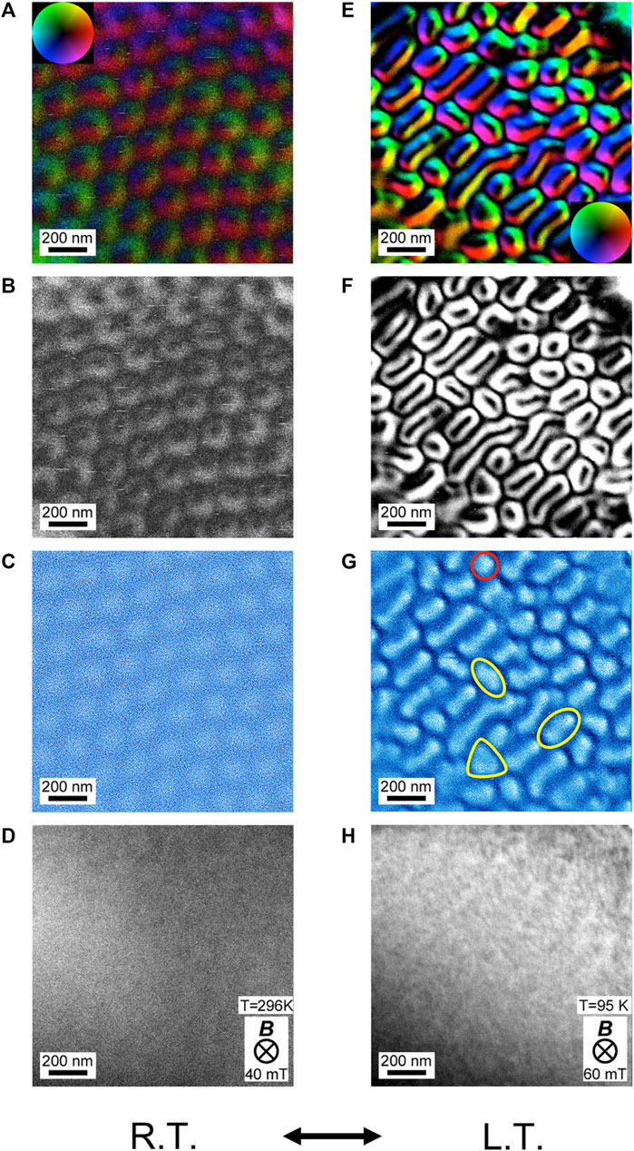
FIGURE 1. Differential phase contrast scanning TEM images of skyrmion lattices in a thin plate of Co8Zn8Mn4 at room temperature (296 K) (A–D) and at a low temperature (95 K) (E–H). (A,E) In-plane magnetic induction as a color map and (B,F) intensity. (C,G) Magnetic helicity images [35] and (D,H) simultaneously acquired annular dark-field images. The same pixel dwell time of 640 μs was used to record these images. Perpendicular magnetic fields of 40 and 60 mT are applied at 296 and 95 K, respectively. Yellow shapes indicate several deformed skyrmions, not only in shape but also in size, while a red circle indicates less deformed circular skyrmions in (G).
First, we briefly review skyrmion states confined to surface-pit corrals with three simple geometries—a square, a circle, and a triangle—as schematically shown in Figures 2A,F,K respectively. The ADF images of the fabricated corrals are shown in Figures 2B,G,L. The edge length of the square, diameter of the circle, and edge length of the equilateral triangle are equally 440 nm. Here only helicity images are shown because the reconstructed in-plane magnetic induction maps are severely disturbed by diffraction contrast (data not shown). We obtained images in the zero-field condition several times, which resulted in slightly different images. Zero-field 1 and zero-field 2 correspond to two independent experimental results. Note that the two states were not created as a result of any specific hysteresis loop as described in a literature [54], but their difference was entirely due to randomness. For the square corral, two elongated skyrmions in two orthogonal (horizontal and vertical) directions can be seen in the two zero-field conditions (Figures 2C,D), while four circular skyrmions are created under the perpendicular magnetic field of 60 mT (Figure 2E). Inside the circular corral, on the other hand, strongly deformed spin textures are created in the zero-field condition (Figures 2H,I), which are consistent with the spin textures confined in a disk fabricated by conventional microfabrication technique reported in previous publications [20, 21]. Under the perpendicular magnetic field of 60 mT, three isolated circular skyrmions are created (Figure 2J). In contrast, inside the triangular corral, single isolated circular skyrmion is stabilized even in the zero-field condition (Figures 2M,N) as well as under the perpendicular magnetic field of 60 mT (Figure 2O). Since skyrmions are created by the superposition of helical spin textures propagating along multiple directions defined by q-vectors, these experimental results can be understood by considering the q-vectors defined by the boundaries as indicated by yellow arrows in Figures 2B,G,L. The triangular geometry is compatible with the triple-q mechanism [3] to create skyrmions. Triangular confinement of skyrmions attracted attention in several literatures, too [55, 56]. Note that, some 40 years ago, magnetic vortices stabilized in cobalt fine particles with several geometric shapes were studied by using electron holography technique in a pioneering work directed by Tonomura [57]. They reported that an isolated magnetic vortex is stabilized both in a triangular platelet with an edge length of 250 nm and in a hexagonal platelet with an edge length of 200 nm under zero-bias field. Single magnetic vortex was observed at the center of both fine particles owing to the influence of the complete physical edges.
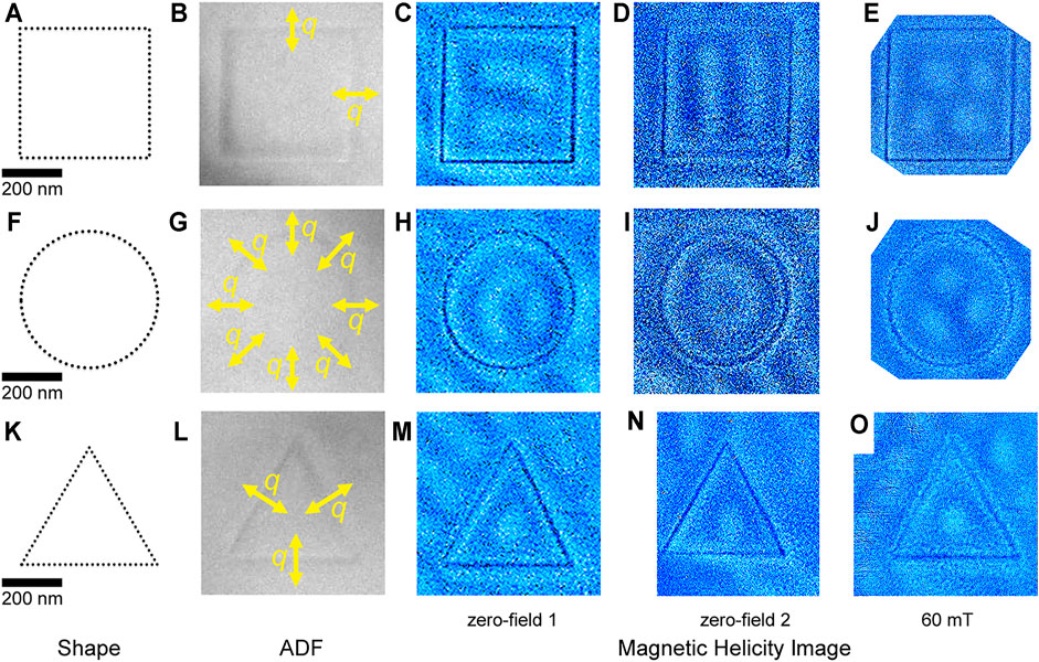
FIGURE 2. Skyrmion states confined to surface-pit corrals with three simple geometries. Schematics of (A) a square, (F) a circle, and (K) a triangular corral. Annular dark-field images of fabricated corrals with a square (B), a circle (G), and a triangle geometry (L) by using a focused electron beam. The edge length of the square, diameter of the circle, and edge length of the equilateral triangle are equally 440 nm. Several q-vectors defined by each corral are indicated by yellow arrows in (B), (G), and (L), respectively. Magnetic helicity images of spin textures confined to a square corral (C–E), a circular corral (H–J), and a triangular corral (M–O) are shown. Spin textures in two independent zero-field conditions (C,D,H,I,M,N) and under the perpendicular magnetic field of 60 mT (E,J,O) are shown. Skyrmions are displayed as bright particles. Pixel dwell time is 1 ms.
Now, we show skyrmion states confined to surface-pit corrals with a complex geometry. Figure 3 shows the confinement of skyrmions to surface-pit corrals with two nested curved boundaries (track and field) as schematically shown in Figure 3A. We fabricated two track and field corrals with two different sizes as shown in the ADF image (Figure 3B). The track width of the smaller corral and that of the larger corral are 420 and 630 nm, respectively. In the smaller (S) track and field corral, a linear chain and a curved chain of single skyrmions are created in the field area and track area, respectively (Figures 3C–F). In the larger (L) track and field, a small hexagonal array of skyrmions is created in the field area, while three strings of skyrmions are aligned in the track area (Figures 3G–J). Note that some skyrmions appear strongly elongated as indicated by the white arrows in Figures 3I–L, creating a domain boundary. Here we emphasize that skyrmions are aligned under the influence of surface-pit corrals working like physical edges with the complex geometry.
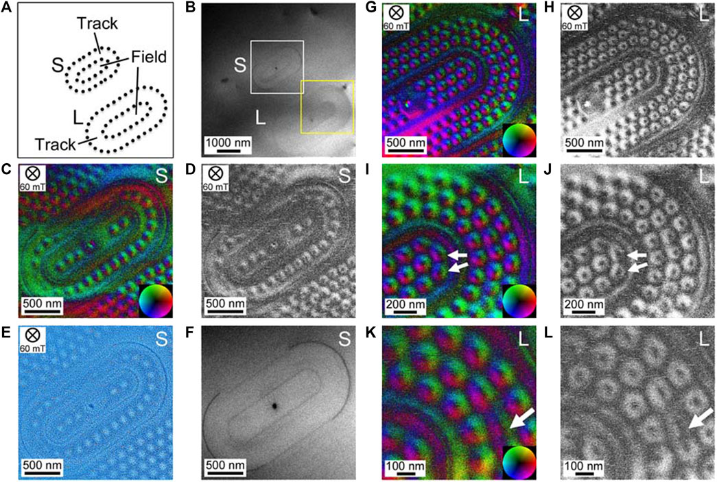
FIGURE 3. Confinement of skyrmions to surface-pit corrals defined by two nested curved boundaries (track and field). (A) Schematic of the two corrals with smaller and larger sizes. (B) Annular dark-field (ADF) image of the two corrals fabricated by a focused electron beam on the surface of the thin-plate specimen. The track width of the smaller corral and that of the larger corral are 420 and 630 nm, respectively. (G) In-plane magnetic induction as a color map and (H) intensity obtained in the area indicated by a white square in (B). (C) Magnetic helicity image and (D) ADF image of the smaller corral. (I) In-plane magnetic induction as a color map and (J) intensity confined in the larger corral. Only the field-of-view as indicated by the yellow square in (B) is shown. (E) In-plane magnetic induction as a color map and (F) intensity confined in the larger corral at a higher magnification. (K) In-plane magnetic induction as a color map and (L) intensity confined in the larger corral at a higher magnification. Elongated skyrmions are indicated by white arrows in (E,F,K,L). The pixel dwell time is 1 ms. The S and L letters at the top-right corner of each image indicate the smaller and the larger corrals, respectively.
Next, we demonstrate skyrmion states confined to surface-pit corrals with a more complex geometry—five interlaced rings of equal dimensions (Olympic symbol) as schematically shown in Figure 4A. Figure 4B shows the ADF image of the fabricated pattern on the thin-plate specimen. The diameter of each ring is 630 nm. Figures 4C–E show skyrmions confined to surface-pit corrals with the Olympic symbol geometry under the perpendicular magnetic field of 60 mT. Skyrmions are strongly deformed not only in shape but also in size as indicated by the yellow shapes in the magnetic helicity image (Figure 4E). Not only elongated skyrmions but also expanded skyrmions are observed. Figures 4F–H show skyrmions confined to surface-pit corrals with the Olympic symbol geometry under the perpendicular magnetic field of 93 mT. As the perpendicular magnetic field is increased, elliptical skyrmions transform into more circular ones, but with apparent deformations as indicated by the yellow shapes in the magnetic helicity image (Figure 4H). Note that the distribution of skyrmions is symmetric (3-2-2-2-3 from left to right). The numbers of skyrmions confined in the five defined regions are proportional to each area. After a slight change of the specimen orientations, however, the distribution of skyrmions under the same intensity of perpendicular magnetic field (93 mT) changes, as shown in Figures 4I–K. The numbers of skyrmions vary arbitrarily among the five separated regions (3-2-1-2-4 from left to right). The skyrmions are again strongly deformed not only in shape but also in size as indicated by the yellow shapes in the magnetic helicity image (Figure 4K). An apparently expanded skyrmion is observed in the confined area indicated as δ in Figure 4I. A compressed circular skyrmion is also observed as indicated by a red circle in Figure 4K. A gallery of several deformed individual skyrmions extracted from Figure 4 is shown in Figure 5. Individual skyrmions can conform to the areas surrounded by complex boundaries, deforming into elliptical and triangular shapes with expansions (Figure 5A), long and short elliptical shapes (Figures 5B,C), an expanded elliptical shape (Figure 5D) as well as three short elliptical shapes and a compressed circular shape (Figure 5E). A rough estimate of the expansion of the skyrmion as shown in Figure 5D is larger than 25%. The compression of the smallest skyrmion as shown in Figure 5E, in contrast, is not so large (10%). Both elongation and compression of skyrmions were observed in a previous study investigating the domain boundary core formed in a SkL in a thin plate of FeGe1 - xSix [35]. The ratio of compression was roughly estimated to be as small as 10%, while the ratio of elongation was as large as 60%. Furthermore, for the geometrically confined skyrmions to a triangular surface-pit corral [33] as shown in Supplementary Figure S1, the ratio of expansion is evaluated as 25%. More quantitative evaluations, however, should be necessary in future works. Additional demonstrations of skyrmion states confined to surface-pit corrals with interlaced rings geometry are given in Supplementary Figure S2.
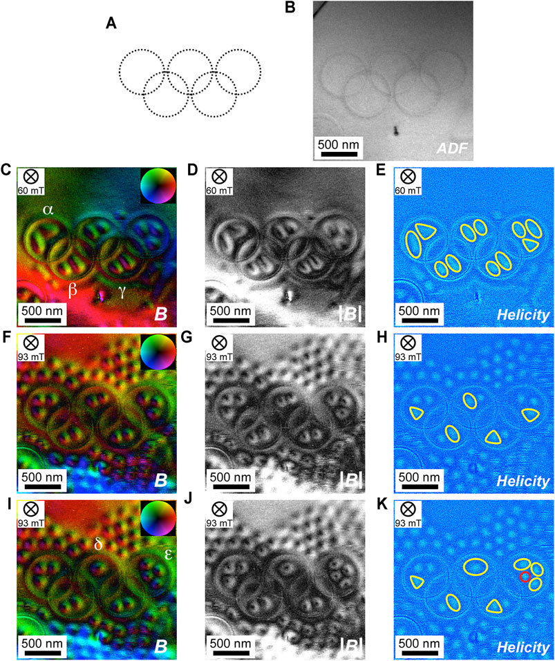
FIGURE 4. Individual skyrmions confined to a surface-pit corral with a complex geometry (Olympic symbol) under moderate-bias fields. (A) A schematic of the five interlaced rings of equal dimensions (630 nm in diameter). (B) Annular dark-field image of the fabricated pattern on the thin-plate specimen. (C–E) Individual skyrmions under the perpendicular magnetic field of 60 mT. (F–H) Individual skyrmions under the perpendicular magnetic field of 93 mT. (I–K) Individual skyrmions under the perpendicular magnetic field of 93 mT with a slight change of the specimen orientation from the one shown in (F–H). (C,F,I) In-plane magnetic induction as a color map, (D,G,J) as intensity, and (E,H,K) magnetic helicity image. Several deformed skyrmions, not only in shape but also in size, are indicated by yellow shapes in the magnetic helicity images in (E,H,K). A compressed circular skyrmion is indicated by a red circle in (K). Pixel dwell time is 1 ms.
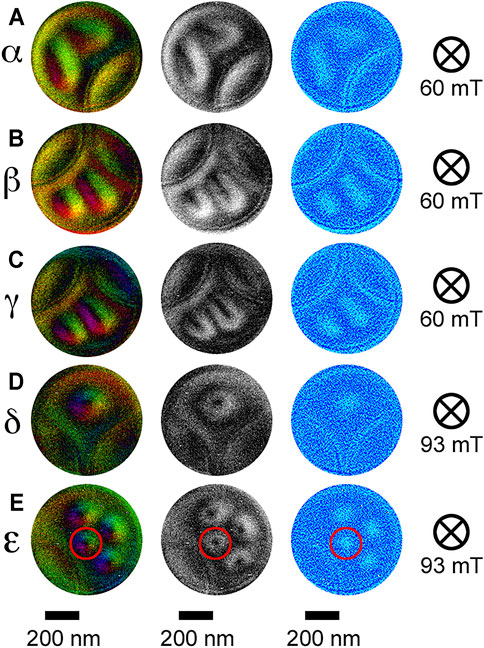
FIGURE 5. Gallery of several deformed individual skyrmions arbitrarily extracted from Figure 4. From left to right, in-plane magnetic induction as a color map, in-plane magnetic induction as intensity, and magnetic helicity image are shown. (A–E) The confined areas as indicated by α-ε in the color maps correspond to the areas indicated in Figures 4C,I. A compressed circular skyrmion is indicated by a red circle in (E).
Lastly, we demonstrate spin textures confined to surface-pit corrals with the Olympic symbol geometry in the zero-field condition. In-plane magnetic induction reconstructed from DPC STEM signals is shown as a color map in Figure 6A and as intensity in Figure 6B. Figures 6C,D, show the magnetic helicity image and ADF image, respectively. The color map at a low magnification (Figure 6A) is severely disturbed by diffraction contrast. The boxed region in Figures 6A–D is observed at a higher magnification in Figures 6E–H. Here horizontal and vertical deflection images are shown in Figures 6G,H, respectively, instead of magnetic helicity and ADF images. The color map at a higher magnification (Figure 6E) is not so disturbed by diffraction contrast. Note that spin textures appearing as elliptical skyrmions with opposite circularities (and hence opposite polarities) coexist as indicated by a blue oval arrow rotating CCW and a red oval arrow rotating CW in Figure 6E. The yellow-boxed region of the horizontal deflection image (Figure 6G) is enlarged as shown in Figure 6I. The corresponding left-handed helical spin texture is schematically shown in Figure 6J. Note that the position of the surface-pit corral is slightly shifted from the domain boundary (indicated by target mark symbols), which suggests that the connection between the spin texture and surface-pit corral is loosely (softly) coupled rather than the tightly (hardly) coupled connection between the spin texture and complete physical edge in conventional microfabrication techniques. It should be possible to control the connection between loose (soft) and tight (hard) by adjusting the physical parameters of surface pits, such as diameter, depth, and interdistance. The plausible skyrmionic spin textures confined to the surface-pit corral with Olympic symbol geometry are schematically shown in Figure 6K. Such a polarity reversal of skyrmionium spin textures in a microfabricated nanodisk was also reported in a previous literature [21]. We emphasize that the polarity reversal is only possible under a very weak perpendicular magnetic field (∼20 mT). It is not clear whether the skyrmionic spin textures are actually skyrmions with opposite polarities or not. To confirm, we must check that the stray field directions at the centers of skyrmionic spin textures are actually reversed by using other experimental techniques, such as MFM, because the DPC STEM technique is not sensitive to perpendicular magnetic field (parallel with the incident electron beam).
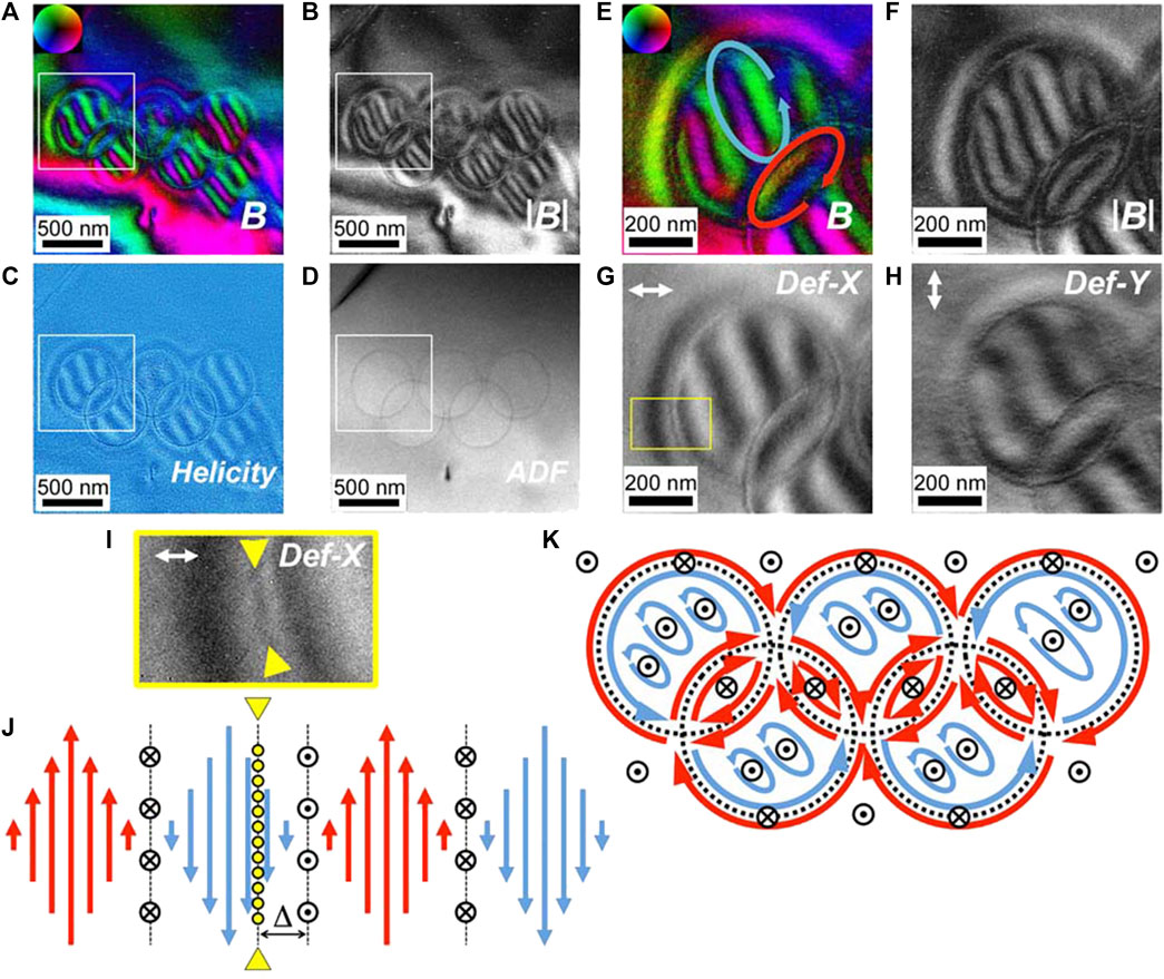
FIGURE 6. Zero-field skyrmionic spin texture confined to a surface-pit corral with a complex geometry (Olympic symbol). (A) In-plane magnetic induction as a color map and (B) as intensity, (E) magnetic helicity image, and (F) annular dark-field (ADF) image of the whole pattern. The boxed region in (A–D) is observed at a higher magnification in (C,D,G,H). Note that the horizontal and vertical deflection images are shown in (G) and (H), respectively, instead of the magnetic helicity and ADF images. (I) The boxed area indicated by a yellow rectangle in (G) is enlarged. The surface-pit corral is indicated by a pair of yellow arrowheads. (J) Schematic of the left-handed helical spin texture corresponding to (I) across the surface-pit corral. The surface-pit corral is displayed as a yellow dotted line, which is indicated by a pair of yellow arrowheads. (K) A simplified schematic of the plausible skyrmionic spin texture confined in the Olympic symbol in zero-field condition. The target mark symbols and crossed circle symbols indicate upward and downward directions, respectively.
In conclusion, we have investigated spin textures confined to surface-pit corrals with complex geometries by using the DPC STEM technique. We have found that individual skyrmions are aligned with elongation under the influence of the complex boundary defined by the surface-pit corrals. In addition, we have found that individual skyrmions are deformed not only in shape (elongation) but also in size (both expansion and compression) as influenced by the complex boundaries under a moderate-bias field. Furthermore, we have found that deformed skyrmionic spin textures with opposite polarities may coexist in zero-field condition. It is suggested that the connection between the spin texture and surface-pit corral is loosely (softly) coupled rather than the tightly (hardly) coupled connection found between the spin texture and complete physical edge in conventional microfabrication techniques. It should be possible to control the connection between loose (soft) and tight (hard) by adjusting the physical parameters of surface pits, such as diameter, depth, and interdistance. We hope that our experimental observations stimulate theoretical and micro-magnetic simulation studies on the controlled deformation of skyrmions. We also hope that the present study provides a guidance to arrange skyrmions with controlled swirling parameters, which should be explored for future applications.
The original contributions presented in the study are included in the article/Supplementary Material. Further inquiries can be directed to the corresponding author.
TM designed and conducted the TEM/STEM experiments, processed the images, and wrote the manuscript. NS developed the aberration-corrected DPC STEM system, directed the study, and read and commented on the manuscript.
A part of this work was supported by the Japan Science and Technology Agency SENTAN grant number JPMJSN14A1. A part of this work was conducted at the Research Hub for Advanced Nano Characterization, The University of Tokyo, supported under “Nanotechnology Platform” (project no. 12024046) sponsored by MEXT, Japan. TM and NS acknowledge support from the JSPS KAKENHI grant number 20H05659. NS acknowledges support from the JSPS KAKENHI grant number 19H05788.
The authors declare that the research was conducted in the absence of any commercial or financial relationships that could be construed as a potential conflict of interest.
All claims expressed in this article are solely those of the authors and do not necessarily represent those of their affiliated organizations or those of the publisher, the editors, and the reviewers. Any product that may be evaluated in this article or claim that may be made by its manufacturer is not guaranteed or endorsed by the publisher.
The authors acknowledge M. Nakabayashi at The University of Tokyo for her help in the thin plate preparation. We thank Dr. Y. Kohno and Dr. H. Sawada at JEOL, Ltd., for their assistance in DPC STEM. We thank Prof. Yeong-Gi So at Akita University for preparing the bulk crystal of Co8Zn8Mn4. Lastly, we acknowledge Prof. Y. Ikuhara at The University of Tokyo for his support and assistance throughout the study.
The Supplementary Material for this article can be found online at: https://www.frontiersin.org/articles/10.3389/fphy.2021.774951/full#supplementary-material
1. Skyrme THR. A Unified Field Theory of Mesons and Baryons. Nucl Phys (1962) 31:556–69. doi:10.1016/0029-5582(62)90775-7
2. Rößler UK, Bogdanov AN, Pfleiderer C. Spontaneous Skyrmion Ground States in Magnetic Metals. Nature (2006) 442:797–801. doi:10.1038/nature05056
3. Mühlbauer S, Binz B, Jonietz F, Pfleiderer C, Rosch A, Neubauer A, et al. Skyrmion Lattice in a Chiral Magnet. Science (2009) 323:915–9. doi:10.1126/science.1166767
4. Münzer W, Neubauer A, Adams T, Mühlbauer S, Franz C, Jonietz F, et al. Skyrmion Lattice in the Doped semiconductorFe1−xCoxSi. Phys Rev B (2010) 81:041203. doi:10.1103/PhysRevB.81.041203
5. Yu XZ, Onose Y, Kanazawa N, Park JH, Han JH, Matsui Y, et al. Real-space Observation of a Two-Dimensional Skyrmion crystal. Nature (2010) 465:901–4. doi:10.1038/nature09124
6. Dzyaloshinsky I. A Thermodynamic Theory of "weak" Ferromagnetism of Antiferromagnetics. J Phys Chem Sol (1958) 4:241–55. doi:10.1016/0022-3697(58)90076-3
7. Moriya T. Anisotropic Superexchange Interaction and Weak Ferromagnetism. Phys Rev (1960) 120:91–8. doi:10.1103/PhysRev.120.91
8. Nagaosa N, Tokura Y. Topological Properties and Dynamics of Magnetic Skyrmions. Nat Nanotech (2013) 8:899–911. doi:10.1038/nnano.2013.243
9. Fert A, Cros V, Sampaio J. Skyrmions on the Track. Nat Nanotech (2013) 8:152–6. doi:10.1038/nnano.2013.29
10. Albrecht TR, Arora H, Ayanoor-Vitikkate V, Beaujour J-M, Bedau D, Berman D, et al. Bit-Patterned Magnetic Recording: Theory, Media Fabrication, and Recording Performance. IEEE Trans Magn (2015) 51–42. doi:10.1109/TMAG.2015.2397880
11. Rohart S, Thiaville A. Skyrmion Confinement in Ultrathin Film Nanostructures in the Presence of Dzyaloshinskii-Moriya Interaction. Phys Rev B (2013) 88:184422. doi:10.1103/PhysRevB.88.184422
12. Leonov AO, Rößler UK, Mostovoy M. Target-skyrmions and Skyrmion Clusters in Nanowires of Chiral Magnets. EPJ Web of Conferences (2014) 75:05002. doi:10.1051/epjconf/20147505002
13. Liu Y, Xuan S, Jia M, Yan H. Polarity Control of a Skyrmion in a Helimagnet Nanodisk by Fixing Magnetization at the Boundary. J Phys D: Appl Phys (2017) 50:48LT01. doi:10.1088/1361-6463/aa920a
14. Göbel B, Henk J, Mertig I. Forming Individual Magnetic Biskyrmions by Merging Two Skyrmions in a Centrosymmetric Nanodisk. Sci Rep (2019) 9:9521. doi:10.1038/s41598-019-45965-8
15. Li H, Akosa CA, Yan P, Wang Y, Cheng Z. Stabilization of Skyrmions in a Nanodisk without an External Magnetic Field. Phys Rev Appl (2020) 13:034046. doi:10.1103/PhysRevApplied.13.034046
16. Iwasaki J, Mochizuki M, Nagaosa N. Universal Current-Velocity Relation of Skyrmion Motion in Chiral Magnets. Nat Commun (2013) 4:1463. doi:10.1038/ncomms2442
17. Zhang SS-L, Phatak C, Petford-Long AK, Heinonen OG. Tailoring Magnetic Skyrmions by Geometric Confinement of Magnetic Structures. Appl Phys Lett (2017) 111:242405. doi:10.1063/1.5005904
18. Du H, Ning W, Tian M, Zhang Y. Magnetic Vortex with Skyrmionic Core in a Thin Nanodisk of Chiral Magnets. Epl (2013) 101:37001. doi:10.1209/0295-5075/101/37001
19. Beg M, Carey R, Wang W, Cortés-Ortuño D, Vousden M, Bisotti M-A, et al. Ground State Search, Hysteretic Behaviour and Reversal Mechanism of Skyrmionic Textures in Confined Helimagnetic Nanostructures. Sci Rep (2015) 5:17137. doi:10.1038/srep17137
20. Zhao X, Jin C, Wang C, Du H, Zang J, Tian M, et al. Direct Imaging of Magnetic Field-Driven Transitions of Skyrmion Cluster States in FeGe Nanodisks. Proc Natl Acad Sci USA (2016) 113:4918–23. doi:10.1073/pnas.1600197113
21. Zheng F, Li H, Wang S, Song D, Jin C, Wei W, et al. Direct Imaging of a Zero-Field Target Skyrmion and its Polarity Switch in a Chiral Magnetic Nanodisk. Phys Rev Lett (2017) 119:197205. doi:10.1103/PhysRevLett.119.197205
22. Cortés-Ortuño D, Romming N, Beg M, von Bergmann K, Kubetzka A, Hovorka O, et al. Nanoscale Magnetic Skyrmions and Target States in Confined Geometries. Phys Rev B (2019) 99:214408. doi:10.1103/PhysRevB.99.214408
23. Du H, Che R, Kong L, Zhao X, Jin C, Wang C, et al. Edge-mediated Skyrmion Chain and its Collective Dynamics in a Confined Geometry. Nat Commun (2015) 6:8504. doi:10.1038/ncomms9504
24. Jin C, Li Z-A, Kovács A, Caron J, Zheng F, Rybakov FN, et al. Control of Morphology and Formation of Highly Geometrically Confined Magnetic Skyrmions. Nat Commun (2017) 8:15569. doi:10.1038/ncomms15569
25. Hou Z, Zhang Q, Xu G, Gong C, Ding B, Wang Y, et al. Creation of Single Chain of Nanoscale Skyrmion Bubbles with Record-High Temperature Stability in a Geometrically Confined Nanostripe. Nano Lett (2018) 18:1274–9. doi:10.1021/acs.nanolett.7b04900
26. Birch MT, Cortés-Ortuño D, Turnbull LA, Wilson MN, Groß F, Träger N, et al. Real-space Imaging of Confined Magnetic Skyrmion Tubes. Nat Commun (2020) 11:1726. doi:10.1038/s41467-020-15474-8
27. Qin G, Wang Y, Pei K, Zhang R, Zhang C, Luo Y, et al. Skyrmion Bubbles Stabilization in Confined Hole and Trench Materials. Appl Phys Lett (2020) 117:052405. doi:10.1063/5.0013257
28. Bagués N, Esser BD, Ahmed AS, Rowland J, Yan J-Q, Huber DE, et al. In Situ Lorentz Electron Microscopy Imaging of Skyrmions in Geometric Confined Structures. Microsc Microanal (2019) 25(Suppl. 2):34–5. doi:10.1017/S1431927619000904
29. Juge R, Bairagi K, Rana KG, Vogel J, Sall M, Mailly D, et al. Helium Ions Put Magnetic Skyrmions on the Track. Nano Lett (2021) 21:2989–96. doi:10.1021/acs.nanolett.1c00136
30. Ohara K, Zhang X, Chen Y, Wei Z, Ma Y, Xia J, et al. Confinement and Protection of Skyrmions by Patterns of Modified Magnetic Properties. Nano Lett (2021) 21:4320–6. doi:10.1021/acs.nanolett.1c00865
31. Zhang S, Zhang J, Zhang Q, Barton C, Neu V, Zhao Y, et al. Direct Writing of Room Temperature and Zero Field Skyrmion Lattices by a Scanning Local Magnetic Field. Appl Phys Lett (2018) 112:132405. doi:10.1063/1.5021172
32. Ognev AV, Kolesnikov AG, Kim YJ, Cha IH, Sadovnikov AV, Nikitov SA, et al. Magnetic Direct-Write Skyrmion Nanolithography. ACS Nano (2020) 14:14960–70. doi:10.1021/acsnano.0c04748
33. Matsumoto T, So Y-G, Kohno Y, Ikuhara Y, Shibata N. Stable Magnetic Skyrmion States at Room Temperature Confined to Corrals of Artificial Surface Pits Fabricated by a Focused Electron Beam. Nano Lett (2018) 18:754–62. doi:10.1021/acs.nanolett.7b03967
34. Shibata K, Iwasaki J, Kanazawa N, Aizawa S, Tanigaki T, Shirai M, et al. Large Anisotropic Deformation of Skyrmions in Strained crystal. Nat Nanotech (2015) 10:589–92. doi:10.1038/nnano.2015.113
35. Matsumoto T, So Y-G, Kohno Y, Sawada H, Ikuhara Y, Shibata N. Direct Observation of Σ7 Domain Boundary Core Structure in Magnetic Skyrmion Lattice. Sci Adv (2016) 2:e1501280. doi:10.1126/sciadv.1501280
36. Rendell-Bhatti F, Lamb RJ, van der Jagt JW, Paterson GW, Swagten HJM, McGrouther D. Spontaneous Creation and Annihilation Dynamics and Strain-Limited Stability of Magnetic Skyrmions. Nat Commun (2020) 11:3536. doi:10.1038/s41467-020-17338-7
37. Psaroudaki C, Panagopoulos C. Skyrmion Qubits: A New Class of Quantum Logic Elements Based on Nanoscale Magnetization. Phys Rev Lett (2021) 127:067201. doi:10.1103/PhysRevLett.127.067201
38. Kammerer M, Weigand M, Curcic M, Noske M, Sproll M, Vansteenkiste A, et al. Magnetic Vortex Core Reversal by Excitation of Spin Waves. Nat Commun (2011) 2:279. doi:10.1038/ncomms1277
39. Grigoriev SV, Chernyshov D, Dyadkin VA, Dmitriev V, Maleyev SV, Moskvin EV, et al. Crystal Handedness and Spin Helix Chirality inFe1−xCoxSi. Phys Rev Lett (2009) 102:037204. doi:10.1103/PhysRevLett.102.037204
40. Grigoriev SV, Chernyshov D, Dyadkin VA, Dmitriev V, Moskvin EV, Lamago D, et al. Interplay between Crystalline Chirality and Magnetic Structure inMn1−xFexSi. Phys Rev B (2010) 81:012408. doi:10.1103/PhysRevB.81.012408
41. Yu XZ, Shibata K, Koshibae W, Tokunaga Y, Kaneko Y, Nagai T, et al. Thermally Activated Helicity Reversals of Skyrmions. Phys Rev B (2016) 93:134417. doi:10.1103/PhysRevB.93.134417
42. Shibata K, Yu XZ, Hara T, Morikawa D, Kanazawa N, Kimoto K, et al. Towards Control of the Size and Helicity of Skyrmions in Helimagnetic Alloys by Spin-Orbit Coupling. Nat Nanotech (2013) 8:723–8. doi:10.1038/nnano.2013.174
43. Heo C, Kiselev NS, Nandy AK, Blügel S, Rasing T. Switching of Chiral Magnetic Skyrmions by Picosecond Magnetic Field Pulses via Transient Topological States. Sci Rep (2016) 6:27146. doi:10.1038/srep27146
44. Tonomura A, Yu X, Yanagisawa K, Matsuda T, Onose Y, Kanazawa N, et al. Real-space Observation of Skyrmion Lattice in Helimagnet MnSi Thin Samples. Nano Lett (2012) 12:1673–7. doi:10.1021/nl300073m
45. Park HS, Yu X, Aizawa S, Tanigaki T, Akashi T, Takahashi Y, et al. Observation of the Magnetic Flux and Three-Dimensional Structure of Skyrmion Lattices by Electron Holography. Nat Nanotech (2014) 9:337–42. doi:10.1038/nnano.2014.52
46. Li Z-A, Zheng F, Tavabi AH, Caron J, Jin C, Du H, et al. Magnetic Skyrmion Formation at Lattice Defects and Grain Boundaries Studied by Quantitative off-Axis Electron Holography. Nano Lett (2017) 17:1395–401. doi:10.1021/acs.nanolett.6b04280
47. McGrouther D, Lamb RJ, Krajnak M, McFadzean S, McVitie S, Stamps RL, et al. Internal Structure of Hexagonal Skyrmion Lattices in Cubic Helimagnets. New J Phys (2016) 18:095004. doi:10.1088/1367-2630/18/9/095004
48. Matsumoto T, So Y-G, Kohno Y, Sawada H, Ishikawa R, Ikuhara Y, et al. Jointed Magnetic Skyrmion Lattices at a Small-Angle Grain Boundary Directly Visualized by Advanced Electron Microscopy. Sci Rep (2016) 6:35880. doi:10.1038/srep35880
49. Matsumoto T, So Y-G, Ikuhara Y, Shibata N. Direct Visualization of Nucleation Intermediate State of Magnetic Skyrmion from Helical Stripes Assisted by Artificial Surface Pits. J Magnetism Magn Mater (2021) 531:167976. doi:10.1016/j.jmmm.2021.167976
50. Shibata N, Findlay SD, Matsumoto T, Kohno Y, Seki T, Sánchez-Santolino G, et al. Direct Visualization of Local Electromagnetic Field Structures by Scanning Transmission Electron Microscopy. Acc Chem Res (2017) 50:1502–12. doi:10.1021/acs.accounts.7b00123
51. Shibata N, Kohno Y, Findlay SD, Sawada H, Kondo Y, Ikuhara Y. New Area Detector for Atomic-Resolution Scanning Transmission Electron Microscopy. J Electron Microsc (2010) 59:473–9. doi:10.1093/jmicro/dfq014
52. Karube K, White JS, Reynolds N, Gavilano JL, Oike H, Kikkawa A, et al. Robust Metastable Skyrmions and Their Triangular-Square Lattice Structural Transition in a High-Temperature Chiral Magnet. Nat Mater (2016) 15:1237–42. doi:10.1038/nmat4752
53. Morikawa D, Yu X, Karube K, Tokunaga Y, Taguchi Y, Arima T-h., et al. Deformation of Topologically-Protected Supercooled Skyrmions in a Thin Plate of Chiral Magnet Co8Zn8Mn4. Nano Lett (2017) 17:1637–41. doi:10.1021/acs.nanolett.6b04821
54. Carey R, Beg M, Albert M, Bisotti M-A, Cortés-Ortuño D, Vousden M, et al. Hysteresis of Nanocylinders with Dzyaloshinskii-Moriya Interaction. Appl Phys Lett (2016) 109:122401. doi:10.1063/1.4962726
55. Hagemeister J, Iaia D, Vedmedenko EY, von Bergmann K, Kubetzka A, Wiesendanger R. Skyrmions at the Edge: Confinement Effects in Fe/Ir(111). Phys Rev Lett (2016) 117:207202. doi:10.1103/PhysRevLett.117.207202
56. Pepper RA, Beg M, Cortés-Ortuño D, Kluyver T, Bisotti M-A, Carey R, et al. Skyrmion States in Thin Confined Polygonal Nanostructures. J Appl Phys (2018) 123:093903. doi:10.1063/1.5022567
Keywords: magnetic skyrmion, geometric confinement, individual skyrmion deformation, surface-pit corral, differential-phase-contrast scanning transmission electron microscopy, complex geometry, polarity control, room temperature
Citation: Matsumoto T and Shibata N (2022) Confinement of Magnetic Skyrmions to Corrals of Artificial Surface Pits with Complex Geometries. Front. Phys. 9:774951. doi: 10.3389/fphy.2021.774951
Received: 13 September 2021; Accepted: 21 December 2021;
Published: 28 January 2022.
Edited by:
Xichao Zhang, Shinshu University, JapanReviewed by:
Haifeng Du, Hefei Institutes of Physical Science (CAS), ChinaCopyright © 2022 Matsumoto and Shibata. This is an open-access article distributed under the terms of the Creative Commons Attribution License (CC BY). The use, distribution or reproduction in other forums is permitted, provided the original author(s) and the copyright owner(s) are credited and that the original publication in this journal is cited, in accordance with accepted academic practice. No use, distribution or reproduction is permitted which does not comply with these terms.
*Correspondence: Takao Matsumoto, dGFrYW8ubWF0c3Vtb3RvQHNvZ28udC51LXRva3lvLmFjLmpw
Disclaimer: All claims expressed in this article are solely those of the authors and do not necessarily represent those of their affiliated organizations, or those of the publisher, the editors and the reviewers. Any product that may be evaluated in this article or claim that may be made by its manufacturer is not guaranteed or endorsed by the publisher.
Research integrity at Frontiers
Learn more about the work of our research integrity team to safeguard the quality of each article we publish.