 C. J. O. Reichhardt
 C. Reichhardt
95% of researchers rate our articles as excellent or good
Learn more about the work of our research integrity team to safeguard the quality of each article we publish.
Find out more
ORIGINAL RESEARCH article
Front. Phys. , 30 November 2021
Sec. Condensed Matter Physics
Volume 9 - 2021 | https://doi.org/10.3389/fphy.2021.767491
This article is part of the Research Topic Generation, Detection and Manipulation of Skyrmions in Magnetic Nanostructures View all 10 articles
We numerically examine the dynamics of individually dragged skyrmions interacting simultaneously with an array of other skyrmions and quenched disorder. For drives just above depinning, we observe a broadband noise signal with a 1/f characteristic, while at higher drives, narrowband or white noise appears. Even in the absence of quenched disorder, the threshold force that must be applied to translate the driven skyrmion is finite due to elastic interactions with other skyrmions. The depinning threshold increases as the strength of the quenched disorder is raised. Above the depinning force, the skyrmion moves faster in the presence of quenched disorder than in a disorder-free system since the pinning sites prevent other skyrmions from being dragged along with the driven skyrmion. For strong pinning, we find a stick-slip motion of the driven skyrmion which produces a telegraph noise signature. The depinning threshold increases monotonically with skyrmion density in the absence of quenched disorder, but when pinning is present, the depinning threshold changes nonmonotonically with skyrmion density, and there are reentrant pinned phases due to a competition between pinning induced by the quenched disorder and that produced by the elastic interactions of the skyrmion lattice.
Magnetic skyrmions in chiral magnets are particle-like textures that form a triangular lattice [1,2] and can be set into motion under various types of drives [3-6]. Moving skyrmions can interact with each other as well as with impurities or quenched disorder in the sample [3,7]. One consequence is the presence of a finite depinning threshold or critical driving force needed to initiate skyrmion motion. Depinning thresholds have been observed that span several orders of magnitude depending on the properties of the materials [5-7]. Another interesting aspect of skyrmions is that their motion is strongly influenced by gyrotropic effects or the Magnus force. This force appears in addition to the dissipative effects that can arise from Gilbert damping and other sources. In the absence of quenched disorder, the Magnus force causes a driven skyrmion to move at a finite angle known as the skyrmion Hall angle θsk with respect to the driving force, where the value of θsk is proportional to the ratio of the Magnus to the damping forces [3,7-11]. When quenched disorder is present, θsk becomes velocity or drive dependent, starting from a zero value at low drives and gradually increasing with increasing velocity until it saturates at high drives to a value close to the intrinsic or disorder-free Hall angle [9-14]. Skyrmion depinning and motion can also be probed using the time series of the skyrmion velocity. Both numerical and experimental studies have shown that near the depinning transition, the skyrmion motion is disordered, and the system exhibits large noise fluctuations with broadband or 1/fα features, while at higher drives, there is a crossover to white noise or even a narrowband or periodic noise signal [15-17]. The onset of narrowband noise is an indication that the skyrmions have formed a periodic lattice structure. Similar transitions between broadband and narrowband noise as a function of drive have also been observed for the depinning and sliding dynamics of vortices in type-II superconductors [18,19], driven charge density waves [20], and other driven assemblies of particles moving over random quenched disorder [21].
Interest in skyrmion dynamics and pinning is driven in part by the prospect of using skyrmions in a variety of applications [22,23]. Many of these applications require the manipulation of individual skyrmions or the interaction of skyrmions with a disordered landscape, so understanding the motion and fluctuations of individually manipulated skyrmions would be a valuable step in this direction. There have been numerous studies of methods to manipulate or drag individual particles with and without quenched disorder which focused on the velocity and fluctuations of the manipulated particle. Examples include driving single colloids through assemblies of other colloids [24-28], as well as measuring the changes of the effective viscosity on the driven particle as the system goes through glass [24-27], or jamming transitions [29,30]. Other studies have explored how the depinning threshold changes in a clean system as the system parameters are varied [25,31,32], as well as the effect of quenched disorder on individually manipulated superconducting vortices and magnetic textures [33-37]. It is also possible to examine changes in the fluctuations as a function of drive while the density of the surrounding medium or the coupling to quenched disorder is changed [29,30,37,38]. In experiments on skyrmion systems, aspects of the pinning landscape have been examined by moving individual skyrmions with local tips [39,40]. It is also possible to drag individual skyrmions with optical traps [41] or by other means [42] and to examine the motion of the skyrmions within the traps as well as changes in the velocity and skyrmion Hall angle as a function of driving force. Most of the extensive numerical and experimental studies of the dynamics of individually dragged particles have focused on bulk properties such as the average velocity or effective drag coefficients, and there is little work examining how the time series, noise fluctuations, or depinning threshold of a single probe particle would change when quenched disorder is present. This is of particular interest for skyrmions, since one could expect different fluctuations to appear in the damping dominated regime compared to the strong Magnus or gyrotropic dominated regime.
In this work, we introduce quenched disorder to the system in order to expand on our previous study [42] of driving individual skyrmions through an assembly of other skyrmions. We specifically focus on the time series of the velocity fluctuations, noise power spectra, effective drag, and changes in the depinning threshold while varying the ratio of the Magnus force to the damping. For strong damping, we generally find enhanced narrowband noise signals. We show that although quenched disorder can increase the depinning threshold, it can also decrease the drag experienced by the driven particle and reduce the amount of broadband noise. In the absence of quenched disorder, the depinning threshold monotonically increases with increasing system density [42], but we find that when quenched disorder is present, the depinning becomes strongly nonmonotonic due to the competition between the pinning from the quenched disorder and the pinning from elastic interactions with the surrounding medium. This can also be viewed as an interplay between pinning [21] and jamming [43] behaviors.
We consider a modified Thiele equation [44-46] or particle-based approach in which a single skyrmion is driven though a two-dimensional assembly of other skyrmions and a quenched disorder landscape. The initial skyrmion positions are obtained using simulated annealing, so that in the absence of quenched disorder, the skyrmions form a triangular lattice. The equation of motion of the driven skyrmion is given by
Here, the instantaneous velocity is vi = dri/dt, ri is the position of skyrmion i, and αd is the damping coefficient arising from dissipative processes. The gyrotropic or Magnus force, given by the second term on the left-hand side, is of magnitude αm and causes the skyrmions to move in the direction perpendicular to the net applied force. The repulsive skyrmion interaction force has the form [45]
In previous work, we considered a similar model containing no pinning [42], where a finite critical depinning force Fc for motion of the driven skyrmion arises due to elastic interactions with the background skyrmions. There is also a higher second depinning force
Power spectra provide a variety of information on the dynamical properties of the system [47] and have been used extensively to characterize depinning phenomena [18-21,48,49]. In this work, we focus specifically on the fluctuations of the velocity component in the direction of drive.
In Figure 1, we illustrate a subsection of the system containing a single skyrmion driven through a background of other skyrmions (blue dots) and pinning sites (open circles). The skyrmion trajectories indicate that the driven skyrmion creates a distortion in the surrounding medium as it moves through the system.
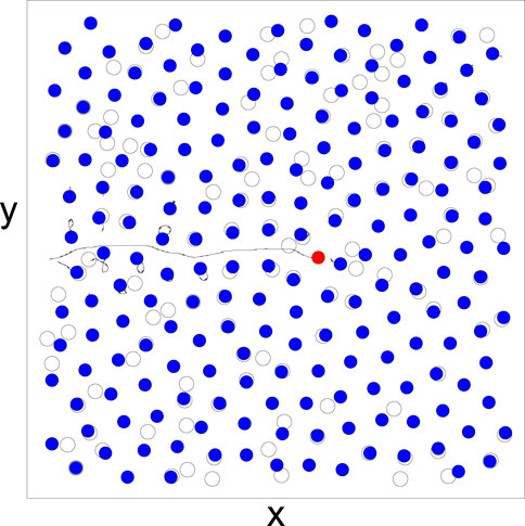
FIGURE 1. An image of a subsection of the system in which a single skyrmion (red) is driven through an assembly of other skyrmions (blue) in the presence of quenched disorder, generated by randomly placed nonoverlapping local trapping sites (open circles). Black lines indicate the skyrmion trajectories. The driven skyrmion generates motion of the surrounding skyrmions as it passes through the system.
In Figure 2A, we plot the average velocity parallel to the drive, ⟨V‖⟩, versus FD for the system in Figure 1 with ns = 0.5, αm = 0.1, and αd = 0.995. Here, we employ the constraint
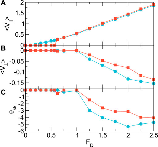
FIGURE 2. (A) The velocity ⟨V‖⟩ parallel to the driving direction versus drive FD for the system in Figure 1 with ns = 0.5, αm = 0.1, αd = 0.995, and
In Figure 3, we plot the depinning force Fc versus skyrmion density ns for the systems in Figure 2 with and without pinning. In the absence of pinning, Fc starts from zero and increases monotonically with increasing ns as it becomes more difficult to push the skyrmion through the system. When pinning is present, at low ns, the driven skyrmion interacts only with the pinning sites, giving Fc = Fp; however, once the density increases enough for the driven skyrmion to interact with both pinning sites and other skyrmions, Fc sharply increases and reaches a maximum value near ns = 0.5. The maximum depinning force
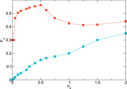
FIGURE 3. The depinning force Fc versus skyrmion density ns for the systems in Figure 2 with αm = 0.1, αd = 0.995, and
In Figure 4A, we plot the time series of the parallel velocity V‖ for the system in Figure 2 at ns = 0.5 with no quenched disorder for FD = 0.3, just above depinning. A series of short-period oscillations appear which correspond to elastic interactions in which the driven skyrmion moves past a background skyrmion without generating plastic displacements of the background skyrmions. There are also infrequent larger signals in the form of sharp velocity dips that are correlated with the creation of a plastic distortion or exchange of neighbors among the background skyrmions due to the passage of the driven skyrmion. In Figure 4B, we show the time series of V‖ for the system with quenched disorder at FD = 0.625, just above the depinning threshold. Here, the motion is much more disordered, with strong short-time velocity oscillations. These are produced by the motion of the driven skyrmion over the background pinning sites. The overall structure of the background skyrmions is disordered, destroying the periodic component of motion found in the unpinned system.
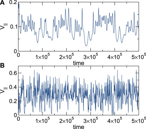
FIGURE 4. The time series of the velocity V‖ parallel to the drive for the system in Figure 2 with ns = 0.5, αm = 0.1, αd = 0.995, and
We next examine the power spectra S(ω) of time series such as those shown in Figure 4 for different drives for the systems in Figure 2. Generically, power spectra can take several forms including 1/f α, where α = 0 indicates white noise with little or no correlation, α = 2 is Brownian noise, and α = 1 or pink noise can appear when large-scale collective events occur [47]. Noise signatures that are periodic produce narrowband signals with peaks at specific frequencies. It is also possible to have combinations in which the signal is periodic on one time scale but has random fluctuations on longer time scales. For assemblies of particles under an applied drive that exhibit plastic depinning, the power spectrum is typically of 1/f α type with α ranging from α = 1.3 to α = 2.0. A single particle moving over an uncorrelated random landscape typically shows a white noise spectrum, while motion over a periodic substrate produces narrowband noise features [21].
In Figure 5A, we plot S(ω) for the disorder-free system with np = 0 from Figure 2 at FD = 0.2, just above the depinning threshold. At low frequencies, we find a series of oscillations or a narrowband noise feature. These periodic velocity oscillations correspond to the driven skyrmion speeding up and slowing down as it moves through the roughly triangular lattice formed by the surrounding skyrmions. The driven skyrmion occasionally generates dislocations or topological defects in the background lattice, so the motion is not strictly periodic but exhibits a combination of periodic motion with intermittent large bursts. This intermittent signal is what gives the spectrum an overall 1/f α shape, as indicated by the red line which is a fit with α = 1.25. The noise power drops at higher frequencies, which are correlated with the small rotations caused by the Magnus force as the driven skyrmion generates plastic events. In Figure 5B, we show the velocity spectrum in the disorder-free sample at FD = 0.3 for the time series illustrated in Figure 4A. The overall shape of the spectrum is similar to that found at FD = 0.2 in Figure 5A, but the low-frequency oscillations are reduced since more plastic events are occurring in the background skyrmion lattice. A power-law fit with α = 0.85 appears as a straight line in Figure 5B. In overdamped driven systems with quenched disorder, the power-law exponent is observed to decrease with increasing drive, until it reaches a white noise state with α = 0, and a narrowband noise signature appears at high drives [18,19,21]. In Figure 5C at FD = 1.0, the response at lower frequencies has become a white noise spectrum with α = 0, while at slightly higher frequencies, there is the beginning of a narrowband noise peak. At FD = 1.5 in Figure 5D, strong narrowband peaks appear in the spectrum. The narrowband noise arises once the driven skyrmion is moving fast enough that it no longer has time to generate dislocations or other defects in the surrounding lattice, making the system appear more like a single particle moving over a triangular lattice and creating few to no distortions. For high drives, the same narrowband noise signal appears, but the peaks shift to higher frequencies as the driven skyrmion moves faster. The narrowband noise frequencies are related to the time t = a/v between collisions with other skyrmions, where a is the skyrmion lattice constant, and v is the average skyrmion velocity at a specific drive, giving ω = v/a. This implies that for higher FD, the narrowband noise peak will shift to higher frequencies, consistent with our observations. Similar periodic signals observed for moving superconducting vortices are described in terms of a washboard frequency which is also proportional to v/a, and which appears when the vortices form an ordered lattice [54,19]. In well-ordered lattices, the narrowband noise peaks are sharp, while when the lattice is disordered but large-scale plastic deformations do not occur, narrowband noise peaks are still present but become broadened. When the quenched disorder is strong enough to generate large plastic events in which groups of skyrmions move along with the driven probe skyrmion, the noise becomes white and adopts a ω−α form.
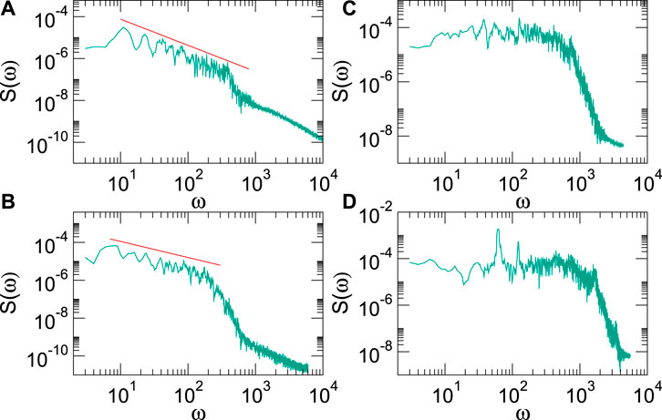
FIGURE 5. (A) The power spectra S(ω) for the system in Figure 2 with ns = 0.5, αm = 0.1, αd = 0.995,
In Figure 6A, we plot S(ω) for the pinned system with np = 0.3 and Fp = 0.3 from Figure 4B at FD = 0.625, just above depinning. At low frequencies, the power spectrum is nearly white with α = 0, while the noise power drops as 1/f 2 at high frequencies. Unlike the pin-free system, strong low-frequency oscillations are absent because the lattice structure of the surrounding skyrmions is disordered by the pinning sites. We find no 1/f noise, in part due to the reduced mobility of the skyrmions trapped at pinning sites, which reduces the amount of plastic events which can occur. In the absence of pinning, the driven skyrmion can more readily create exchanges of neighbors in the background skyrmions, generating longer range distortions in the system and creating more correlated fluctuations in the driven skyrmion velocity. In Figure 6B, we plot S(ω) for the same system at a higher drive of FD = 1.5, where again similar white noise appears at low frequencies, while the transition from white noise to 1/f 2 noise has shifted to a higher frequency. Unlike the disorder-free sample, here, we find no narrowband signal since the surrounding skyrmions are trapped in disordered positions by the pinning. The addition of quenched disorder might be expected to increase the appearance of 1/f noise due to the greater disorder in the system; however, in this case, the quenched disorder suppresses the plastic events responsible for the broadband noise signature. In a globally driven assembly of particles, the drive itself can induce plastic events [21]. This implies that the fluctuations of a single probe particle driven over quenched disorder are expected to differ significantly from the noise signatures found in bulk-driven systems. The spectra in Figure 6 have a shape called Lorentzian,
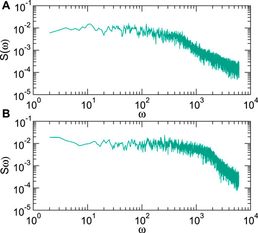
FIGURE 6. The power spectra S(ω) for the system in Figure 2 with quenched disorder at ns = 0.5, αm = 0.1, αd = 0.995,
We next consider the influence of the Magnus force on the noise fluctuations of the driven skyrmion. In Figure 7A, we plot the time series of V‖ at FD = 1.0 for a system without quenched disorder in the completely overdamped limit of αm = 0.0 and αd = 1.0. For the equivalent drive in a sample with αm = 0.1 and αd = 0.995, Figure 5C shows that white noise is present; however, for the overdamped system, Figure 7B indicates that a strong narrowband noise signal appears. In the image in Figure 8A, the driven skyrmion moves through the lattice of other skyrmions without creating plastic distortions. In general, we find that in the overdamped limit and in the absence of pinning, a strong narrowband noise signal appears as the driven skyrmion moves elastically through an ordered skyrmion lattice, as shown in the linear-linear plot of S(ω) in Figure 7B. In Figure 7C, we plot the time series of V‖ for the same system in the Magnus-dominated regime with αm/αd = 9.95 and
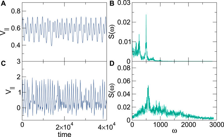
FIGURE 7. (A) The time series of the velocity V‖ parallel to the drive at ns = 0.5 and FD = 1.0 for an overdamped system with αm/αd = 0 and no quenched disorder. (B) The corresponding power spectrum S(ω) contains narrowband peaks. (C) The time series for the same system but with αm/αd = 9.95, where the fluctuations are enhanced. (D) The corresponding power spectrum S(ω) has a reduced amount of narrowband noise.
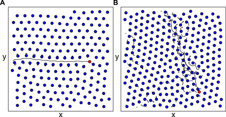
FIGURE 8. An image of a subsection of the system showing the driven skyrmion (red), background skyrmions (blue), and skyrmion trajectories (black lines) for the samples from Figure 7 with ns = 0.5 at FD = 1.0. (A) For the overdamped system with αm/αd = 0 from Figures 7A,B, the background skyrmions experience elastic distortions, but there are no plastic events. (B) For the Magnus-dominated system with αm/αd = 9.95 from Figures 7C,D, the driven skyrmion moves at an angle due to the increased Magnus force, creating significant distortions in the background skyrmion lattice.
We next consider the effect of the pinning strength on the dynamics. In Figure 9A, we plot the time series of V‖ for a system with αm/αd = 0.1, ns = 0.5, np = 0.3, Fp = 2.0, and FD = 1.6. Here, the driven skyrmion experiences a combination of sliding and nearly pinned motion, where at certain points, the skyrmion is temporarily trapped by a combination of the pinning and the skyrmion-skyrmion interactions. As the surrounding skyrmions relax, the driven skyrmion can jump out of the pinning site where it has become trapped, leading to another pulse of motion. This stick-slip or telegraph-type motion only occurs just above the critical driving force when the pinning force is sufficiently strong, while for higher drives, the motion becomes continuous. In Figure 9B, we show the time series of V‖ for the same system at αm/αd = 9.95, where the stick-slip or telegraph motion is lost. We note that the value of ⟨V‖⟩ in the Magnus-dominated αm/αd = 9.95 system is smaller than that found in the overdamped αm/αd = 0.1 system since the increasing Magnus force rotates more of the velocity into the direction perpendicular to the drive; however, a similar continuous flow is observed both parallel and perpendicular to the drive in the Magnus-dominated system. The loss of the stick-slip motion is due to the increasing spiraling motion of both the driven and background skyrmions. In Figure 9C, we plot the power spectra corresponding to the time series in Figures 9A,B. The stick-slip motion of the αm/αd = 0.1 system produces a 1/f α signature in S(ω) with α = 1.3. For the αm/αd = 9.95 sample, S(ω) is much flatter, indicating reduced correlations in the fluctuations, and also has increased noise power at high frequencies. The enhanced high-frequency noise results from the fast spiraling motion of both the driven and the background skyrmions when they are inside pinning sites. The detection of enhanced high-frequency noise could thus provide an indication that strong pinning effects or strong Magnus forces are present. In Figure 9D, we plot the distribution P(V‖) of instantaneous velocity for the samples in Figures 9A,B. When αm/αd = 0.1, P(V‖) is bimodal with a large peak near V‖ = 0 and a smaller peak near V = 1.6, corresponding to the value of the driving force. There is no gap of zero weight in P(V‖) separating these two peaks. When αm/αd = 9.95, P(V‖) has only a single peak at intermediate velocities. Additionally, there is significant weight at negative velocities, which were not present in the strongly damped sample. The negative velocities arise when the skyrmions move in circular orbits due to the Magnus force and spend a portion of the orbit moving in the direction opposite to the driving force.
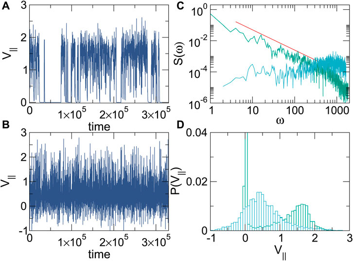
FIGURE 9. Samples with ns = 0.5, np = 0.3, Fp = 2.0, and FD = 1.6. (A) Time series of V‖ for a system with αm/αd = 0.1. (B) Time series of V‖ for a system with αm/αd = 9.95. (C) The power spectra S(ω) for the αm/αd = 0.1 system (green) showing a power-law fit to 1/fα with α = 1.3 (red line), and S(ω) for the αm/αd = 9.95 system (blue). (D) Distribution P(V‖) of velocities in the direction parallel to the drive for the αm/αd = 0.1 system (green), where a bimodal shape appears, and for the αm/αd = 9.95 system (blue), where the distribution is unimodal.
In Figure 10A, we plot the average velocity ⟨V‖⟩ versus pinning strength Fp for the system in Figure 9A with αm/αd = 0.1, ns = 0.5, and np = 0.3 at FD = 2.0, 1.75, 1.5, 1.25, 1.0, 0.75, and 0.5. The pinning force at which ⟨V‖⟩ reaches zero, indicating the formation of a pinned state, increases as FD increases. Generally, there is also a range of low Fp over which ⟨V‖⟩ increases with increasing Fp. This is due to a reduction in the drag on the driven skyrmion as the background skyrmions become more firmly trapped in the pinning sites, similar to what was illustrated in Figure 2. Stick-slip motion appears in the regime where there is a sharp downturn in ⟨V‖⟩ and is associated with a bimodal velocity distribution of the type shown in Figure 9D. A plot of ⟨V‖⟩ versus Fp for the αm/αd = 9.95 system (not shown) reveals a similar trend, except that the pinning transitions shift to larger values of Fp. Using the features in Figure 10A combined with the velocity distributions, we construct a dynamic phase diagram for the αm/αd = 0.1 system as a function of Fp versus FD, illustrated in Figure 10B. We observe continuous flow, stick-slip motion, and pinned regimes, with stick-slip motion occurring only when Fp > 0.75. In general, for increasing Magnus force, the window of stick-slip motion decreases in size.
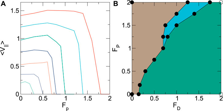
FIGURE 10. (A) ⟨V‖⟩ versus pinning strength Fp for the system in Figure 9A with ns = 0.5, np = 0.3, and αm/αd = 0.1 at FD = 2.0, 1.75, 1.5, 1.25, 1.0, 0.7, and 0.5, from top to bottom. (B) Dynamic phase diagram for the same system as a function of Fp versus FD. Green: continuous flow regime; blue: stick-slip motion; brown: pinned.
In Figure 11A, we plot ⟨V‖⟩ versus the skyrmion density ns for the system in Figure 9A with Fp = 1.6, np = 0.3, and αm/αd = 0.1 at FD = 1.4, 1.6, 1.8, 2.0, 2.2, 2.4, and 2.6. At FD = 1.4, the system is pinned when ns ≤ 1.0. For this skyrmion density, all of the skyrmions can be trapped at pinning sites and are therefore unable to move since FD < Fp. As ns increases, all of the pinning sites become filled and interstitial skyrmions appear which are pinned only by repulsion from other skyrmions directly located at pinning sites. The strength of this interstitial pinning is determined by the elastic properties of the skyrmion lattice, and for these densities, it is weaker than Fp. When FD > Fp, flow can occur even for low ns, where the driven skyrmion interacts with the pinning sites but has few collisions with background skyrmions. In the limit ns = 0 where only the driven skyrmion is present, the system is always flowing whenever FD/Fp > 1.0. For the FD = 2.2 curve, the system is flowing up to ns = 0.2, and then, a pinned region appears for 0.2 < ns < 0.5. At this range of skyrmion densities, even though FD > Fp, the driven skyrmion experiences a combination of direct pinning from the pinning sites it encounters plus interstitial pinning by the nearby directly pinned skyrmions, giving an additive effect which causes the apparent pinning strength to be larger than FD. For ns > 0.5, all the pinning sites start to become occupied, and the driven skyrmion experiences only the weaker interstitial pinning without becoming trapped directly by any pinning sites. At small FD, it is possible for the driven skyrmion to become trapped by a pinning site that is already occupied by a background skyrmion, creating a doubly occupied pinning site, which is why the value of ns below which the driven skyrmion can begin to move again shifts to larger ns with decreasing FD. The reentrant pinning effect illustrated in Figure 11A arises from the combination of the direct and interstitial pinning mechanisms. In Figure 11B, we construct a dynamic phase diagram as a function of ns/np versus FD for the system in Figure 11A showing the pinned and flowing phases. Reentrant pinning occurs over the range FD = Fp = 1.6 to slightly above FD = 2.2. The reentrant pinned phase reaches its maximum extent near ns/np = 1.0, a density at which the number of directly pinned skyrmions attains its maximum value while the number of interstitially pinned skyrmions is still nearly zero.
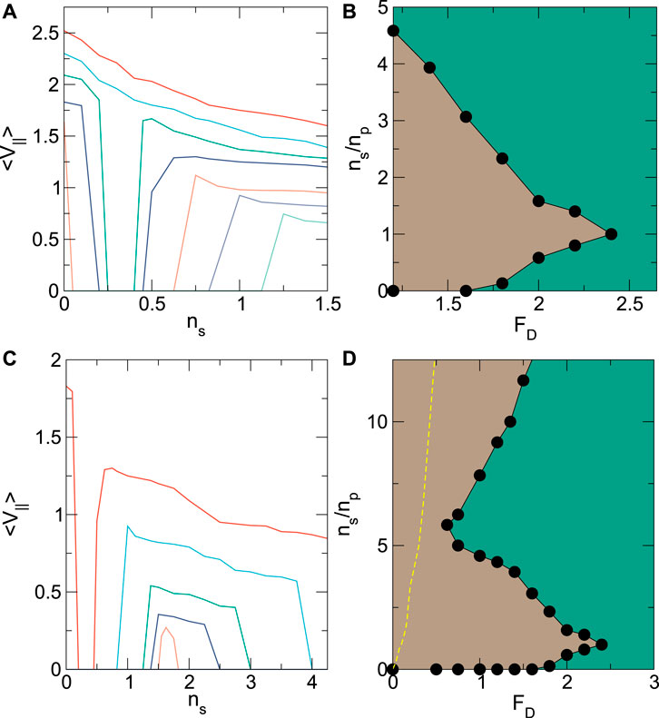
FIGURE 11. (A) ⟨V‖⟩ versus skyrmion density ns for the system in Figure 9A with np = 0.3, Fp = 1.6, and αm/αd = 0.1 at FD = 1.4, 1.6, 1.8, 2.0, 2.2, 2.4, and 2.6, from bottom to top. (B) Dynamic phase diagram for the same system as a function of ns/np versus FD. Green: continuous flow regime; brown: pinned. (C) ⟨V‖⟩ versus ns for the system in panel (A) plotted up to a maximum value of ns = 4.0 for FD = 0.75, 1.0, 1.2, 1.6, and 2.0, from bottom to top. Note that for FD = 0.5, ⟨V‖⟩ = 0 over this entire range of ns. (D) Dynamic phase diagram for the same system as a function of ns/np versus FD. Green: continuous flow regime; brown: pinned. The yellow dashed line indicates the location of the depinning threshold in systems with no quenched disorder.
For higher values of ns/np, another pinned phase arises at low values of FD that is produced by the skyrmion-skyrmion interactions. In Figure 11D, we plot ⟨V‖⟩ versus ns up to ns = 4.0 for FD = 0.5, 0.75, 1.0, 1.2, 1.6, and 2.0 in the same system from Figure 11. Note that for FD = 0.5, ⟨V‖⟩ = 0 over the entire range of ns. At higher ns, ⟨V‖⟩ drops to zero again as the system reaches a pinned state. This second pinned phase is produced by the increase in the elastic skyrmion-skyrmion interaction energies at the higher densities. In the absence of quenched disorder, the skyrmion-skyrmion interactions are the only mechanism by which the driven skyrmion can be pinned, and there is a threshold for motion which increases monotonically with increasing ns. When quenched disorder is introduced, the threshold becomes both nonmonotonic and reentrant. For increasing FD in Figure 11C, the elastic energy-induced pinning transition shifts to higher ns. In Figure 11D, we show a dynamic phase diagram as a function of ns/np versus FD for the system in Figure 11C indicating the locations of the pinned and flowing phases. For ns/np < 2.0, the reentrant pinned state produced by a combination of direct and interstitial pinning reaches its maximum extent. As ns/np increases, the pinned state reaches a minimum width near ns/np = 5.5, above which the pinned region begins to grow again. The yellow dashed line is the depinning threshold in the absence of quenched disorder, which always falls below the depinning transition of samples with quenched disorder. The increase in the depinning threshold due to the addition of pinning occurs even when the number of skyrmions is significantly larger than the number of pinning sites since even a relatively small number of pins can prevent plastic distortions of the background skyrmions, raising the barrier for motion of the driven skyrmion.
In the phase diagram of Figure 11B and Figure 11D, for drives just above the pinned phase, there is a small window of stick-slip motion (not shown) which is more prominent for lower values of ns/np. In addition, within the flowing phase, there is another critical drive above which there is an onset of transverse motion, giving a finite Hall angle. This line has a shape similar to that of the depinning curve but falls at higher values of FD.
In this work, we considered a point-like model for skyrmions. In real skyrmion systems, there is an effective skyrmion size that can change with field or exhibit internal modes. It may be possible that at low fields, the particle picture works well, while at higher fields, the skyrmions will start to change shape. Micromagnetic simulations could capture situations in which the individual spin degrees of freedom become important, such as when the skyrmions become deformed when interacting with a pinning site. Skyrmion deformations could also produce changes in the noise fluctuations or spectral signatures since the internal modes of the skyrmions can be associated with distinct frequencies. A micromagnetic model could also treat systems in which different types of skyrmions are present, such as ferromagnetic skyrmions versus antiferromagnetic skyrmions or antiskyrmions. It would be interesting to study how the effective drag on the driven skyrmion would change in this case. As previously demonstrated experimentally, the system we consider could be realized by dragging an individual skyrmion with a local atomic force microscope or magnetic force microscope tip. There have also been proposals to manipulate individual skyrmions with optical traps. Such local probes would allow the fluctuations and velocity noise of the individual driven skyrmion to be measured. Another method for achieving relative plastic motion of skyrmions on the scale of the skyrmion lattice constant would be to use a sample containing skyrmions of different sizes or different species in which one size or species couples more strongly to the external drive and moves more rapidly than the other sizes or species of skyrmions. In this work, we focus on the strong pinning regime in which interactions with the substrate produce plastic distortions or tearing of the skyrmion lattice. For weaker pinning, an elastic regime can appear in which plastic deformations do not occur, and a single driven skyrmion can drag the entire skyrmion assembly along with it. There could also be a finite range for the elastic interaction, with the driven skyrmion dragging a large elastically stable chunk of skyrmions along with it, and with plastic deformations occurring only on much larger length scales [21]. This would suggest the existence of an elastic to plastic transition that could be detected by varying the driving velocity or other parameters. It would also be interesting to consider driving an individual three-dimensional skyrmion line. Here, only the top portion of the skyrmion might respond to the driving force, while the lower portion of the line is passively dragged by the skyrmion line tension. This type of effect has been studied for three-dimensional superconducting vortex lines.
Another question regards the distinction between pinning-dominated pinned states, where direct pinning is responsible for producing the pinning, and interstitial-dominated or jammed pinned states, where the pinning of the driven skyrmion arises from elastic interactions with directly pinned skyrmions. The fluctuations in the jammed state generally show that there is a greater tendency for large-scale plastic events to occur, leading to a larger amount of low-frequency noise compared to the pinning-dominated state. In work on superconducting vortices with quenched disorder, the presence of pinned, jammed, and clogged phases could be deduced by measuring memory effects [55]. For the single driven skyrmion, memory could be tested by reversing the driving direction. For strong pinning, the trajectory under reversed drive should mirror that of the forward drive, indicating a memory effect, whereas in samples with strong plastic distortions, the trajectory for forward and reversed drive will differ due to the appearance of plastic distortions in the background skyrmions.
We have examined the fluctuations and pinning effects for individually driven skyrmions moving through an assembly of other skyrmions and quenched disorder. We find that in the absence of quenched disorder, there is a depinning force that increases monotonically with increasing skyrmion density. When quenched disorder is introduced, the driven skyrmion experiences a combination of pinning and drag effects from both the pinning sites and the background skyrmions. Both with and without quenched disorder, there is a second, higher driving threshold for the onset of motion transverse to the drive and the appearance of a finite skyrmion Hall angle. For higher drives, the addition of quenched disorder actually increases the velocity of the driven skyrmion since the pinning sites help prevent the background skyrmions from being dragged along by the driven skyrmion. Near depinning, in the absence of quenched disorder, the velocity fluctuations show a combination of periodic oscillations from the elasticity of the ordered background skyrmion lattice along with stronger jumps associated with plastic distortions of the background skyrmions. This produces a velocity power spectrum that has narrowband noise peaks superimposed on a 1/f α shape with α = 1.2. As the drive increases, the spectrum becomes white, and for very high drives, a strong narrowband signature emerges once the driven skyrmion is moving too rapidly to generate plastic distortions in the background skyrmions. The addition of quenched disorder reduces the frequency of plastic events, giving a white noise spectrum. In the absence of disorder, a damping-dominated system generally shows strong narrowband noise fluctuations as the driven skyrmion moves along one-dimensional paths in the background skyrmion lattice, whereas in the Magnus-dominated limit, the driven skyrmion moves at an angle through the lattice, generating dislocations and reducing the strength of the narrowband signature. When the disorder is strong, the driven skyrmion can undergo stick-slip motion due to a combination of being trapped at pinning sites and interacting elastically with the background skyrmions, which produces a bimodal velocity distribution along with 1/f α noise. For systems with quenched disorder, the depinning threshold is highly nonmonotonic as a function of the skyrmion density, passing through both peaks and minima. This is due to a competition between two different pinning effects. The depinning threshold drops when the number of skyrmions becomes larger than the number of pinning sites since the driven skyrmion must be pinned through interstitial interactions with directly pinned skyrmions instead of sitting in a pinning site directly; however, at higher densities, the increasing strength of the elastic interactions between the skyrmions causes the depinning threshold to rise again with increasing density. At low densities, the system can be viewed as being in a pinning-dominated regime, while at higher densities, it is in an interstitial-dominated or jamming regime. Beyond skyrmions, our results should be relevant to fluctuations in other particle-based systems such as individually dragged vortices in type-II superconductors.
The original contributions presented in the study are included in the article/Supplementary Material, and further inquiries can be directed to the corresponding author.
All authors listed have made a substantial, direct, and intellectual contribution to the work and approved it for publication.
We gratefully acknowledge the support of the US Department of Energy through the LANL/LDRD program for this work. This work was supported by the US Department of Energy through the Los Alamos National Laboratory. The Los Alamos National Laboratory is operated by Triad National Security, LLC, for the National Nuclear Security Administration of the US Department of Energy (Contract No. 892333218NCA000001).
The authors declare that the research was conducted in the absence of any commercial or financial relationships that could be construed as a potential conflict of interest.
All claims expressed in this article are solely those of the authors and do not necessarily represent those of their affiliated organizations or those of the publisher, the editors, and the reviewers. Any product that may be evaluated in this article, or claim that may be made by its manufacturer, is not guaranteed or endorsed by the publisher.
1. Mühlbauer S, Binz B, Jonietz F, Pfleiderer C, Rosch A, Neubauer A, et al. Skyrmion Lattice in a Chiral Magnet. Science (2009) 323:915–9. doi:10.1126/science.1166767
2. Yu XZ, Onose Y, Kanazawa N, Park JH, Han JH, Matsui Y, et al. Real-space Observation of a Two-Dimensional Skyrmion crystal. Nature (2010) 465:901–4. doi:10.1038/nature09124
3. Nagaosa N, Tokura Y. Topological Properties and Dynamics of Magnetic Skyrmions. Nat Nanotech (2013) 8:899–911. doi:10.1038/NNANO.2013.243
4. Iwasaki J, Mochizuki M, Nagaosa N. Universal Current-Velocity Relation of Skyrmion Motion in Chiral Magnets. Nat Commun (2013) 4:1463. doi:10.1038/ncomms2442
5. Schulz T, Ritz R, Bauer A, Halder M, Wagner M, Franz C, et al. Emergent Electrodynamics of Skyrmions in a Chiral Magnet. Nat Phys (2012) 8:301–4. doi:10.1038/NPHYS2231
6. Woo S, Litzius K, Krüger B, Im M-Y, Caretta L, Richter K, et al. Observation of Room-Temperature Magnetic Skyrmions and Their Current-Driven Dynamics in Ultrathin Metallic Ferromagnets. Nat Mater (2016) 15:501–6. doi:10.1038/nmat4593
7. Reichhardt C, Reichhardt CJO, Milosevic MV. Statics and Dynamics of Skyrmions Interacting with Pinning: a Review. arXiv e-prints (2021). arXiv:2102.10464
8. Everschor-Sitte K, Sitte M. Real-space Berry Phases: Skyrmion Soccer (Invited). J Appl Phys (2014) 115:172602. doi:10.1063/1.4870695
9. Reichhardt C, Ray D, Reichhardt CJO. Collective Transport Properties of Driven Skyrmions with Random Disorder. Phys Rev Lett (2015) 114:217202. doi:10.1103/PhysRevLett.114.217202
10. Jiang W, Zhang X, Yu G, Zhang W, Wang X, Benjamin Jungfleisch M, et al. Direct Observation of the Skyrmion Hall Effect. Nat Phys (2017) 13:162–9. doi:10.1038/NPHYS3883
11. Litzius K, Lemesh I, Krüger B, Bassirian P, Caretta L, Richter K, et al. Skyrmion Hall Effect Revealed by Direct Time-Resolved X-ray Microscopy. Nat Phys (2017) 13:170–5. doi:10.1038/NPHYS4000
12. Reichhardt C, Reichhardt CJO. Thermal Creep and the Skyrmion Hall Angle in Driven Skyrmion Crystals. J Phys Condens Matter (2019) 31:07LT01. doi:10.1088/1361-648X/aaefd7
13. Juge R, Je S-G, Chaves Dd. S, Buda-Prejbeanu LD, Peña Garcia J, Nath J, et al. Current-driven Skyrmion Dynamics and Drive-dependent Skyrmion Hall Effect in an Ultrathin Film. Phys Rev Appl (2019) 12:044007. doi:10.1103/physrevapplied.12.044007
14. Zeissler K, Finizio S, Barton C, Huxtable AJ, Massey J, Raabe J, et al. Diameter-independent Skyrmion Hall Angle Observed in Chiral Magnetic Multilayers. Nat Commun (2020) 11:428. doi:10.1038/s41467-019-14232-9
15. Díaz SA, Reichhardt CJO, Arovas DP, Saxena A, Reichhardt C. Fluctuations and Noise Signatures of Driven Magnetic Skyrmions. Phys Rev B (2017) 96:085106. doi:10.1103/PhysRevB.96.085106
16. Sato T, Koshibae W, Kikkawa A, Yokouchi T, Oike H, Taguchi Y, et al. Slow Steady Flow of a Skyrmion Lattice in a Confined Geometry Probed by Narrow-Band Resistance Noise. Phys Rev B (2019) 100:094410. doi:10.1103/physrevb.100.094410
17. Sato T, Kikkawa A, Taguchi Y, Tokura Y, Kagawa F. Mode Locking Phenomena of the Current-Induced Skyrmion-Lattice Motion in Microfabricated MnSi. Phys Rev B (2020) 102:180411. doi:10.1103/PhysRevB.102.180411
18. Marley AC, Higgins MJ, Bhattacharya S. Flux Flow Noise and Dynamical Transitions in a Flux Line Lattice. Phys Rev Lett (1995) 74:3029–32. doi:10.1103/physrevlett.74.3029
19. Olson CJ, Reichhardt C, Nori F. Nonequilibrium Dynamic Phase Diagram for Vortex Lattices. Phys Rev Lett (1998) 81:3757–60. doi:10.1103/physrevlett.81.3757
20. Grüner G. The Dynamics of Charge-Density Waves. Rev Mod Phys (1988) 60:1129–81. doi:10.1103/RevModPhys.60.1129
21. Reichhardt C, Olson Reichhardt CJ. Depinning and Nonequilibrium Dynamic Phases of Particle Assemblies Driven over Random and Ordered Substrates: a Review. Rep Prog Phys (2017) 80:026501. doi:10.1088/1361-6633/80/2/026501
22. Fert A, Reyren N, Cros V. Magnetic Skyrmions: Advances in Physics and Potential Applications. Nat Rev Mater (2017) 2:17031. doi:10.1038/natrevmats.2017.31
23. Luo S, You L. Skyrmion Devices for Memory and Logic Applications. APL Mater (2021) 9:050901. doi:10.1063/5.0042917
24. Hastings MB, Olson Reichhardt CJ, Reichhardt C. Depinning by Fracture in a Glassy Background. Phys Rev Lett (2003) 90:098302. doi:10.1103/PhysRevLett.90.098302
25. Habdas P, Schaar D, Levitt AC, Weeks ER. Forced Motion of a Probe Particle Near the Colloidal Glass Transition. Europhys Lett (2004) 67:477–83. doi:10.1209/epl/i2004-10075-y
26. Zia RN. Active and Passive Microrheology: Theory and Simulation. Annu Rev Fluid Mech (2018) 50:371–405. doi:10.1146/annurev-fluid-122316-044514
27. Dullens RPA, Bechinger C. Shear Thinning and Local Melting of Colloidal Crystals. Phys Rev Lett (2011) 107:138301. doi:10.1103/PhysRevLett.107.138301
28. Gazuz I, Puertas AM, Voigtmann T, Fuchs M. Active and Nonlinear Microrheology in Dense Colloidal Suspensions. Phys Rev Lett (2009) 102:248302. doi:10.1103/PhysRevLett.102.248302
29. Candelier R, Dauchot O. Journey of an Intruder through the Fluidization and Jamming Transitions of a Dense Granular media. Phys Rev E (2010) 81:011304. doi:10.1103/PhysRevE.81.011304
30. Olson Reichhardt CJ, Reichhardt C. Fluctuations, Jamming, and Yielding for a Driven Probe Particle in Disordered Disk Assemblies. Phys Rev E (2010) 82:051306. doi:10.1103/PhysRevE.82.051306
31. Olson Reichhardt CJ, Reichhardt C. Viscous Decoupling Transitions for Individually Dragged Particles in Systems with Quenched Disorder. Phys Rev E (2008) 78:011402. doi:10.1103/PhysRevE.78.011402
32. Gruber M, Puertas AM, Fuchs M. Critical Force in Active Microrheology. Phys Rev E (2020) 101:012612. doi:10.1103/PhysRevE.101.012612
33. Straver EWJ, Hoffman JE, Auslaender OM, Rugar D, Moler KA. Controlled Manipulation of Individual Vortices in a Superconductor. Appl Phys Lett (2008) 93:172514. doi:10.1063/1.3000963
34. Auslaender OM, Luan L, Straver EWJ, Hoffman JE, Koshnick NC, Zeldov E, et al. Mechanics of Individual Isolated Vortices in a Cuprate Superconductor. Nat Phys (2009) 5:35–9. doi:10.1038/NPHYS1127
35. Veshchunov IS, Magrini W, Mironov SV, Godin AG, Trebbia J-B, Buzdin AI, et al. Optical Manipulation of Single Flux Quanta. Nat Commun (2016) 7:12801. doi:10.1038/ncomms12801
36. Kremen A, Wissberg S, Haham N, Persky E, Frenkel Y, Kalisky B. Mechanical Control of Individual Superconducting Vortices. Nano Lett (2016) 16:1626–30. doi:10.1021/acs.nanolett.5b04444
37. Ma X, Reichhardt CJO, Reichhardt C. Manipulation of Individual Superconducting Vortices and Stick-Slip Motion in Periodic Pinning Arrays. Phys Rev B (2018) 97:214521. doi:10.1103/PhysRevB.97.214521
38. Illien P, Bénichou O, Oshanin G, Sarracino A, Voituriez R. Nonequilibrium Fluctuations and Enhanced Diffusion of a Driven Particle in a Dense Environment. Phys Rev Lett (2018) 120:200606. doi:10.1103/PhysRevLett.120.200606
39. Hanneken C, Kubetzka A, von Bergmann K, Wiesendanger R. Pinning and Movement of Individual Nanoscale Magnetic Skyrmions via Defects. New J Phys (2016) 18:055009. doi:10.1088/1367-2630/18/5/055009
40. Holl C, Knol M, Pratzer M, Chico J, Fernandes IL, Lounis S, et al. Probing the Pinning Strength of Magnetic Vortex Cores with Sub-nanometer Resolution. Nat Commun (2020) 11:2833. doi:10.1038/s41467-020-16701-y
41. Wang X-G, Chotorlishvili L, Dugaev VK, Ernst A, Maznichenko IV, Arnold N, et al. The Optical Tweezer of Skyrmions. Npj Comput Mater (2020) 6:140. doi:10.1038/s41524-020-00402-7
42. Reichhardt C, Reichhardt CJO. Dynamics and Nonmonotonic Drag for Individually Driven Skyrmions. Phys Rev B (2021) 104:064441. doi:10.1103/physrevb.104.064441
43. Reichhardt C, Reichhardt CJO. Aspects of Jamming in Two-Dimensional Athermal Frictionless Systems. Soft Matter (2014) 10:2932–44. doi:10.1039/c3sm53154f
44. Thiele AA. Steady-state Motion of Magnetic Domains. Phys Rev Lett (1973) 30:230–3. doi:10.1103/PhysRevLett.30.230
45. Lin S-Z, Reichhardt C, Batista CD, Saxena A. Particle Model for Skyrmions in Metallic Chiral Magnets: Dynamics, Pinning, and Creep. Phys Rev B (2013) 87:214419. doi:10.1103/PhysRevB.87.214419
46. Brown BL, Täuber UC, Pleimling M. Effect of the Magnus Force on Skyrmion Relaxation Dynamics. Phys Rev B (2018) 97:020405. doi:10.1103/physrevb.97.020405
47. Weissman MB. 1fnoise and Other Slow, Nonexponential Kinetics in Condensed Matter. Rev Mod Phys (1988) 60:537–71. doi:10.1103/revmodphys.60.537
48. Bullard TJ, Das J, Daquila GL, Täuber UC. Vortex Washboard Voltage Noise in Type-II Superconductors. Eur Phys J B (2008) 65:469–84. doi:10.1140/epjb/e2008-00358-7
49. Reichhardt C, Olson Reichhardt CJ. Noise Fluctuations and Drive Dependence of the Skyrmion Hall Effect in Disordered Systems. New J Phys (2016) 18:095005. doi:10.1088/1367-2630/18/9/095005
50. Müller J, Rosch A. Capturing of a Magnetic Skyrmion with a Hole. Phys Rev B (2015) 91:054410. doi:10.1103/PhysRevB.91.054410
51. Reichhardt C, Ray D, Reichhardt CJO. Quantized Transport for a Skyrmion Moving on a Two-Dimensional Periodic Substrate. Phys Rev B (2015) 91:104426. doi:10.1103/PhysRevB.91.104426
52. Reichhardt C, Reichhardt CJO. Thermal Creep and the Skyrmion Hall Angle in Driven Skyrmion Crystals. J Phys Condens Matter (2018) 31:07LT01. doi:10.1088/1361-648X/aaefd7
53. Fernandes IL, Chico J, Lounis S. Impurity-dependent Gyrotropic Motion, Deflection and Pinning of Current-Driven Ultrasmall Skyrmions in Pdfe/ir(111) Surface. J Phys Condens Matter (2020) 32:425802. doi:10.1088/1361-648X/ab9cf0
54. Harris JM, Ong NP, Gagnon R, Taillefer L. Washboard Frequency of the Moving Vortex Lattice in YBa2Cu3O6.93 Detected by Ac-Dc Interference. Phys Rev Lett (1995) 74:3684–7. doi:10.1103/PhysRevLett.74.3684
Keywords: skyrmion, dynamic phases, broadband noise, telegraph noise, depinning
Citation: Reichhardt CJO and Reichhardt C (2021) Fluctuations and Pinning for Individually Manipulated Skyrmions. Front. Phys. 9:767491. doi: 10.3389/fphy.2021.767491
Received: 30 August 2021; Accepted: 11 October 2021;
Published: 30 November 2021.
Edited by:
Vladimir Dobrosavljevic, Florida State University, United StatesCopyright © 2021 Reichhardt and Reichhardt. This is an open-access article distributed under the terms of the Creative Commons Attribution License (CC BY). The use, distribution or reproduction in other forums is permitted, provided the original author(s) and the copyright owner(s) are credited and that the original publication in this journal is cited, in accordance with accepted academic practice. No use, distribution or reproduction is permitted which does not comply with these terms.
*Correspondence: C. J. O. Reichhardt, Y2pyeEBsYW5sLmdvdg==
Disclaimer: All claims expressed in this article are solely those of the authors and do not necessarily represent those of their affiliated organizations, or those of the publisher, the editors and the reviewers. Any product that may be evaluated in this article or claim that may be made by its manufacturer is not guaranteed or endorsed by the publisher.
Research integrity at Frontiers
Learn more about the work of our research integrity team to safeguard the quality of each article we publish.