
95% of researchers rate our articles as excellent or good
Learn more about the work of our research integrity team to safeguard the quality of each article we publish.
Find out more
ORIGINAL RESEARCH article
Front. Phys. , 03 November 2021
Sec. Condensed Matter Physics
Volume 9 - 2021 | https://doi.org/10.3389/fphy.2021.754869
This article is part of the Research Topic Generation, Detection and Manipulation of Skyrmions in Magnetic Nanostructures View all 10 articles
An investigation of spin waves interacting with antiferromagnetic spin textures is meaningful for future spintronic and magnonic-based memory and logic applications. In this work, we numerically study the skyrmion dynamics driven by circularly polarized spin waves in antiferromagnets and propose a method of suppressing the Hall motion. It is demonstrated that the application of two circularly polarized spin waves with opposite chirality allows the skyrmion motion straightly along the intersection line of the two spin wave sources. The skyrmion speed depending on these parameters of the spin waves and system is estimated, and a comparison with other methods is provided. Furthermore, two depinning behaviors of the skyrmion related to the strengths of the defect are also observed in the simulations. Thus, the proposed method could be used in precisely modulating the skyrmion dynamics, contributing to skyrmion-based memory device design.
Skyrmion, a topologically protected particle-like magnetic structure, is considered as a promising candidate for spintronic applications like racetrack memories due to some of its attractive features including nanoscale in size, low critical driving current, and high stability [1–6]. Skyrmion dynamics driven by spin-polarized current in ferromagnets has been widely studied, and the so-called skyrmion Hall motion induced by the Magnus force is reported. In this case, the skyrmion moves deviating from the direction of the driving force and could be restricted or even annihilated by element edges of related devices [7–10]. Thus, the Hall motion brings a great challenge to the skyrmion-based applications.
Recently, antiferromagnetic (AFM) skyrmion has been predicted theoretically [11] and observed experimentally at room temperatures in synthetic antiferromagnets [12]. AFM skyrmion is comprised of two coupled spin configurations with opposite topological numbers, and two Magnus forces respectively acting on two sub-lattices under spin-polarized current perfectly cancel with each other, allowing the motion straightly along the driving force [13–16]. Moreover, compared with ferromagnetic skyrmion, AFM skyrmion has more attractive physical properties. For instance, AFM skyrmion is insensitive to external magnetic field [17, 18], and its speed is much larger than ferromagnetic skyrmion under a same driving current density [15]. Importantly, AFM materials are abundant in nature, which include metals comprised Mn-based alloys, insulators, semiconductors, and semimetals [19]. All these merits of AFM skyrmions contribute to the rapid development of AFM spintronics.
Most recently, spin wave driven skyrmion motion draws a lot of attention due to some advantages such as low dissipation and producing less heat [20–22]. In ferromagnets, the spin wave is only right-circularly polarized and drives the skyrmion motion towards the spin wave source in the presence of a Hall motion related to its topological charge, which can be understood from the momentum conservation [23]. In antiferromagnets, however, the spin wave can be fully polarized, providing another degree of freedom in modulating the skyrmion dynamics [24]. For AFM system with uniaxial anisotropy, the spin wave is generally polarized [40], and the scattering of the spin wave is related to its polarization direction, resulting in interesting and complex skyrmion dynamics.
For example, when AFM skyrmion is driven by chiral or isospin charged spin wave with circular or elliptical polarizations, a magnonic topological spin Hall effect is produced resulting from the symmetry breaking of the magnon trajectory [25]. Thus, the skyrmion Hall motion could be also driven by the spin wave even in AFM systems. Interestingly, the scattering direction of the magnon and the deflection direction of skyrmion are determined by the chirality of the spin wave, allowing the skyrmions work as spin splitters in AFM magnon devices [26]. However, skyrmion Hall motion is detrimental for data propagation in future skyrmion-based devices, as discussed above. It is predicted that the linearly polarized spin wave with particular polarization directions drives the AFM skyrmion straightly along its propagation direction without any Hall motion [27], while the strict limitation of the polarization directions affects stable application. Furthermore, the skyrmion speed driven by linearly polarized spin waves is rather low compared with one driven by circularly polarized spin wave. Thus, there is still an urgent need in suppressing the skyrmion Hall motion driven by spin waves in antiferromagnets, considering these particular merits in future magnonic and spintronic device design.
In this work, we propose a method of suppressing skyrmion Hall motion by injecting two kinds of spin waves with opposite chirality in antiferromagnets. The application of the two circularly polarized spin waves drives the skyrmion motion straightly along the intersection line. The skyrmion speed depending on these parameters of the spin waves and system is numerically simulated, and a comparison with those driven by other methods is provided and briefly discussed. Furthermore, the depinning behaviors of the skyrmion from the defects are also investigated.
We consider a two-dimensional AFM Heisenberg model in the xy plane with the model Hamiltonian,
where the first term is the AFM exchange interaction between the nearest neighbors with J > 0, mi is the local magnetic moment at site i, mi = −Si/ħ with the local spin Si, and the reduced Plank constant ħ, the second term is the Dzyaloshinskii–Moriya interaction (DMI) between the nearest neighbors with the vector D = D eij, the third term is the perpendicular magnetic anisotropy with the easy z-axis and magnitude K. Considering the canted AFM sample KMnF3, which has been widely used in the study of spin wave propagation theoretically and experimentally [28–30], the parameters are chosen to be J = 1.0 × 10⁻²¹ J, D/J = 0.14, and K/J = 0.03 [31]. In addition, other AFM materials with stable existence of skyrmion and spin wave propagation such as two AFM coupled layers of YIG [26] and Co/Pt bilayer [12, 32] could also be applicable to our simulation.
Subsequently, the time-dependent magnetization dynamics are investigated using the Landau–Lifshitz–Gilbert (LLG) equation,
where Heff i = −(1/μ0)∂H/∂mi is the effective field. We set the lattice constant a = 1.0 × 10⁻⁹ m, the gyromagnetic ratio γ = −2.211 × 10⁵ m/(a. s) [13] and the Gilbert damping coefficient α = 0.005. h is the AC magnetic field used to generate stable spin wave, hLH/hRH = h0(sin(ωt)i ± cos(ωt)j) corresponds to left-/right-circularly polarized spin wave, and hx/hy = h0sin(ωt)j/i corresponds to the x/y linearly polarized spin wave with the magnitude h0. We use the fourth-order Runge–Kutta method for numerical simulation on a system of 200 × 100 lattices. In our simulation, we set time step Δt = 0.01, J = 1, then a reduced time corresponds to the real time t = 1.0 × 10⁻¹³ s. Moreover, ω = 1 corresponds to 1.6 THz, and h0 = 1 corresponds to 1.58 Tesla.
As depicted in Figure 1, the spin wave sources are set at the left side of the system, and the yellow part and green part represent the left-handed and right-handed spin wave sources, respectively. Unless stated elsewhere, we take the parameters h0 = 800 mT and ω = 2 THz and use absorbing boundary on the right side of the system to avoid reflection of spin wave. Furthermore, the parameters of the two kinds of spin waves are set to be the same, and the balance position of the skyrmion is in the intersection line between the two sources. It is worth noting that the generating of the two kinds of spin waves with opposite chirality in the two halves of the system does not consume more energy than the injecting of single handed spin wave in the whole system.

FIGURE 1. The model of AFM skyrmion driven by double circularly polarized spin waves. The yellow and green regions represent the source of left-handed and right-handed circularly polarized spin waves, respectively. The yellow and green arrows indicate the scattering direction of the spin waves, and the gray arrow indicates the driving direction of the skyrmion.
To some extent, spin wave scattering is similar to the classical motion of a particle subjecting to an effective magnetic field from the skyrmion [26]. Generally, due to their opposite effective charges, the left-handed and right-handed spin waves are scattered by the skyrmion towards the up side and down side, respectively, as depicted in Figure 1. Thus, the momentum exchanges between spin waves and the skyrmions along the longitudinal y-direction are well canceled out, and the skyrmion Hall motion could be suppressed.
This argument has been confirmed in our simulations. Figure 2A shows the evolution of the skyrmion position. The AFM skyrmion is initially at the upper side in the absence of the spin wave (up part). When the spin waves are injected, the skyrmion is driven to the right side. In this case, the left-handed spin wave is scattered to the upside and drives the skyrmion downward due to the momentum conservation. Thus, the skyrmion is quickly relaxed to its equilibrium position y = 50 at t = 12 ps, as shown in the middle part of Figure 2A. Subsequently, the forces along the y-direction from the left-handed and right-handed spin waves acting on the skyrmion are well canceled out, and the skyrmion straightly moves along the x direction. More importantly, the suppression of the Hall motion is not affected by the initial position of the skyrmion. Figure 2B shows the motion of the skyrmion initially at the bottom side of the system. Attributing to the effect of the right-handed spin wave, the skyrmion is also relaxed to the equilibrium position. Thus, this method is rather efficient in the suppression of the skyrmion Hall motion in antiferromagnets.
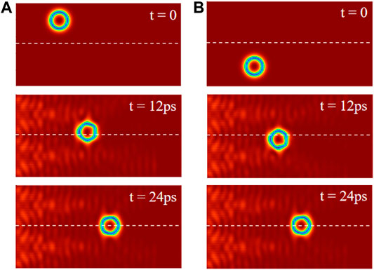
FIGURE 2. The motion of the AFM skyrmion with different initial positions at (A) upside and (B) bottom side. The white dashed line indicates the intersection of the two spin wave sources.
The simulated skyrmion position as a function of time is presented in Figure 3. On one hand, the skyrmion is quickly relaxed to the equilibrium y-position at y = 50 (dashed line in Figure 3A) as discussed above, although a weak oscillating behavior is noticeable. On the other hand, the evolutions of the x-position for the two cases are almost the same, as shown in Figure 3B. It is noted that the injected spin waves are unavoidable dissipated as it propagates, contributing to the decrease of the skyrmion speed (slope of the position curve).
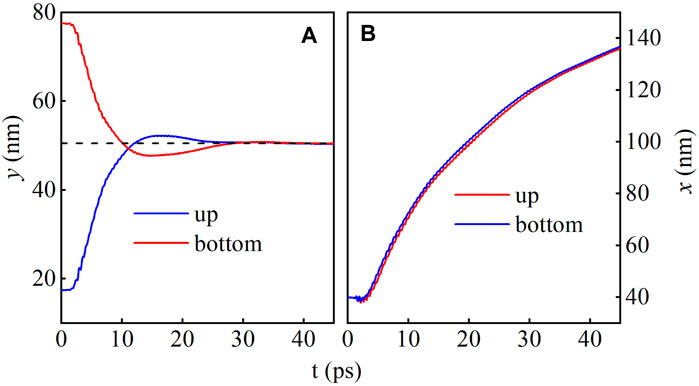
FIGURE 3. The evolution of the (A) y and (B) x coordinates of the AFM skyrmions. The black dashed line represents the intersection of the spin wave sources.
Subsequently, we investigate the dependence of the speed of the skyrmion on several parameters and present the simulated results in Figure 4. Here, the speed is estimated from the average one in the region x = (110, 130). The calculated velocity vx-Double as a function of ω for h0 = 600 mT is shown with red squares in Figure 4A. Two frequencies at ω = 1.6 THz and 2.2 THz are observed with local maximum values vx ∼ 450 m/s, which is comparable to the current driven one. The speed of the skyrmion driven by the y linearly polarized spin wave vx-Linearly is also estimated to be vx ∼ 200 m/s, which is rather stable for various ω but much smaller than the maximum value driven by the double circularly polarized spin waves. To have a direction comparison, the speeds along the x direction vx and y-direction vy of the skyrmion driven by right-handed spin wave are also presented. Two local maximum vx ∼ 550 m/s are estimated at ω = 1.7 THz and 2.0 THz, and the maximum vy ∼ 850 m/s is estimated at ω = 2.1 THz. However, in all investigated ω regions, vy > vx is estimated, demonstrating the strong skyrmion Hall effect. Thus, particular ω could be chosen in the proposed method to obtain large speed in the absence of skyrmion Hall motion.
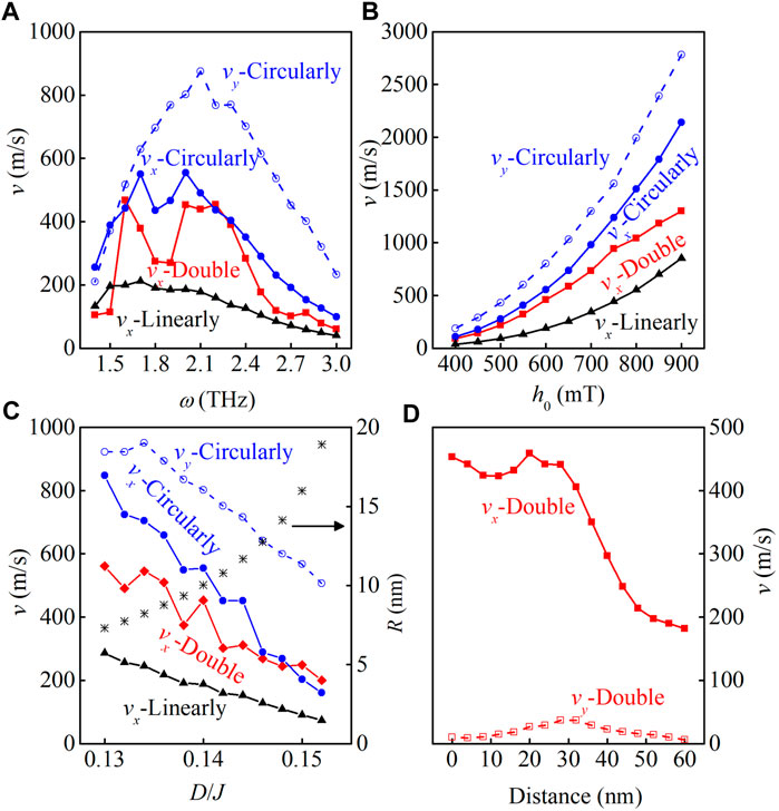
FIGURE 4. The simulated speeds of the skyrmion driven by the double circularly polarized spin waves vx-Double, by the y linearly polarized spin waves vx-Linearly, by the right-handed polarized spin waves vx-Circularly and vy-Circularly as functions of (A) ω for h0 = 600mT, (B) h0 for ω = 2 THz, and (C) D for h0 = 600 mT and ω = 2 THz. (D) The simulated vx and vy as function of the distance between the two spin wave sources for h0 = 600 mT and ω = 2 THz. The simulated skyrmion radii are also presented in (C).
The magnitude of the spin wave is mainly controlled by h0. Thus, with the increase of h0, the speed of the skyrmion is increased, as shown in Figure 4B, which presents the estimated speeds of the skyrmion as functions of magnitude driven by various methods at ω = 2 THz. For h0 < 750 mT, all the estimated speeds increase appropriately with h20 raised from the energy transfer between the spin wave and skyrmion, noting that the energy of the spin wave linearly increases with h20. However, with the further increase of h0, the skyrmion speed driven by the double circularly polarized spin waves increases much slowly. In some extent, the interference between the two kinds of spin waves is strengthened, strongly limiting the increase of the skyrmion speed.
Furthermore, the skyrmion radius depending on several parameters of the system such as the DMI and anisotropy also affects the skyrmion speed. In Figure 4C, the simulated speeds as functions of D driven by various methods for ω = 2.0 THz and h0 = 600 mT are presented. Moreover, the calculated skyrmion radii are also given to help one to understand the results easier. The same as our earlier theoretical calculations, the radius is increased with the increase of D [33, 34]. On one hand, the interacting area between the spin wave and skyrmion is enlarged [35], resulting in the increase of interacting force and skyrmion speed. On the other hand, the mass of the skyrmion is also increased with the increase of the radius [36], decreasing the skyrmion speed. As a result, the competition between the above two factors determines the speed of the skyrmion. For the skyrmion driven by the linearly polarized spin wave, the speed monotonously decreases with the increase of D, demonstrating the dominant effect of the second factor. For the skyrmion driven by double and single circularly polarized spin waves, the oscillating decrease of vx is observed due to the competition between the two factors. Moreover, the two simulated vx are almost the same for D > 0.145, attributing to the increase of the component from the circularly polarized spin waves in the driving force.
Figure 4D shows the dependence of vx on the distance between the two spin wave sources for ω = 2.0 THz and h0 = 600 mT. It is clearly shown that in a rather large distance range 0–30 nm, a rather stable speed vx ∼ 500 m/s is obtained. Thus, the skyrmion dynamics is hardly affected by increasing the distance between the two spin wave sources due to the spreading of the spin waves, allowing one to choose proper distance between the two spin wave sources to save energy. Moreover, vy is rather small in the whole distance range, indicating again the well suppression of the skyrmion Hall motion.
The depinning behavior of skyrmion is a crucial issue considering the fact that there are inevitable defects in real materials. At last, we investigate the depinning behavior from the defect which is set in the intersection line, as shown in Figure 5. Here, additional anisotropy A(mzi)2 is used to describe the defect at site i, and we take D/J = 0.13. Figure 5A shows the trajectory of the skyrmion for A/J = 0.05, ω = 2 THz, and h0 = 800 mT. It is clearly shown that the skyrmion can pass through the defect directly. However, the energy barrier is high for large A, prohibiting the skyrmion go straightly through the defect [3]. Interestingly, the skyrmion can bypass the defect and then return to its presupposed orbit, as shown in Figure 5B, which presents the motion of the skyrmion for A/J = 0.15. More interestingly, the depinning effect still works in the system with randomly distributed defects for a high concentration 0.1%, as demonstrated in Figures 6A,B, where presents the skyrmion trajectory (green curve) for A/J = 0.05 and A/J = 0.15, respectively. Similarly, the skyrmions pass through the weak defects for A/J = 0.05 directly, while bypassing the strong defects for A/J = 0.15. Thus, the proposed method could be used to precisely drive the skyrmion motion along designed tracks.
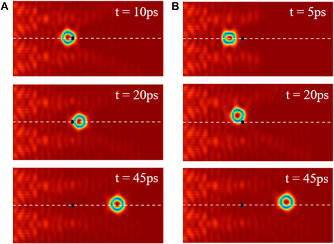
FIGURE 5. The AFM skyrmion motion in the presence of the defect for (A) A/J = 0.05 and (B) A/J = 0.15. The black dots are the defects, and the white dashed lines represent the intersection of the two spin wave sources.
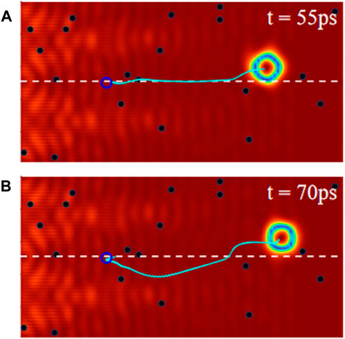
FIGURE 6. The AFM skyrmion motion trajectories (green curves) with defect concentration 0.1% for (A) A/J = 0.05 and (B) A/J = 0.15, where the initial positions of skyrmion are represented by the empty blue circles.
Most recently, the AFM skyrmions have been experimentally observed in antiferromagnets with synthetic structures and three sub-lattices [37], which could be used to check our simulations. The generation of the spin wave could be realized through applying an oscillating magnetic field with intensity h0 = 400–800 mT and frequency ω ∼ 2 THz [38], or by injecting spin current with intended polarizations [39, 40].
In summary, we propose a method to suppress the skyrmion Hall motion driven by circularly polarized spin waves in antiferromagnets. The application of the two circularly polarized spin waves drives the skyrmion motion straightly along the intersection line of the two spin wave sources. The skyrmion speed depending on these parameters of the spin waves and system is numerically simulated, and a comparison with those driven by other methods is provided. At last, two depinning behaviors of the skyrmion related to the strengths of the defect are discussed. Thus, the proposed method could be used in precisely modulating the skyrmion dynamics.
The raw data supporting the conclusions of this article will be made available by the authors, without undue reservation.
SG conceived the research project, SG and ZJ performed the computations. SG, YY, ZJ, TL, YL, and MQ commented the modeling and discussed the results. MQ and SG wrote the manuscript.
The work was supported by the Natural Science Foundation of China (Grant No. 51971096), the Science and Technology Planning Project of Guangzhou in China (Grant No. 201904010019), the Natural Science Foundation of Guangdong Province (Grant No. 2019A1515011028), Special Funds for the Cultivation of Guangdong College Students Scientific and Technological Innovation (Grant No. pdjh2020a0148), and National college students’ innovation and entrepreneurship training program (Grant No. 202110574049).
The authors declare that the research was conducted in the absence of any commercial or financial relationships that could be construed as a potential conflict of interest.
All claims expressed in this article are solely those of the authors and do not necessarily represent those of their affiliated organizations, or those of the publisher, the editors, and the reviewers. Any product that may be evaluated in this article, or claim that may be made by its manufacturer, is not guaranteed or endorsed by the publisher.
1. Fert A, Cros V, Sampaio J. Skyrmions on the Track. Nat Nanotech (2013) 8:152–6. doi:10.1038/nnano.2013.29
2. Nagaosa N, Tokura Y. Topological Properties and Dynamics of Magnetic Skyrmions. Nat Nanotech (2013) 8:899–911. doi:10.1038/nnano.2013.243
3. Iwasaki J, Mochizuki M, Nagaosa N. Universal Current-Velocity Relation of Skyrmion Motion in Chiral Magnets. Nat Commun (2013) 4:1463. doi:10.1038/ncomms2442
4. Boulle O, Vogel J, Yang H, Pizzini S, de Souza Chaves D, Locatelli A, et al. Room-temperature Chiral Magnetic Skyrmions in Ultrathin Magnetic Nanostructures. Nat Nanotech (2016) 11:449–54. doi:10.1038/nnano.2015.315
5. Büttner F, Lemesh I, Beach GSD. Theory of Isolated Magnetic Skyrmions: From Fundamentals to Room Temperature Applications. Sci Rep (2018) 8:4464. doi:10.1038/s41598-018-22242-8
6. Yuan HY, Wang XR. Skyrmion Creation and Manipulation by Nano-Second Current Pulses. Sci Rep (2016) 6:22638. doi:10.1038/srep22638
7. Silva RL, Silva RC, Pereira AR, Moura-Melo WA. Antiferromagnetic Skyrmions Overcoming Obstacles in a Racetrack. J Phys Condens Matter (2019) 31:225802. doi:10.1088/1361-648x/ab0abd
8. Kim K-W, Moon K-W, Kerber N, Nothhelfer J, Everschor-Sitte K. Asymmetric Skyrmion Hall Effect in Systems with a Hybrid Dzyaloshinskii-Moriya Interaction. Phys Rev B (2018) 97:224427. doi:10.1103/physrevb.97.224427
9. Bessarab PF, Yudin D, Gulevich DR, Wadley P, Titov M, Tretiakov OA. Stability and Lifetime of Antiferromagnetic Skyrmions. Phys Rev B (2019) 99(R):140411. doi:10.1103/physrevb.99.140411
10. Liang JJ, Yu JH, Chen J, Qin MH, Zeng M, Lu XB, et al. Magnetic Field Gradient Driven Dynamics of Isolated Skyrmions and Antiskyrmions in Frustrated Magnets. New J Phys (2018) 20:053037. doi:10.1088/1367-2630/aac24c
11. Barker J, Tretiakov OA. Static and Dynamical Properties of Antiferromagnetic Skyrmions in the Presence of Applied Current and Temperature. Phys Rev Lett (2016) 116:147203. doi:10.1103/physrevlett.116.147203
12. Zhang J, Zhang Y, Gao Y, Zhao G, Qiu L, Wang K, et al. Magnetic Skyrmions in a Hall Balance with Interfacial Canted Magnetizations. Adv Mater (2020) 32:1907452. doi:10.1002/adma.201907452
13. Zhang X, Zhou Y, Ezawa M. Antiferromagnetic Skyrmion: Stability, Creation and Manipulation. Sci Rep (2016) 6:24795. doi:10.1038/srep24795
14. Akosa C, Tretiakov O, Tatara G, Manchon A. Theory of the Topological Spin Hall Effect in Antiferromagnetic Skyrmions: Impact on Current-Induced Motion. Phys Rev Lett (2018) 121:097204. doi:10.1103/physrevlett.121.097204
15. Jin C, Song C, Wang J, Liu Q. Dynamics of Antiferromagnetic Skyrmion Driven by the Spin Hall Effect. Appl Phys Lett (2016) 109:182404. doi:10.1063/1.4967006
16. Göbel B, Mook A, Henk J, Mertig I. Antiferromagnetic Skyrmion Crystals: Generation, Topological Hall, and Topological Spin Hall Effect. Phys Rev B (2017) 96:060406(R). doi:10.1103/physrevb.96.060406
17. Buhl PM, Freimuth F, Blügel S, Mokrousov Y. Topological Spin Hall Effect in Antiferromagnetic Skyrmions. Phys Status Solidi RRL (2017) 11:1700007. doi:10.1002/pssr.201700007
18. Yuan HY, Liu Q, Xia K, Yuan Z, Wang XR. Proper Dissipative Torques in Antiferromagnetic Dynamics. EPL (2019) 126:67006. doi:10.1209/0295-5075/126/67006
19. Liang X, Zhao G, Shen L, Xia J, Zhao L, Zhang X, et al. Dynamics of an Antiferromagnetic Skyrmion in a Racetrack with a Defect. Phys Rev B (2019) 100:144439. doi:10.1103/physrevb.100.144439
20. Zhang X, Ezawa M, Xiao D, Zhao GP, Liu Y, Zhou Y. All-magnetic Control of Skyrmions in Nanowires by a Spin Wave. Nanotechnology (2015) 26:225701. doi:10.1088/0957-4484/26/22/225701
21. Yu H, Xiao J, Schultheiss H. Magnetic Texture Based Magnonics. Phys Rep (2021) 905:1–59. doi:10.1016/j.physrep.2020.12.004
22. Wang ZY, Yuan HY, Cao YS, Li ZX, Duine RA, Yan P. Magnonic Frequency Comb through Nonlinear Magnon-Skyrmion Scattering. Phys Rev Lett (2021) 127:037202. doi:10.1103/physrevlett.127.037202
23. Iwasaki J, Beekman AJ, Nagaosa N. Theory of Magnon-Skyrmion Scattering in Chiral Magnets. Phys Rev B (2014) 89:064412. doi:10.1103/physrevb.89.064412
24. Shen M, Zhang Y, Ou-Yang J, Yang X, You L. Motion of a Skyrmionium Driven by Spin Wave. Appl Phys Lett (2018) 112:062403. doi:10.1063/1.5010605
25. Proskurin I, Stamps RL, Ovchinnikov AS, Kishine J-I. Spin-Wave Chirality and its Manifestations in Antiferromagnets. Phys Rev Lett (2017) 119:177202. doi:10.1103/physrevlett.119.177202
26. Daniels MW, Yu W, Cheng R, Xiao J, Xiao D. Topological Spin Hall Effects and Tunable Skyrmion Hall Effects in Uniaxial Antiferromagnetic Insulators. Phys Rev B (2019) 99:224433. doi:10.1103/physrevb.99.224433
27. Jin Z, Meng CY, Liu TT, Chen DY, Fan Z, Zeng M, et al. Magnon-driven Skyrmion Dynamics in Antiferromagnets: Effect of Magnon Polarization. Phys Rev B (2021) 104:054419. doi:10.1103/physrevb.104.054419
28. Pickart SJ, Collins MF, Windsor CG. Spin‐Wave Dispersion in KMnF3. J Appl Phys (1966) 37:1054–5. doi:10.1063/1.1708332
29. Heeger AJ. Spin-Wave Instability and Premature Saturation in Antiferromagnetic Resonance. Phys Rev (1963) 131:608–16. doi:10.1103/physrev.131.608
30. Qaiumzadeh A, Kristiansen LA, Brataas A. Controlling Chiral Domain Walls in Antiferromagnets Using Spin-Wave Helicity. Phys Rev B (2018) 97:020402(R). doi:10.1103/physrevb.97.020402
31. Saiki K. Resonance Behaviour in Canted Antiferromagnet KMnF3. J Phys Soc Jpn (1972) 33:1284–91. doi:10.1143/jpsj.33.1284
32. Lan J, Yu W, Xiao J. Antiferromagnetic Domain wall as Spin Wave Polarizer and Retarder. Nat Commun (2017) 8:178. doi:10.1038/s41467-017-00265-5
33. Jin Z, Liu T, Li W, Zhang X, Hou Z, Chen D, et al. Dynamics of Antiferromagnetic Skyrmions in the Absence or Presence of Pinning Defects. Phys Rev B (2020) 102:054419. doi:10.1103/physrevb.102.054419
34. Wang XS, Yuan HY, Wang XR. A Theory on Skyrmion Size. Commun Phys (2018) 1:31. doi:10.1038/s42005-018-0029-0
35. Schütte C, Garst M. Magnon-skyrmion Scattering in Chiral Magnets. Phys Rev B (2014) 90:094423. doi:10.1103/physrevb.90.094423
36. Tveten EG, Qaiumzadeh A, Tretiakov OA, Brataas A. Staggered Dynamics in Antiferromagnets by Collective Coordinates. Phys Rev Lett (2013) 110:127208. doi:10.1103/physrevlett.110.127208
37. Legrand W, Maccariello D, Ajejas F, Collin S, Vecchiola A, Bouzehouane K, et al. Room-temperature Stabilization of Antiferromagnetic Skyrmions in Synthetic Antiferromagnets. Nat Mater (2020) 19:34–42. doi:10.1038/s41563-019-0468-3
38. Cheng R, Daniels MW, Zhu J-G, Xiao D. Antiferromagnetic Spin Wave Field-Effect Transistor. Sci Rep (2016) 6:24223. doi:10.1038/srep24223
39. Cheng R, Xiao J, Niu Q, Brataas A. Spin Pumping and Spin-Transfer Torques in Antiferromagnets. Phys Rev Lett (2014) 113:057601. doi:10.1103/physrevlett.113.057601
Keywords: antiferromagnetic skyrmion, spin waves, dynamics, Hall motion, speed
Citation: Guan SH, Yang Y, Jin Z, Liu TT, Liu Y and Qin MH (2021) Suppression of Skyrmion Hall Motion in Antiferromagnets Driven by Circularly Polarized Spin Waves. Front. Phys. 9:754869. doi: 10.3389/fphy.2021.754869
Received: 07 August 2021; Accepted: 27 September 2021;
Published: 03 November 2021.
Edited by:
Huaiyang Yuan, Utrecht University, NetherlandsReviewed by:
Farhad Sattari, University of Mohaghegh Ardabili, IranCopyright © 2021 Guan, Yang, Jin, Liu, Liu and Qin. This is an open-access article distributed under the terms of the Creative Commons Attribution License (CC BY). The use, distribution or reproduction in other forums is permitted, provided the original author(s) and the copyright owner(s) are credited and that the original publication in this journal is cited, in accordance with accepted academic practice. No use, distribution or reproduction is permitted which does not comply with these terms.
*Correspondence: M. H. Qin, cWlubWhAc2NudS5lZHUuY24=
Disclaimer: All claims expressed in this article are solely those of the authors and do not necessarily represent those of their affiliated organizations, or those of the publisher, the editors and the reviewers. Any product that may be evaluated in this article or claim that may be made by its manufacturer is not guaranteed or endorsed by the publisher.
Research integrity at Frontiers

Learn more about the work of our research integrity team to safeguard the quality of each article we publish.