 Arash Mafi
 John Ballato
95% of researchers rate our articles as excellent or good
Learn more about the work of our research integrity team to safeguard the quality of each article we publish.
Find out more
REVIEW article
Front. Phys. , 26 November 2021
Sec. Optics and Photonics
Volume 9 - 2021 | https://doi.org/10.3389/fphy.2021.736774
This article is part of the Research Topic Localization of Light in Randomly Disordered and Quasiperiodic Systems View all 7 articles
Nearly a decade ago, transverse Anderson localization was observed for the first time in an optical fiber with a random transverse refractive index profile. This started the development of a whole new class of optical fibers that guide light, not in a conventional core-cladding setting based on total internal reflection, but utilizing Anderson localization, where light can guide at any location across the transverse profile of the fiber. These fibers have since been used successfully in high-quality endoscopic image transport. They also show interesting nonlinear and active (lasing) properties with promising applications. This review will cover a brief history of these fibers with personal accounts of the events that led to their development in our research groups. It will then follow with recent progress and future perspectives on science and applications of these fibers.
Nearly a decade ago, transverse Anderson localizing optical fiber (TALOF) was introduced as a novel class of optical fibers with intriguing unconventional properties [1, 2]. There has since been a rapidly growing interest in these fibers in academia and industry with their realization covering a broad range of applications including beam multiplexing [3], ultra-bend performance [3], image transport [4–8], nonlocal nonlinear behavior [9, 10], sharp focusing and wave-front shaping [11, 12], data packing using single photons [13], and random lasing [14]. In this article, we review the current progress and challenges in the development and application of TALOFs and speculate on their future potential.
TALOFs are not typical core-cladding optical fiber structures. Their refractive index profile is random (disordered) in the transverse cross-section of the fiber but, ideally, does not change along the fiber length. TALOFs guide light, not by total internal reflection as in conventional fibers but via a mechanism referred to as transverse Anderson localization (TAL). TAL is Anderson localization (AL) in a longitudinally invariant and transversely disordered optical structure. AL is the absence of diffusive wave transport in highly disordered scattering media [15–21]. Although our focus here is on optical structures, AL has been observed in various physical systems that are described by waves, including the quantum wave function of an electron governed by the Schrödinger equation (15, 22–24], matter waves and Bose-Einstein condensates [25–27], quantum fields such as photons [28–31], as well as classical waves such as acoustics/elsatics [32–34], and electromagnetics [35–38].
Many research papers and review articles have discussed optical realizations of AL over the years [39–43]. Optics has access to a broad range of materials and characterization tools without requiring prohibitively complicated or expensive infrastructure and is a unique platform to study AL phenomena [44–49], including its interaction with nonlinearity [9, 10, 50–52]. Over the years, many attempts have been made to observe AL of light in a three-dimensional (3D) optical setting, including some recent demonstrations [53–55]. To observe 3D Anderson localization, a large refractive index contrast is typically required. Unfortunately, such large refractive index contrasts are generally accompanied by considerable losses in materials such as in metals. Because it is difficult to differentiate between the exponential decay of the optical field due to AL and that associated with loss, 3D AL of light remains a subject of active on-going research.
The possibility of TAL in optics was first explored in a pair of visionary theoretical papers independently by Abdullaev et al. [56] in 1980 and De Raedt et al. [57] in 1989. They argued that if a finite beam of light is coupled to the (transverse) cross-section of a dielectric that is transversely disordered and longitudinally invariant, it can remain spatially localized in the cross-section while propagating freely along the dielectric. The extent of the transverse localization depends on the strength of the randomness–weak randomness results in weak localization (large localization radius) and strong randomness results in strong localization (small localization radius). TAL is ubiquitous in transversely disordered lossless dielectrics with an infinitely large cross-section, regardless of the amount of disorder. However, for structures with a finite cross-section such as optical fibers, the transverse scattering must be sufficiently strong such that the localization radius stays smaller than the transverse dimensions of the dielectric to avoid boundary-induced complications [50, 58–61].
The TAL structure proposed by Abdullaev et al. and De Raedt et al. are conceptually close but different in implementation. Abdullaev et al. [56] proposed the structure sketched in Figure 1, which is a two-dimensional (2D) array of coupled optical fibers. The design parameters of the optical fibers are slightly different (random); therefore, they support optical modes with different propagation constants [62]. As such, the modes cannot couple to one another efficiently and the amplitude of optical field injected into one fiber decreases exponentially as it is coupled into the neighboring fibers. The tunneling efficiency decreases in the presence of larger randomness. In the language of supermodes, which are the collective modes of the entire structure, one observes localized modes with their radius representing the disordered waveguide’s localization radius.
FIGURE 1. A conceptual sketch of a 2D randomized array of optical fibers to observe TAL as proposed by Abdullaev et al. [56].
The structure proposed by De Raedt et al. [57] takes a different form from that proposed by Abdullaev et al. In Figure 2 we show a waveguide similar to an optical fiber but without the core and cladding structure. The refractive index across the waveguide is pixelated into small squares of nearly wavelength-size side-widths. Each pixel is assigned a refractive index of n1 or n2 with a 50–50 chance. Therefore, the transverse refractive index profile of the waveguide is randomized, while the index remains invariant in the longitudinal direction. In the absence of such randomization, for example, when the entire waveguide is made from the same glass, an optical field that is launched into the facet rapidly diffracts as it propagates along the waveguide and fills the entire cross-section of the waveguide. However, for the disordered structure, the optical field scatters strongly in the transverse direction from the pixelated structure and remains localized, after a brief expansion (diffusion), as it freely propagates along the fiber. The localization radius can be generally reduced by increasing the scattering cross-section, which can be achieved, for example, by increasing the refractive index contrast Δn = |n2 − n1| of the two constituent materials. The original TALOF structures developed in our groups and most of the other practical structures follow the design proposed by De Raedt et al. [57], which will be discussed in the rest of the review article.
FIGURE 2. A conceptual sketch of the random dielectric medium by De Raedt et al. [57] for the observation of the TAL of light. The cross-section pixels represent the refractive index values of n1 and n2.
This Section offers personal accounts of the events that led to the development of the first TALOFs and is written as a first-person narrative by the Authors. In Figure 3, we present a chronology of selected TALOF “firsts,” which will be discussed in more detail throughout the text.
FIGURE 3. Chronology of selected TALOF “firsts” including advances in materials (yellow) and applications (red).
It has been quite a while, and I have to rely on my fading memory to reconstruct the events, so I may not get the exact dates right but will do my best to capture the sequence of events. Sometime in late 2008, I recall having a discussion with Karl W. Koch of Corning Incorporated, who introduced me to a couple of interesting papers on the observation of TAL [50, 63]. We briefly discussed that it would be nice to observe TAL in optical fibers. After that discussion, I asked Krishna Mohan Gundu, who was a postdoctoral researcher in my group at the University of Wisconsin-Milwaukee (UWM), to write a scalar beam propagation code and reproduce the results of De Raedt et al. [57]. After this exercise, we gained some confidence, came up with a few ideas on how to make the fiber, and decided to look for funding to support the research. We chose the Grant Opportunities for Academic Liaison with Industry (GOALI) program at the National Science Foundation (NSF). NSF-GOALI allowed us to forge a university-industry alliance. The officials at UWM and Corning were quite accommodating in letting us work on this topic and quickly came to an agreement on intellectual property rights and freedom to publish the results. We submitted the grant application in February 2010 and received the funding to start the research in August of the same year.
When we received the funding, I asked Salman Karbasi, who was a relatively new graduate student in my research group to focus his efforts on this research. Over the next few months, we brainstormed on various ways to fabricate the disordered fiber to observe TAL, while Salman was also developing his own beam propagation code. For a while, we were stalled and did not know how to approach the fiber fabrication problem. Finally, in our hopeless attempts, we decided to shift the work to microwave frequencies, essentially scaling up the structure by three orders of magnitude. Figure 4 shows one of the structures we built by filling a large pipe with candle and drilling air-holes into the structure using long drill bits in the Civil Engineering Laboratory at UWM.
FIGURE 4. The pictures show a large pipe filled with candle to observe TAL in the microwave spectrum. The random air-holes are drilled into the candle along the pipe to create the required random refractive index contrast across the waveguide.
While we were working on the candle waveguide, we came up with the idea of assembling the structure from polymer fibers. I looked on the web and found Paradigm Optics Incorporated that was specialized in polymer fiber drawing. I contacted the President and CEO David Welker, and mentioned what we were looking for, and he helped us select the right polymer fibers. Of course, we did not disclose much about our intentions at the time due to intellectual property restrictions. David Welker agreed to draw the fiber for a fee, and we received 80,000 strands of polyester (PS) and polymethyl methacrylate (PMMA) fibers from Paradigm Optics. We randomized and assembled the fibers into a square holder as shown in Figure 5. We shipped the randomized fibers back to Paradigm Optic, where they made it into a preform, drew the fiber, and sent it back to us. The first attempt was a total failure. However, we decided not to give up and thought that perhaps the randomization process was flawed. When we received the second set, several students worked together for 3 weeks to mix the fibers randomly. The biggest challenge, I recall, was the static charge build-up that prevented us from separating and mixing the fibers easily. After we felt comfortable with the extent of randomization, we shipped the assembled fibers back to Paradigm Optics, and they sent us the newly drawn fibers a few weeks later, in July 2011.
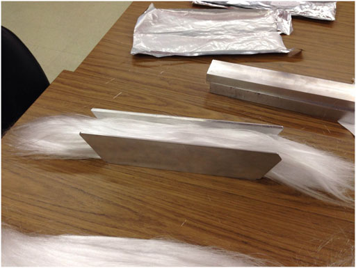
FIGURE 5. The polyester and PMMA fiber strands are randomly mixed and assembled into a holder to create the polymer TALOF preform.
After we received the fibers, Salman went to the laboratory, spent a day or two aligning the optics, and observed TAL by coupling a He-Ne laser into the fiber in late July 2011. It was a joyful event for all of us, and of course, we decided to abandon the microwave project and the candles and focused on the newly developed Anderson localizing optical fiber. We decided to run many tests on our fibers and ensuring that our results were robust. It took us a while before we were fully convinced that we had observed transverse Anderson localization for the first time in an optical fiber. The manuscript was submitted to Optics Letters on April 11, 2012, revised and accepted on April 26, 2012, and was posted online the next day.
While the polyester/PMMA fibers provided a necessary proof-of-principle, the transition to an all-glass TALOF was well-appreciated as being a critical step towards greater utility and practicality. Arash was aware that our Group at Clemson University had a long history of fabricating a variety of unusual fibers from unusual combinations of materials and a general willingness to try almost anything once. He contacted me around the end of 2011 to talk through an all-glass TALOF and solicit our collaboration.
Intrigued by the physics and opportunity, we set out thinking about how to best achieve a glass TALOF. Admittedly, the idea of drawing lengths from two different glasses and then stacking them into random arrays by the tens-of-thousands was not appealing. Further, and in equal candor, we were not sure it would work and did not want to spend significant time or money on the effort. We decided to try satin quartz, which is comprised of silica with small air bubbles entrained in it. Satin quartz is used by artisans because the small bubbles provide a white iridescence. Most importantly, it is cheap, and we happened already to have some for an unrelated project.
The satin quartz rod was drawn on 16 April 2012. After trying several settings to achieve reasonable draw tension and diameter control, 150 m of fiber was drawn at a temperature of about 1850°C. We did not hear anything back for several months until Arash mentioned, somewhat in passing, that the fiber had worked and that a manuscript was being drafted. We were as pleased that the satin quartz fiber worked as we were surprised, and I remember unfortunately thinking those famous last words “well that was easy.” The manuscript was submitted for consideration on 16 August 2012, published on 1 October 2012 [64], and subsequently highlighted in Spotlight on Optics [64].
The first two early demonstrations of TALOFs were reported in a polymer design in Ref. [1] and a silica structure in Ref. [64]. In the following, we discuss these developments.
The first demonstration of TALOF was reported in 2012 by Karbasi et al. [1] in a polymer structure. The design followed the structure proposed by De Raedt et al. [57] in their 1989 paper. We briefly discussed this in Section 2.1. To fabricate the first TALOF, Karbasi et al. used the stack-and-draw method to create a disordered transverse profile with the low-index component, polymethyl methacrylate (PMMA) with a refractive index of 1.49, and a high-index component, polystyrene (PS) with a refractive index of 1.59. As shown in Figure 5, 40,000 pieces of PS and 40,000 pieces of PMMA fibers were randomly mixed [65], fused together in a square container, and redrawn to a fiber with a nearly square profile and approximate side-width of 250 µm, as shown in the left panel in Figure 6. The right panel shows the zoomed-in scanning electron microscope (SEM) image of an approximately 24 µm-wide region on the tip of the fiber. To enhance the contrast between the PS and PMMA regions, the fiber tip was exposed to an ethanol solvent to dissolve the PMMA, so the darker regions are PMMA, and lighter regions are PS. The typical random feature size in the structure shown in Figure 6 is around 0.9 µm.
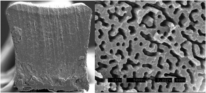
FIGURE 6. In the left panel, we show the cross-section of the polymer disordered fiber from Ref. [1], which has a nearly square profile with an approximate side-width of 250 µm. In the right panel, we show the zoomed-in SEM image of a 24 µm-wide region on the tip of the fiber. For this picture, to enhance the contrast between PMMA and PS, the PMMA near the surface of the tip has been etched by a solvent. Feature sizes are around 0.9 µm, and darker regions are PMMA. Reprinted/Reproduced with permission from Optics Letters, 2012 [1], and the Optical Society of America.
Karbasi et al. butt-coupled a small-core optical fiber to the polymer TALOF and showed that He-Ne laser light launched from the fiber remains transversely localized while propagating through the polymer TALOF. Furthermore, they scanned the input beam across the input facet of the TALOF and observed that the output beam followed the transverse position of the incoming beam [2]. Upon further analysis, they showed that the launched beam went through a brief initial expansion (transverse diffusion), and the expansion was arrested after propagating for ∼2cm, after which the TAL eventually took over. They reported the average value of the beam radius for the 100 measured near-field beam intensity profiles to be ξavg = 31µm, with a standard deviation σξ = 14 µm. The longest piece of fiber in which they observed TAL was a 60 cm segment. The visibly large variations in the diameter of the fiber with a nominal period of shorter than 1 m prevented the observation of TAL in longer segments. This variation was likely due to thermal instabilities in the drawing process. Moreover, the observed attenuation was quite high, 0.1–1.0 dB/cm for initial samples, which can be attributed to the less-than-clean assembly process with exposure of the fiber strands to room dust over the 3 weeks of randomizing and assembly on an office table, and the diameter variation of the fiber.
After the observation of TAL in the polymer TALOF, Karbasi et al. in a follow-up paper, conducted a detailed analysis of the effect of the refractive index contrast, fill-fraction, and random site size on the localization radius [2]. They observed that at least for Δn ≤ 0.5, a stronger TAL and smaller localization radius can be observed as the index contrast increases. However, the analysis was performed with the scalar approximation, which is generally valid when index contrasts are small. The jury is still out for larger values of the index contrast, especially if Δn becomes so large that the vectorial nature of the optical field must be taken into account [66]. As for the optical fill-fraction, our current understanding is that the 50–50 percent mixture of the high and low index constituent materials results in the strongest transverse scattering. However, this hypothesis has been tested only numerically and for transverse index variations on the order of a wavelength. It is possible that if the air-holes are much smaller than a wavelength, the 50–50 percent would not be the ideal ratio. As for embedding the optimal 50% ratio of the low index (possibly air) material in a higher index network, the 50% value is below the percolation threshold (59.27%) of a square lattice; therefore, the host material with the higher refractive index remains generally connected in the long-range, making the TAL non-trivial, i.e., light localization is not merely due to the disconnected clusters of the higher index material.
Another important observation made in Ref. [2] is that the statistical distribution of the mode field diameters follows a nearly Poisson-like distribution. It is observed that in the presence of a stronger transverse scattering, not only does the localization radius decrease due to a stronger TAL, but the mode-to-mode variations in the localization radius also decrease. In other words, a stronger localization is always accompanied by more uniformity of the localized modes. This is a critical observation because it sets the stage for making a practical TALOF for real-life applications. These observations led the team to look for mechanisms to increase the scattering strength by creating a larger index contrast, which eventually led to a glass-air disordered fiber structure. Another issue that was explored was the impact of the random site size on the localization radius. We will discuss this issue in some detail in Subsection 4.1.
The first observation of the TAL in a silica fiber was reported by Karbasi et al. [64] in 2012. As already elaborated in Section 2.2, this glass-air disordered fiber was fabricated in Ballato’s group at Clemson University. The preform was made from “satin quartz” (Heraeus Quartz), which is a porous artisan glass. The air-holes in the porous glass structure became elongated air channels in the fiber drawing process. The final structure resembled the design proposed by De Raedt et al. [57], with n1 = 1.0 and n2 = 1.46. In Figure 7, we show SEM images of the cross-section of this fiber, with the right panel showing a zoomed-in image. The black dots are air-holes embedded in the light-gray background matrix of silica. The diameter of the fiber shown in the left panel of Figure 7 is around 250 µm. The diameters of the air-holes vary between 0.2 and 5.5 µm. At the center of the fiber, the air-hole fill-fraction was reported to be nearly 2%, while increasing to around 7% near the edges; therefore, TAL was only observed near the periphery of the fiber. The observation of TAL near the boundary rather than the center was an issue that caused a bit of concern, considering the perceived delocalizing impact of the boundaries in disordered TAL systems [58, 67–69]. which was subsequently addressed in some detail in Ref. [61].
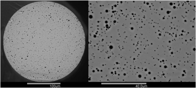
FIGURE 7. The left panel shows that SEM image of the silica optical fiber with random air-holes reported in Ref. [64] and drawn at Clemson University. The right panel shows a zoomed-in SEM image of the same fiber. Reprinted/Reproduced with permission from Optical Material Express, 2012 [64], and the Optical Society of America.
In 2014, Chen and Li [70] at Corning Incorporated reported another successful attempt in observing TAL in an air-glass TALOF. They observed TAL in structures with significantly lower air fill-fraction than those reported by Karbasi et al. [64]. While this requires further investigation, it is quite possible that this can be attributed to the far-subwavelength size of the transverse scattering centers and the much higher scattering center density (air-line density) compared with the structure in Figure 7.
There have since been other successful attempts is observing TAL in glass-based fibers. Starting in 2017, Axel Schülzgen’s group at CREOL, University of Central Florida, have reported various TALOF structures using the stack-and-draw technique [6, 71]. The stack-and-draw process consists of randomly mixing thousands of silica capillaries with different diameters and air-hole diameters and assembling them in a jacket tube to make the preforms. The preforms are subsequently drawn to desired diameters. For example, they reported drawing a fiber with the inner diameter of the randomly disordered region at 278 μm, and the outer diameter of 414 µm. For this particular fiber, they reported an air-filling fraction of about 28.5% where the air-hole areas ranged from 0.64 µm2 to over 100 μm2, with 2.5 µm2 being the peak of the statistical distribution. They have since refined the fiber fabrication process and have reported excellent image transport properties that will be discussed in Section 4.
Another more recent successful development of glass TALOF, as early as 2019, is by Yasutake Ohishi’s research group at the Toyota Technological Institute in Japan [72]. They reported the fabrication of all-solid all-glass disordered fiber structures using tellurite optical glasses that can be used for near-infrared image transport. The two-glass drawing process can potentially result in undesirable stresses and cracks. To avoid this issue, they managed to developed two tellurite glasses with high compatibility in thermal and mechanical properties. The two tellurite glasses were made of TeO2, Li2O, WO3, MoO3, Nb2O5 (TLWMN) and TeO2, ZnO, Na2O, La2O3 (TZNL) with the adequately large refractive index contrast of Δn = 0.095. TLWMN and TZNL glass rods were drawn down at 440°C to fibers whose diameters were 100 µm using a home-designed fiber drawing tower. They followed a stack-and-draw process, similar to that of the polymer fiber reported in Ref. [1]. They reported the transport of optical images through the all-solid tellurite-glass TALOF, 10 cm long, in the wavelength range of 1.44–1.60 µm.
The basis for much of the TALOF materials development, at least as relates to all-glass versions, stems from the original work on phase-separated glasses [73]. Here, microscopic secondary phase regions were formed throughout the volume, which subsequently were elongated under strain leading to the observation of localization [74]. The intervening 35 years before this seminal work in glasses and the eventual realization of Anderson localization in (glass) optical fibers was, presumably, due largely to the lack of an obvious application, particularly as telecommunications pulled all attention for glass optical fiber materials and manufacturing. However, over the past decade, numerous innovations with respect to TALOFs, and the materials from which they are made, has been achieved. From a materials perspective, silica remains the dominant material, unsurprising given its prevalence, strength, and low optical losses. Silica-based TALOFs are routinely fabricated using both Chemical Vapor Deposition (CVD) [70] and stack-and-draw fabrication methods [6]. That said, important advancements have been made using tellurite glasses, which extends the utility of TALOFs into the infrared spectral region [75–77] and offers the potential for infrared nonlinear fibers.
Publications do, of course, focus attention on what is deemed successful. That which is not often remains in the dark. Provided here is a brief discussion of what did not work, at least to-date, some of which is highlighted in Ref. [78]. It is useful to remember first the general design considerations: 1) large index difference between the two materials comprising the TALOF, 2) a fill-factor of approximately 50%, 3) the size of the phases being about the wavelength of the light being employed, and 4) these idealized constraints in a structure that possesses transverse randomness but longitudinal invariance. The latter suggests the stack-and-draw of a random ensemble of canes into fiber where the canes possess a high index cores of reasonably large diameter relative to the cane outer diameter. The highest index core phase made, to the Author’s best knowledge, into a glass-clad (index ∼ 1.44) optical fiber is that of crystalline semiconductors, specifically Ge [79] and Si [80], with refractive indices of 4 and 3.5, respectively. Several attempts at a Si/SiO2 TALOF were ultimately unsuccessful since the drawing down to smaller dimensions either led to oxidation of the Si or dimensional instabilities due to Plateau-Rayleigh phenomena. Efforts at less extreme index contrasts were successful, particularly those employing a “hybrid” approach of using the molten core method to create novel core material canes followed by stack-and-draw to fabricate longitudinally invariant TALOFs from random stacks of said canes. In particular, core glasses in the strontium aluminosilicate system, with index of about 1.53, provided to be effective.
Perhaps the most successful application of TALOFs has been so far in imaging. This possibility was highlighted first in a paper by Karbasi et al. in Ref. [3], which showed that multiple beams can propagate simultaneously in TALOF with minimal distortion even when the fiber is bent. In a subsequent paper, Karbasi et al. [4] used simulation in a 1D structure to show that the introduction of disorder in an originally periodic structure significantly improves the image transport capabilities. Motivated by these findings, in Ref. [5], Karbasi et al. explored image propagation in the TAL polymer fiber of Ref. [1] (see Figure 5). They butt-coupled a 1951 USAF resolution test chart to the input end of the fiber–the test chart can be briefly described as a stencil into which small numbers and bars are carved. They illuminated the test chart from the input tip and images the output of the fiber on a CCD camera. The polymer TALOF provided high quality image transportation as highlighted in Figure 8 and Karbasi et al. showed that the image transport quality was comparable with or better than some of the best commercial multicore imaging fibers, with less pixelation and higher contrast. The approximate width of the point-spread function was calculated to be smaller than 10 μm at 405 nm wavelength for this TALOF in Ref. [2].
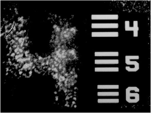
FIGURE 8. Transported images of numbers “4” through a 5 cm TALOF is shown along with a section of the 1951 U.S. Air Force resolution test chart (1951-AFTT) used in the experiment. The image of the number is 120 µm long. Details can be obtained in Reference [4].
Some of the most intriguing imaging results using TALOFs have been obtained in Axel Schülzgen’s group at CREOL, University of Central Florida, since 2017 [6–8, 71, 81–90]. Over the years, they have continuously improved the quality of the stack-and-draw TALOFs, lowered the attenuation, and have improved the image quality transport. Most notably, they have applied deep-learning techniques to improve the quality of the image transport in these fibers. In a recent publication, they utilized a deep convolutional neural network and trained it to classify the output images and tested on images never seen, namely, images collected when the fiber is bent or when the fiber facet is placed several millimeters away from the object without any distal optics. Their work is a considerable advancement compared with previous reports of image transport in multimode fibers, which are susceptible to bending distortions [91].
There has been a series of exciting papers from Yasutake Ohishi’s research group at the Toyota Technological Institute in Japan on near-infrared (NIR) optical image transport in TALOFs. Their work started in 2016 focused on the fabrication of the first all-solid tellurite optical glass rod for NIR imaging [72, 75–77, 92–94]. In Ref. [72], they reported a refractive index contrast of Δn = 0.095 and observed TAL and image transport at the NIR optical wavelength of 1.55 µm. Most recently, they reported the fabrication and analysis of chalcogenide TALOFs (As2Se3/AsS2 and AsSe2/As2S5) for mid-IR image transport [95, 96]. So far, they have reported the observation of TAL in the chalcogenide TALOF and actual image transport is yet to be demonstrated in these fibers.
In addition to these reported works on optical image transport using TALOFs, Leonetti et al. [13] propagated reconfigurable localized optical patterns in the polymer TALOF of Ref. [1] and encoded up to six bits of information in the localized channels, even with a low photon count. The results they reported are interesting for the potential application of TALOFs in spatially multiplexed configurations for quantum information processing.
The issue of the wavelength dependence of the localization radius and optimal pixel size was initially explored in Ref. [2]. In this paper, Karbasi et al. claimed that a shorter wavelength decreases the localization radius, using both simulations and experiments, and that a larger pixel size at a given wavelength decreases the localization radius. They argued that these two claims are interdependent due to the scale invariance in Maxwell’s equations. However, by carrying out extensive numerical simulations in 1D [97], they observed that the optimum value of the pixel size is around half the free-space wavelength. A more recent experiment along with simulations presented in Ref. [98] cast doubt on the results of Ref. [2] and Ref. [97] on wavelength dependence of the localization radius. Schirmacher et al. [98] observed that the mean localization radius, over a reasonable range, shows no dependence on the wavelength. Schirmacher et al. argued that the experiments conducted in Ref. [2] had large error-bars, so their results were not conclusive. Moreover, the simulations conducted in Ref. [2] ignored a term proportional to the transverse gradient of the refractive index, as is common in fiber optic simulations. Apparently, this term is responsible for making the localization radius wavelength independent. However, detailed simulations performed in Ref. [97] correctly took the transverse gradient of the refractive index into account and still showed some wavelength dependence. Therefore, this issue is inconclusive, and the matter has yet to be settled.
To address these issues, detailed numerical simulations are essential. However, the size of the numerical problem is often extremely large. A TALOF has a typical transverse dimension of a couple of hundred microns or more, with index fluctuations that are subwavelength. Therefore, such a large structure may have to be discretized into an enormous mesh in typical numerical schemes such as the Finite Element Method. The extremely large number of modes adds to this complexity, and the fact that TALOFs are random fibers and must be studied statistically. Therefore, many simulations must be performed and the results must be averaged. Fortunately, Nature has been somewhat kind and accommodating. In many cases, results obtained by fully analyzing a TALOF allow us to make broad conclusions due to the self-averaging behavior of the large number of modes supported by TALOFs. In many cases, it may also be possible to get by with simulating a much smaller structure, using the scaling properties of TAL structures [16, 19, 20, 23, 99–103].
In addition to the problems stated above, the traditional study of TAL is based on launching a beam and analyzing its propagation along the waveguide. It is hard to ensure that the results are not biased by the choice of the initial launch condition. One way to address such issues is to analyze the TALOF using the modal method and calculate the mode-area (MA) probability density function (PDF) for these structures [104, 105]. The MA-PDF encompasses all the relevant statistical information on TAL; it is independent of the launch condition and relies only the physical parameters of the TALOF. An important observation in Refs. [104, 105] is that as the transverse dimensions of TALOF increase, the MA-PDF eventually converges to a final form, especially for the localized modes. It turns out that for many practical structures and designs, the MA-PDF converges for TALOF dimensions much smaller than the sizes used in practical applications. Therefore, one can potentially find all relevant statistical information of a TALOF by simulating a much smaller structure.
The interaction between nonlinearity and Anderson localization has been explored over the years with somewhat inconclusive results [51, 52, 63, 106–108]. There is evidence, at least in certain systems of interest, that a focusing Kerr-type nonlinearity may enhance the localization [63]. Other types of nonlinearity, such as thermally-induced ones, have also been observed to affect TAL [9]. An interesting recent development is the observation of nonlinear four-wave mixing (FWM) in an all-solid TALOF, which was fabricated by using a novel combination of the stack-and-draw and molten core methods [109]. This is potentially interesting in light of the fact that a TALOF is a highly multimode fiber and can provide ample multimodal phase-matching opportunities to observe FWM at many different wavelengths. The main advantage of a TALOF compared with a conventional highly multimode fiber is that it provides localized modes [110] with smaller effective areas and larger relative nonlinear coefficients, so the FWM process can be more efficient [52].
Regarding the progress on TALOF lasers, we point out that there is a large body of literature on random lasers, which is beyond the scope of this article but is covered in several review articles, including by D. S. Wiersma [111]. A notable work on TALOF-based random lasers is by Abaie et al. [14] who filled the air-holes of a glass-air TALOF with an active dye using capillary action to make a transversely disordered active medium. They pumped the TALOF-based dye laser and observed that the active TALOF results in a spectrally broad, and a stable highly directional laser beam. More research on TALOF lasers is presently conducted in Mafi’s and Ballato’s research groups.
TALOFs demonstrate many interesting linear and nonlinear properties, and we anticipate that we will see an expanded role for these fibers in photonics applications. Much of the novel properties of these fibers are driven by the multiplicity of modes that are highly localized. Therefore, future development activities will focus on making the localization radii as small as possible. For device applications, uniformity and reproduciblity can also be important. Fortunately, it appears that these issues are intimately tied to one another, and reducing the localization radius is accompanied by a smaller variation in localization radii. At present, several companies are keenly interested in commercializing TALOFs for imaging. We anticipate that endoscopic imaging in visible and near-IR would be the first real-life device application for TALOFs. Future improvements in nonlinear applications may include the simultaneous generation of many wavelengths using FWM or even making a broadband source of light comparable to light-emitting diodes or supercontinuum sources, centered around any visible or infrared wavelength. We also expect notable results in making relatively broadband and spatially incoherent (highly multimode) lasers for application in imaging and illumination.
All authors listed have made a substantial, direct, and intellectual contribution to the work and approved it for publication.
AM acknowledges the National Science Foundation award numbers 1807857 and 1029547, and JB acknowledges award number 1808232 for partially funding the research on TALOFs.
The authors declare that the research was conducted in the absence of any commercial or financial relationships that could be construed as a potential conflict of interest.
All claims expressed in this article are solely those of the authors and do not necessarily represent those of their affiliated organizations, or those of the publisher, the editors and the reviewers. Any product that may be evaluated in this article, or claim that may be made by its manufacturer, is not guaranteed or endorsed by the publisher.
AM would like acknowledge the contributions of S. Karbasi and B. Abaie for their work that has touched many aspects of TAL in various fiber-based systems. JB would like to acknowledge the contributions of T. Hawkins and M. Tuggle to the development of TAL materials and fibers.
1. Karbasi S, Mirr CR, Yarandi PG, Frazier RJ, Koch KW, Mafi A. Observation of Transverse Anderson Localization in an Optical Fiber. Opt Lett (2012) 37:2304–6. doi:10.1364/ol.37.002304
2. Karbasi S, Mirr CR, Frazier RJ, Yarandi PG, Koch KW, Mafi A. Detailed Investigation of the Impact of the Fiber Design Parameters on the Transverse Anderson Localization of Light in Disordered Optical Fibers. Opt Express (2012) 20:18692–706. doi:10.1364/oe.20.018692
3. Karbasi S, Koch KW, Mafi A. Multiple-beam Propagation in an Anderson Localized Optical Fiber. Opt Express (2013) 21:305–13. doi:10.1364/oe.21.000305
4. Karbasi S, Koch KW, Mafi A. Image Transport Quality Can Be Improved in Disordered Waveguides. Opt Commun (2013) 311:72–6. doi:10.1016/j.optcom.2013.08.042
5. Karbasi S, Frazier RJ, Koch KW, Hawkins T, Ballato J, Mafi A. Image Transport Through a Disordered Optical Fibre Mediated by Transverse Anderson Localization. Nat Commun (2014) 5:3362. doi:10.1038/ncomms4362
6. Zhao J, Lopez JEA, Zhu Z, Zheng D, Pang S, Correa RA, et al. Image Transport through Meter-Long Randomly Disordered Silica-Air Optical Fiber. Sci Rep (2018) 8:3065. doi:10.1038/s41598-018-21480-0
7. Zhao J, Sun Y, Zhu Z, Antonio-Lopez JE, Correa RA, Pang S, et al. Deep Learning Imaging Through Fully-Flexible Glass-Air Disordered Fiber. ACS Photon (2018) 5:3930–5. doi:10.1021/acsphotonics.8b00832
8. Hu X, Zhao J, Antonio-Lopez JE, Fan S, Correa RA, Schulzgen A. Robust Imaging-free Object Recognition Through Anderson Localizing Optical Fiber. J Lightwave Technol (2021) 39:920–6. doi:10.1109/jlt.2020.3029416
9. Leonetti M, Karbasi S, Mafi A, Conti C. Observation of Migrating Transverse Anderson Localizations of Light in Nonlocal media. Phys Rev Lett (2014) 112:193902. doi:10.1103/physrevlett.112.193902
10. Leonetti M, Karbasi S, Mafi A, Conti C. Experimental Observation of Disorder Induced Self-Focusing in Optical Fibers. Appl Phys Lett (2014) 105:171102. doi:10.1063/1.4900781
11. Leonetti M, Karbasi S, Mafi A, Conti C. Light Focusing in the Anderson Regime. Nat Commun (2014) 5:4534. doi:10.1038/ncomms5534
12. Abaie B, Peysokhan M, Zhao J, Antonio-Lopez JE, Amezcua-Correa R, Schülzgen A, et al. Disorder-induced High-Quality Wavefront in an Anderson Localizing Optical Fiber. Optica (2018) 5:984–7. doi:10.1364/optica.5.000984
13. Leonetti M, Karbasi S, Mafi A, DelRe E, Conti C. Secure Information Transport by Transverse Localization of Light. Sci Rep (2016) 6:29918. doi:10.1038/srep29918
14. Abaie B, Mobini E, Karbasi S, Hawkins T, Ballato J, Mafi A. Random Lasing in an Anderson Localizing Optical Fiber. Light Sci Appl (2017) 6:e17041. doi:10.1038/lsa.2017.41
15. Anderson PW. Absence of Diffusion in Certain Random Lattices. Phys Rev (1958) 109:1492–505. doi:10.1103/physrev.109.1492
16. Anderson PW, Thouless DJ, Abrahams E, Fisher DS. New Method for a Scaling Theory of Localization. Phys Rev B (1980) 22:3519–26. doi:10.1103/physrevb.22.3519
18. Lagendijk A, Tiggelen Bv., Wiersma DS. Fifty Years of Anderson Localization. Phys Today (2009) 62:24–9. doi:10.1063/1.3206091
19. Abrahams E, Anderson PW, Licciardello DC, Ramakrishnan TV. Scaling Theory of Localization: Absence of Quantum Diffusion in Two Dimensions. Phys Rev Lett (1979) 42:673–6. doi:10.1103/physrevlett.42.673
20. Stone AD, Joannopoulos JD. Probability Distribution and New Scaling Law for the Resistance of a One-Dimensional Anderson Model. Phys Rev B (1981) 24:3592–5. doi:10.1103/physrevb.24.3592
21. Sheng P. Introduction to Wave Scattering, Localization and Mesoscopic Phenomena. 2nd Edn. Berlin, Germany: Springer-Verlag (2006).
22. Thouless DJ. Electrons in Disordered Systems and the Theory of Localization. Phys Rep (1974) 13:93–142. doi:10.1016/0370-1573(74)90029-5
23. Wegner FJ. Electrons in Disordered Systems. Scaling Near the Mobility Edge. Z Physik B (1976) 25:327–37. doi:10.1007/bf01315248
24. Soukoulis CM, Economou EN. Electronic Localization in Disordered Systems. Waves in Random Media (1999) 9:255–69. doi:10.1088/0959-7174/9/2/310
25. Billy J, Josse V, Zuo Z, Bernard A, Hambrecht B, Lugan P, et al. Direct Observation of Anderson Localization of Matter Waves in a Controlled Disorder. Nature (2008) 453:891–4. doi:10.1038/nature07000
26. Roati G, D’Errico C, Fallani L, Fattori M, Fort C, Zaccanti M, et al. Anderson Localization of a Non-interacting Bose-Einstein Condensate. Nature (2008) 453:895–8. doi:10.1038/nature07071
27. Kondov SS, McGehee WR, Zirbel JJ, DeMarco B. Three-dimensional Anderson Localization of Ultracold Matter. Science (2011) 334:66–8. doi:10.1126/science.1209019
28. Thompson C, Vemuri G, Agarwal GS. Anderson Localization with Second Quantized Fields in a Coupled Array of Waveguides. Phys Rev A (2010) 82:053805. doi:10.1103/physreva.82.053805
29. Lahini Y, Bromberg Y, Christodoulides DN, Silberberg Y. Quantum Correlations in Two-Particle Anderson Localization. Phys Rev Lett (2010) 105:163905. doi:10.1103/physrevlett.105.163905
30. Lahini Y, Bromberg Y, Shechtman Y, Szameit A, Christodoulides DN, Morandotti R, et al. Hanbury Brown and Twiss Correlations of Anderson Localized Waves. Phys Rev A (2011) 84:041806. doi:10.1103/physreva.84.041806
31. Abouraddy AF, Di Giuseppe G, Christodoulides DN, Saleh BEA. Anderson Localization and Colocalization of Spatially Entangled Photons. Phys Rev A (2012) 86:040302. doi:10.1103/physreva.86.040302
32. Weaver RL. Anderson Localization of Ultrasound. Wave Motion (1990) 12:129–42. doi:10.1016/0165-2125(90)90034-2
33. Graham IS, Piché L, Grant M. Experimental Evidence for Localization of Acoustic Waves in Three Dimensions. Phys Rev Lett (1990) 64:3135–8. doi:10.1103/physrevlett.64.3135
34. Hu H, Strybulevych A, Page JH, Skipetrov SE, van Tiggelen BA. Localization of Ultrasound in a Three-Dimensional Elastic Network. Nat Phys (2008) 4:945–8. doi:10.1038/nphys1101
35. John S. Electromagnetic Absorption in a Disordered Medium Near a Photon Mobility Edge. Phys Rev Lett (1984) 53:2169–72. doi:10.1103/physrevlett.53.2169
36. Dalichaouch R, Armstrong JP, Schultz S, Platzman PM, McCall SL. Microwave Localization by Two-Dimensional Random Scattering. Nature (1991) 354:53–5. doi:10.1038/354053a0
37. Chabanov AA, Stoytchev M, Genack AZ. Statistical Signatures of Photon Localization. Nature (2000) 404:850–3. doi:10.1038/35009055
38. El-Dardiry RGS, Faez S, Lagendijk A. Snapshots of Anderson Localization Beyond the Ensemble Average. Phys Rev B (2012) 86:125132. doi:10.1103/physrevb.86.125132
39. Anderson PW. The Question of Classical Localization a Theory of White Paint. Philosophical Mag B (1985) 52:505–9. doi:10.1080/13642818508240619
40. John S. Strong Localization of Photons in Certain Disordered Dielectric Superlattices. Phys Rev Lett (1987) 58:2486–9. doi:10.1103/physrevlett.58.2486
42. Segev M, Silberberg Y, Christodoulides DN. Anderson Localization of Light. Nat Photon (2013) 7:197–204. doi:10.1038/nphoton.2013.30
43. Mafi A. Transverse Anderson Localization of Light: A Tutorial. Adv Opt Photon (2015) 7:459–515. doi:10.1364/aop.7.000459
44. Störzer M, Gross P, Aegerter CM, Maret G. Observation of the Critical Regime Near Anderson Localization of Light. Phys Rev Lett (2006) 96:063904. doi:10.1103/PhysRevLett.96.063904
45. Wiersma DS, Bartolini P, Lagendijk A, Righini R. Localization of Light in a Disordered Medium. Nature (1997) 390:671–3. doi:10.1038/37757
46. Yannopapas V, Modinos A, Stefanou N. Anderson Localization of Light in Inverted Opals. Phys Rev B (2003) 68:193205. doi:10.1103/physrevb.68.193205
47. Aegerter CM, Störzer M, Fiebig S, Bührer W, Maret G. Observation of Anderson Localization of Light in Three Dimensions. J Opt Soc Am A Opt Image Sci Vis (2007) 24:A23–7A27. doi:10.1364/josaa.24.000a23
48. Hsieh P, Chung C, McMillan JF, Tsai M, Lu M, Panoiu NC, et al. Photon Transport Enhanced by Transverse Anderson Localization in Disordered Superlattices. Nat Phys (2015) 11:268–74. doi:10.1038/nphys3211
49. Skipetrov SE, Page JH. Red Light for Anderson Localization. New J Phys (2016) 18:021001. doi:10.1088/1367-2630/18/2/021001
50. Lahini Y, Avidan A, Pozzi F, Sorel M, Morandotti R, Christodoulides DN, et al. Anderson Localization and Nonlinearity in One-Dimensional Disordered Photonic Lattices. Phys Rev Lett (2008) 100:013906. doi:10.1103/PhysRevLett.100.013906
51. Fishman S, Krivolapov Y, Soffer A. The Nonlinear Schrödinger Equation with a Random Potential: Results and Puzzles. Nonlinearity (2012) 25:R53–R72. doi:10.1088/0951-7715/25/4/r53
52. Mafi A. A Brief Overview of the Interplay Between Nonlinearity and Transverse Anderson Localization. (2012) arXiv [Preprint]. Available at: https://arxiv.org/abs/1703.04011 (Accessed March 11, 2017).
53. Sperling T, Bührer W, Aegerter CM, Maret G. Direct Determination of the Transition to Localization of Light in Three Dimensions. Nat Photon (2013) 7:48–52. doi:10.1038/nphoton.2012.313
54. Vatnik ID, Tikan A, Onishchukov G, Churkin DV, Sukhorukov AA. Anderson Localization in Synthetic Photonic Lattices. Sci Rep (2017) 7:4301. doi:10.1038/s41598-017-04059-z
55. Choi SH, Kim S-W, Ku Z, Visbal-Onufrak MA, Kim S-R, Choi K-H, et al. Anderson Light Localization in Biological Nanostructures of Native Silk. Nat Commun (2018) 9:452. doi:10.1038/s41467-017-02500-5
56. Abdullaev SS, Abdullaev FK. On Propagation of Light in Fiber Bundles with Random Parameters. Radiofizika (1980) 23:766–7.
57. De Raedt H, Lagendijk A, de Vries P. Transverse Localization of Light. Phys Rev Lett (1989) 62:47–50. doi:10.1103/physrevlett.62.47
58. Szameit A, Kartashov YV, Zeil P, Dreisow F, Heinrich M, Keil R, et al. Wave Localization at the Boundary of Disordered Photonic Lattices. Opt Lett (2010) 35:1172–4. doi:10.1364/ol.35.001172
59. Martin L, Di Giuseppe G, Perez-Leija A, Keil R, Dreisow F, Heinrich M, et al. Anderson Localization in Optical Waveguide Arrays with off-diagonal Coupling Disorder. Opt Express (2011) 19:13636–46. doi:10.1364/oe.19.013636
60. Kartashov YV, Konotop VV, Vysloukh VA, Torner L. Light Localization in Nonuniformly Randomized Lattices. Opt Lett (2012) 37:286–8. doi:10.1364/ol.37.000286
61. Abaie B, Hosseini SR, Karbasi S, Mafi A. Modal Analysis of the Impact of the Boundaries on Transverse Anderson Localization in a One-Dimensional Disordered Optical Lattice. Opt Commun (2016) 365:208–14. doi:10.1016/j.optcom.2015.12.019
62. Saleh BEA, Teich MC. Fundamentals of Photonics. 2nd Edn. New York, NY: Wiley series in pure and applied opticsWiley (2007).
63. Schwartz T, Bartal G, Fishman S, Segev M. Transport and Anderson Localization in Disordered Two-Dimensional Photonic Lattices. Nature (2007) 446:52–5. doi:10.1038/nature05623
64. Karbasi S, Hawkins T, Ballato J, Koch KW, Mafi A. Transverse Anderson Localization in a Disordered Glass Optical Fiber. Opt Mater Express (2012) 2:1496–503. doi:10.1364/ome.2.001496
65. Karbasi S, Frazier RJ, Mirr CR, Koch KW, Mafi A. Fabrication and Characterization of Disordered Polymer Optical Fibers for Transverse Anderson Localization of Light. J Vis Exp (2013) 77:e50679. doi:10.3791/50679
66. Skipetrov SE, Sokolov IM. Absence of Anderson Localization of Light in a Random Ensemble of point Scatterers. Phys Rev Lett (2014) 112:023905. doi:10.1103/PhysRevLett.112.023905
67. Jović DM, Kivshar YS, Denz C, Belić MR. Anderson Localization of Light Near Boundaries of Disordered Photonic Lattices. Phys Rev A (2011) 83:033813.
68. Molina MI. Boundary-induced Anderson Localization in Photonic Lattices. Phys Lett A (2011) 375:2056–8. doi:10.1016/j.physleta.2011.03.055
69. Naether U, Meyer JM, Stützer S, Tünnermann A, Nolte S, Molina MI, et al. Anderson Localization in a Periodic Photonic Lattice with a Disordered Boundary. Opt Lett (2012) 37:485–7. doi:10.1364/ol.37.000485
70. Chen M, Li MJ. Observing Transverse Anderson Localization in Random Air Line Based Fiber. In: Photonic and Phononic Properties of Engineered Nanostructures IV, 8994. Bellingham, WA: SPIE (2014). 89941S. doi:10.1117/12.2036573
71. Zhao J, Antonio-Lopez JE, Correa RA, Mafi A, Windeck M, Schülzgen A. Image Transport through Silica-Air Random Core Optical Fiber. In: Conference on Lasers and Electro-Optics. Washington, DC: Optical Society of America (2017). doi:10.1364/cleo_at.2017.jtu5a.91
72. Tong HT, Kuroyanagi S, Nagasaka K, Suzuki T, Ohishi Y. Characterization of an All-Solid Disordered Tellurite Glass Optical Fiber and its Near-Infrared Optical Image Transport. J Appl Phys (2018) 58:032005. doi:10.7567/1347-4065/aaf926
73. Seward TP. Elongation and Spheroidization of Phase-Separated Particles in Glass. J Non-Crystalline Sol (1974) 15:487–504. doi:10.1016/0022-3093(74)90152-5
74. Seward T. Some Unusual Optical Properties of Elongated Phases in Glasses. In: The Physics of Non-crystalline Solids. Switzerland: Trans Tech Publications: Aedermannsdorf (1977). p. 342–7.
75. Tuan TH, Cheng T, Kuroyanagi S, Tanaka S, Nagasaka K, Suzuki T, et al. Fabrication of an All-Solid Tellurite Disordered Optical Rod for Transverse Localization of Light. Lasers Congress 2016 (ASSL, LSC, LAC). Washington, DC: Optical Society of America (2016). doi:10.1364/assl.2016.jth2a.21
76. Tuan TH, Kuroyanagi S, Nagasaka K, Suzuki T, Ohishi Y. Localization of Light and Transport of Infrared Optical Image in a Tellurite Optical Fiber with Transversely-Disordered Refractive index Profile. In: Conference on Lasers and Electro-Optics. Washington, DC: Optical Society of America (2018). doi:10.1364/CLEO\\text{\\_}AT.201810.1364/cleo_at.2018.jth2a.131
77. Hoang Tuan T, Kuroyanagi S, Nagasaka K, Suzuki T, Ohishi Y. Characterization of an All-Solid Disordered Tellurite Glass Optical Fiber and its NIR Optical Image Transport. Jpn J Appl Phys (2019) 58:032005. doi:10.7567/1347-4065/aaf926
78. Tuggle MA. Material Properties of Anderson Localizing Optical Fiber. (2020). Ph.D. thesis. Clemson, SC: Clemson University.
79. Ballato J, Hawkins T, Foy P, Yazgan-Kokuoz B, Stolen R, McMillen C, et al. Glass-clad Single-crystal Germanium Optical Fiber. Opt Express (2009) 17:8029–35. doi:10.1364/OE.17.008029
80. Ballato J, Hawkins T, Foy P, Stolen R, Kokuoz B, Ellison M, et al. Silicon Optical Fiber. Opt Express (2008) 16:18675. doi:10.1364/OE.16.018675
81. Zhao J, Antonio-Lopez JE, Correa RA, Zheng D, Schülzgen A. Image Transport Through Meter-Long Silica-Air Disordered Optical Fiber. In: Proceedings SPIE; San Francisco, CA (2017) 10.
82. Zhao J, Sun Y, Zhu Z, Zheng D, Antonio-Lopez JE, Correa RA, et al. Bending-independent Imaging Through Glass-Air Disordered Fiber Based on Deep Learning. In: Computational Optical Sensing and Imaging. Bellingham, WA: SPIE (2018). doi:10.1364/cosi.2018.cw3b.6
83. Zhao J, Sun Y, Zhu Z, Antonio-Lopez JE, Correa RA, Pang S, et al. Randomly Disordered Glass-Air Optical Fiber Imaging Based on Deep Learning. In: Specialty Optical Fibers. Washington, DC: Optical Society of America (2018). doi:10.1364/sof.2018.sow1h.2
84. Zhao J, Sun Y, Zhu Z, Zheng D, Antonio-Lopez JE, Correa RA, et al. Deep-learning-based Imaging Through Glass-Air Disordered Fiber with Transverse anderson Localization. In: 2018 Conference on Lasers and Electro-Optics (CLEO); San Jose, CA. IEEE (2018). 1–2. doi:10.1364/cleo_si.2018.stu3k.3
85. Zhao J, Sun Y, Zhu H, Zhu Z, Antonio-Lopez JE, Correa RA, et al. Deep-learning Cell Imaging Through Anderson Localizing Optical Fiber. Adv Photon (2019) 1:066001. doi:10.1117/1.ap.1.6.066001
86. Zhao J, Peysokhan M, Antonio-Lopez JE, Sun Y, Abaie B, Mafi A, et al. A Path to High-Quality Imaging Through Disordered Optical Fibers: A Review. Appl Opt (2019) 58:D50. doi:10.1364/AO.58.000D50
87. Pang S, Sun Y, Zhao J, Schülzgen A. Fully-flexible Glass-Air Disordered Fiber Imaging Through Deep Learning (Conference Presentation). In: Computational Imaging IV, 10990. Bellingham, WA: SPIE) (2019). 109900D. doi:10.1117/12.2521247
88. Zhao J, Sun Y, Zhu H, Zhu Z, Antonio-Lopez JE, Correa RA, et al. Deep-learning Cell Imaging Through Anderson Localizing Optical Fiber. In: 2019 Conference on Lasers and Electro-Optics (CLEO); San Jose, CA, 1. IEEE (2019). 1–2. doi:10.1117/1.ap.1.6.066001
89. Hu X, Zhao J, Fan S, Antonio-Lopez JE, Correa RA, Schülzgen A. Learning-supported Full-Color Cell Imaging Through Disordered Optical Fiber. In: 2020 Conference on Lasers and Electro-Optics (CLEO); San Jose, CA. IEEE (2020). 1–2. doi:10.1364/cleo_si.2020.sm2l.5
90. Schülzgen A, Zhao J, Fan S, Antonio-Lopez JE, Correa RA, Hu X. Deep Learning for High-Quality Imaging and Accurate Classification of Cells Through Anderson Localizing Optical Fiber. In: AI and Optical Data Sciences II, 11703. Bellingham, WA: SPIE (2021). 117030Q.
91. Choi Y, Yoon C, Kim M, Yang TD, Fang-Yen C, Dasari RR, et al. Scanner-free and Wide-Field Endoscopic Imaging by Using a Single Multimode Optical Fiber. Phys Rev Lett (2012) 109:203901. doi:10.1103/physrevlett.109.203901
92. Tuan TH, Kuroyanagi S, Suzuki T, Ohishi Y. Infrared Image Transport through an All-Solid Tellurite Optical Glass Rod with Transversely-Disordered Refractive index Profile. Laser Congress 2017 (ASSL, LAC). Washington, DC: SPIEOptical Society of America (2017).
93. Tong HT, Kuroyanagi S, Suzuki T, Ohishi Y. All-solid Tellurite Optical Fiber with Transversely Disordered Refractive index Profile and its Optical Image Transport Performance. In: S Jiang, and MJF Digonnet, editors. Optical Components and Materials XV, 10528. Bellingham, WA: SPIE (2018). 332–8.
94. Tuan TH, Kuroyanagi S, Nagasaka K, Suzuki T, Ohishi Y. Near-infrared Optical Image Transport Through an All-Solid Tellurite Optical Glass Rod with Transversely-Disordered Refractive index Profile. Opt Express (2018) 26:16054–62. doi:10.1364/OE.26.016054
95. Suzuki T, Nakatani A, Tuan TH, Ohishi Y. Numerical Investigation on Local Confinement of Infrared Light in Chalcogenide Transversely Disordered Optical Fibers. In: S Jiang, and MJF Digonnet, editors. Optical Components and Materials XVI, 10914. Bellingham, WA: SPIE (2019). 245–52. doi:10.1117/12.2507089
96. Nakatani A, Tuan TH, Isai H, Matsumoto M, Sakai G, Suzuki T, et al. Fabrication of Chalcogenide Transversely Disordered Optical Fiber for Mid-infrared Image Transport. In: Conference on Lasers and Electro-Optics. Washington, DC: Optical Society of America (2020). doi:10.1364/cleo_at.2020.jw2e.9
97. Karbasi S, Koch KW, Mafi A. Modal Perspective on the Transverse Anderson Localization of Light in Disordered Optical Lattices. J Opt Soc Am B (2013) 30:1452–61. doi:10.1364/josab.30.001452
98. Schirmacher W, Abaie B, Mafi A, Ruocco G, Leonetti M. What Is the Right Theory for Anderson Localization of Light? an Experimental Test. Phys Rev Lett (2018) 120:067401. doi:10.1103/PhysRevLett.120.067401
99. Pichard JL, Sarma G. Finite Size Scaling Approach to Anderson Localisation. J Phys C: Solid State Phys (1981) 14:L127–L132. doi:10.1088/0022-3719/14/6/003
100. Pichard JL, Sarma G. Finite-size Scaling Approach to Anderson Localisation. Ii. Quantitative Analysis and New Results. J Phys C: Solid State Phys (1981) 14:L617–L625. doi:10.1088/0022-3719/14/21/004
101. Pichard JL. The One-Dimensional Anderson Model: Scaling and Resonances Revisited. J Phys C: Solid State Phys (1986) 19:1519–35. doi:10.1088/0022-3719/19/10/009
102. Pichard JL, André G. Many-channel Transmission: Large Volume Limit of the Distribution of Localization Lengths and One-Parameter Scaling. Europhys Lett (1986) 2:477–86. doi:10.1209/0295-5075/2/6/011
103. Aegerter CM, Störzer M, Fiebig S, Bührer W, Maret G. Scaling Behavior of the Anderson Localization Transition of Light. In: Photonic Metamaterials: From Random to Periodic. Washington, DC: Optical Society of America (2007). doi:10.1364/meta.2007.tua2
104. Abaie B, Mafi A. Scaling Analysis of Transverse Anderson Localization in a Disordered Optical Waveguide. Phys Rev B (2016) 94:064201. doi:10.1103/physrevb.94.064201
105. Abaie B, Mafi A. Modal Area Statistics for Transverse Anderson Localization in Disordered Optical Fibers. Opt Lett (2018) 43:3834–7. doi:10.1364/ol.43.003834
106. Pertsch T, Peschel U, Kobelke J, Schuster K, Bartelt H, Nolte S, et al. Nonlinearity and Disorder in Fiber Arrays. Phys Rev Lett (2004) 93:053901. doi:10.1103/PhysRevLett.93.053901
107. Pikovsky AS, Shepelyansky DL. Destruction of Anderson Localization by a Weak Nonlinearity. Phys Rev Lett (2008) 100:094101. doi:10.1103/PhysRevLett.100.094101
108. Sanchez-Palencia L, Clément D, Lugan P, Bouyer P, Shlyapnikov GV, Aspect A. Anderson Localization of Expanding Bose-Einstein Condensates in Random Potentials. Phys Rev Lett (2007) 98:210401. doi:10.1103/PhysRevLett.98.210401
109. Tuggle M, Bassett C, Hawkins TW, Stolen R, Mafi A, Ballato J. Observation of Optical Nonlinearities in an All-Solid Transverse anderson Localizing Optical Fiber. Opt Lett (2020) 45:599–602. doi:10.1364/OL.385438
110. Ruocco G, Abaie B, Schirmacher W, Mafi A, Leonetti M. Disorder-induced Single-Mode Transmission. Nat Commun (2017) 8:14571. doi:10.1038/ncomms14571
Keywords: Anderson localization, optical fibers, transverse Anderson localization, disorder, imaging fiber, nonlinear optics, fiber lasers
Citation: Mafi A and Ballato J (2021) Review of a Decade of Research on Disordered Anderson Localizing Optical Fibers. Front. Phys. 9:736774. doi: 10.3389/fphy.2021.736774
Received: 05 July 2021; Accepted: 29 October 2021;
Published: 26 November 2021.
Edited by:
Axel Schulzgen, University of Central Florida, United StatesReviewed by:
Sunil Kumar, Indian Institute of Technology Delhi, IndiaCopyright © 2021 Mafi and Ballato. This is an open-access article distributed under the terms of the Creative Commons Attribution License (CC BY). The use, distribution or reproduction in other forums is permitted, provided the original author(s) and the copyright owner(s) are credited and that the original publication in this journal is cited, in accordance with accepted academic practice. No use, distribution or reproduction is permitted which does not comply with these terms.
*Correspondence: Arash Mafi, bWFmaUB1bm0uZWR1
Disclaimer: All claims expressed in this article are solely those of the authors and do not necessarily represent those of their affiliated organizations, or those of the publisher, the editors and the reviewers. Any product that may be evaluated in this article or claim that may be made by its manufacturer is not guaranteed or endorsed by the publisher.
Research integrity at Frontiers
Learn more about the work of our research integrity team to safeguard the quality of each article we publish.