
94% of researchers rate our articles as excellent or good
Learn more about the work of our research integrity team to safeguard the quality of each article we publish.
Find out more
ORIGINAL RESEARCH article
Front. Phys., 04 June 2021
Sec. Interdisciplinary Physics
Volume 9 - 2021 | https://doi.org/10.3389/fphy.2021.690651
This article is part of the Research TopicNeuromorphic Memristive Computation: Where Memristor-Based Designs Meet Artificial Intelligence ApplicationsView all 5 articles
When implementing a pseudo-random number generator (PRNG) for neural network chaos-based systems on FPGAs, chaotic degradation caused by numerical accuracy constraints can have a dramatic impact on the performance of the PRNG. To suppress this degradation, a PRNG with a feedback controller based on a Hopfield neural network chaotic oscillator is proposed, in which a neuron is exposed to electromagnetic radiation. We choose the magnetic flux across the cell membrane of the neuron as a feedback condition of the feedback controller to disturb other neurons, thus avoiding periodicity. The proposed PRNG is modeled and simulated on Vivado 2018.3 software and implemented and synthesized by the FPGA device ZYNQ-XC7Z020 on Xilinx using Verilog HDL code. As the basic entropy source, the Hopfield neural network with one neuron exposed to electromagnetic radiation has been implemented on the FPGA using the high precision 32-bit Runge Kutta fourth-order method (RK4) algorithm from the IEEE 754-1985 floating point standard. The post-processing module consists of 32 registers and 15 XOR comparators. The binary data generated by the scheme was tested and analyzed using the NIST 800.22 statistical test suite. The results show that it has high security and randomness. Finally, an image encryption and decryption system based on PRNG is designed and implemented on FPGA. The feasibility of the system is proved by simulation and security analysis.
With the rapid development of digital communication technology, especially in today’s increasingly popular smart phones and network communication, more and more people are demanding security for private information [1–5]. Cryptography has been commonly used for fast transmission of information and data and can meet the privacy information security requirements. The secure transmission of information and data relies on the randomness of the security keys of information security systems [6–10]. Therefore, the use of high-quality random sequences as security keys and encrypted data is increasingly common in today’s information security systems. In the field of information security, pseudo-random number generators (PRNGs), an important part of stream ciphers, can efficiently generate random sequences with high randomness and sensitivity and improve the security of information security systems [11, 12]. At the same time, the development of neural network chaotic systems also provides new theoretical basis and ideas for the design of PRNGs, but some information security problems that may arise are of increasing concern. Thus, the construction of high-performance PRNGs using neural network chaotic systems has been taken as an important topic in the research of information security field.
Chaos is unpredictable, irreducible, and sensitive to initial conditions. In recent years, various constructions of chaotic systems have been proposed [13–18]. So far, chaotic systems have been widely used in various fields that already exist, such as synchronization [19–21], secure communication [22, 23], neural network chaotic systems [24–32], and PRNGs [33–38]. Among them, PRNGs based on chaotic systems are the most fundamental applications of chaotic systems. However, the performance of RPNG is greatly affected by the chaotic degradation caused by the computational accuracy [39–44]. To overcome this problem, Chen et al. [39] proposed a PRNG with three different dimensions of quadratic memory hyperchaotic systems as multiple entropy sources, and the XOR operation was performed on the three different dimensions of the entropy sources, and the generated high-quality random sequences passed the ENT and NIST 800-22 tests. Zhao et al. [40] designed a new hyperchaotic system based on a self-turbulent PRNG, where a feedback controller in the system is used to achieve perturbation of other dimensions, thus avoiding the transient cycle phenomenon and, ultimately, overcoming the chaotic degeneracy arising from computational accuracy problems. As far as the techniques of [39, 40] are concerned, these two PRNGs are implemented in software using algorithms based on multi-chaotic systems and feedback controllers for self-perturbation of other dimensions, respectively, to overcome the chaotic degeneracy. However, hardware-based implementations do not guarantee flexible use. All the above mentioned are applications of PRNG based on chaotic systems, while the applications of PRNG based on neural networks have been reported rarely.
In recent years, neural network chaotic dynamics has been extensively studied [45–49]. Therefore, PRNGs based on neural network chaotic systems implemented by FPGAs have attracted the attention of more and more researchers. Dong et al [50] controlled the input and output of the six-dimensional cellular neural network generated by each iteration and performed XOR operations on the random sequences generated by the logic mapping. Ultimately, the period of the output sequence can be extended to improve the transient cycle phenomenon and the randomness and unpredictability of the generated random sequence, and the experimental results passed the NIST statistical test. In [36], a novel chaos-based PRNG was designed using an artificial neural network (ANN)-based 2D chaotic oscillator and a ring oscillator structure. VHDL coding was used to synthesize the chip using the XILINX-ISE design tool, and the generated random sequences passed the NIST-800-22 randomness test, proving that the new FPGA-based value of the existence of PRNGs. In [37], a hardware-oriented Chaotic Boltzmann Machines (CBMs) algorithm, which includes fixed-point and shift operations to reduce the hardware resource utilization of the circuit, is proposed. Thus, CBMs are implemented on FPGA, and the computational speed of the FPGA-implemented CBMs is compared with that of the software-implemented CBMs, proving that the FPGA implementation of CBMs outperforms the other solutions. As far as the hardware implementation is concerned, FPGA use already established logic modules and reprogrammable wiring resources to implement the required hardware functions [50]. At the same time, FPGA can take full advantage of hardware parallelism, enabling more tasks to be performed in a fixed cycle as opposed to sequential execution, reducing design and test cycle costs and increasing the diversity and flexibility of PRNGs based on neural network chaotic systems [37, 38]. But so far, there is no research on PRNG of chaos system based on FPGA Hopfield neural network.
In this work, in order to reduce the impact of chaotic degradation caused by FPGA implementation on the quality of random sequence generation and to improve the randomness of random numbers generated by PRNG, a PRNG with a feedback controller based on Hopfield neural network oscillator containing a feedback controller is designed in this paper. Among them, a feedback controller is used to reduce the chaotic degradation phenomenon and improve the quality of random sequences. First, the dynamical behavior of the three-neuron Hopfield neural network system with one neuron exposed to electromagnetic radiation was analyzed, and the neural network model was implemented using FPGA, and the experimental results were consistent with the software simulation results. Second, a PRNG with a feedback controller based on Hopfield neural network oscillator containing a feedback controller was designed to post-process the generated random numbers to generate high-quality random sequences, and compared with PRNG based on Hopfield neural network chaotic oscillator, the randomness and security of random sequence are analyzed. Finally, a PRNG-based image encryption and decryption system was implemented on FPGA, and passed the simulation and security analysis on matlab platform.
The rest of this paper is presented as follows. In Section 2, the mathematical model of the Hopfield neural network chaotic system is analyzed, simulation results of the FPGA-based model are given, and the FPGA implementation is used. In Section 3, the flow structure of the PRNG proposed in this paper is introduced, the PRNG is implemented on FPGA, and the FPGA-based experimental results with chip statistics are out. In Section 4, the randomness and security of the random sequences generated by the PRNG are analyzed. In Section 5, the flow of implementing PRNG-based image encryption and decryption system on FPGA is presented, and the engineering application results are shown. Finally, Section 6 concludes the paper.
More and more attention has been paid to the research of multi-dimensional chaos systems based on Hopfield neural networks. Many different chaotic systems based on Hopfield neural networks have been successfully introduced, such as [24, 29]. Recently, Lin et al. [29] proposed a three-neuron Hopfield neural network system with one neuron exposed to electromagnetic radiation. Under different control parameters, the system shows rich chaotic dynamic behavior, and the corresponding lyapunov exponents simulation results further verify this result. This system is given by the following equation
In Eq. 1, x, y, z and w are system variables, where x, y, and z represent the membrane voltages of three neurons respectively, x describes the magnetic flux of neurons exposed to electromagnetic radiation, and
The discretization process of the neural network model is the key to realize the neural network model on FPGA. According to the equation obtained after the discrete processing, we can determine the number of registers, adders, subtractors, multipliers, comparators, and other modules needed in the hardware implementation. In this study, the whole discretization process is accomplished by RK4 numerical algorithm. The mathematical equation of this numerical algorithm is given by Eq. 3.
where the step size of each iteration is
In Eq. 1, the hyperbolic tangent function, which is superior to the sigmoid activation function, is taken as the neuron activation function. Look-up table has always been a traditional way to realize the hyperbolic tangent function, but its implementation on FPGA is very challenging due to the limitation of hardware quantity. Kwan et al. [49] introduced a simple sigmoid-like second-order piecewise activation function, which can be implemented directly in hardware and is close to hyperbolic tangent function. Therefore, the tanh-like bipolar function and the simple sigmoid-like second-order piecewise function are given by
Here
In this paper, because the ODE45 function on the Matlab platform is basically the same as the RK4 algorithm in the discrete process, the dynamics analysis of the neural network chaotic system is completed on the Matlab platform on the basis of the ODE45 function and Eq. 4.
When the system parameters are set as
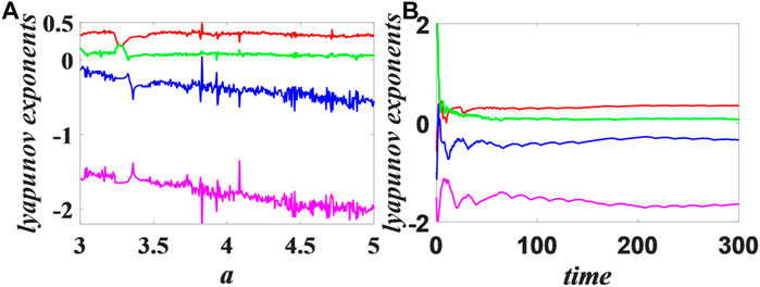
FIGURE 1. Eq. 1 sets the parameters as
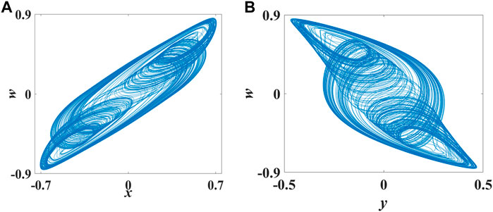
FIGURE 2. Phase diagram of the Hopfield neural network chaotic system. (A)
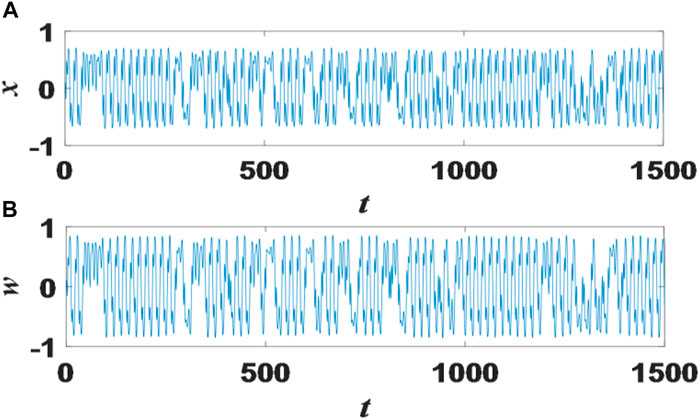
FIGURE 3. Display the time series diagram of state variables x and w. (A) the time series of state variables x(B) the time series of state variables w.
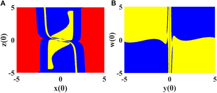
FIGURE 4. The basin of attraction on the plane: (A) is the basin of attraction on the
In this paper, a three-neuron Hopfield neural network system with neuron x exposed to electromagnetic radiation is implemented on the Vivado 2018.3 design platform, and the required modules, such as adders, subtractors, multipliers and comparators, are obtained or created using the IP-CORE generator developed for the platform. The source files of the RK4 numerical algorithm and Eq. 1 are constructed using the required modules and Verilog HDL hardware language under IEEE 754-1985 high precision 32-bit floating point standard. The flow block diagram of the FPGA-based neural network chaotic oscillator has been shown in Figure 5.
As shown in Figure 5, the Hopfield neural network chaotic oscillator has four input signals and five output signals.
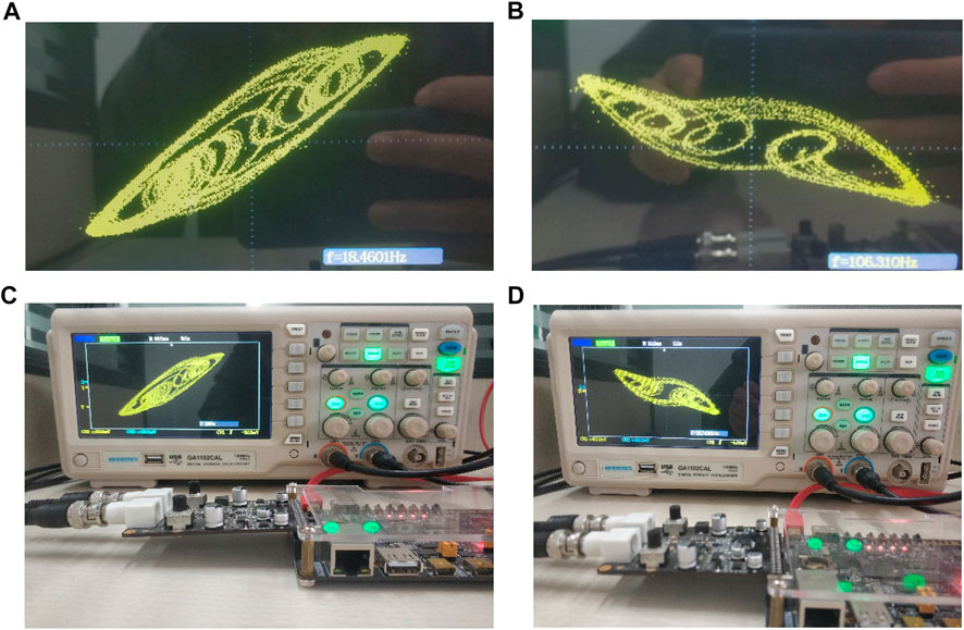
FIGURE 7. The oscilloscope shows the experimental results of (A) FPGA-based
In this part, PRNG based on three-neuron Hopfield neural network with neuron x exposed to electromagnetic radiation is composed of entropy source, feedback controller unit, sampling quantization unit and post-processing unit. The structure of PRNG is shown in Figure 8. In the entropy source unit, the lyapunov exponent of the first dimension of Eq. 1 is the largest, indicating that the sensitivity of neuron x is higher, and the change of neuron x will cause the change of other neurons and the magnetic flux passing through neurons. Therefore, in order to solve the chaotic degradation problem brought by FPGA implementation, the magnetic flux w of neuron x is used as a judgment condition in the feedback controller to selectively interfere with neuron x. The specific steps are as follows.
Step 1. Acquire the 32-bit output signal of the magnetic flux
Step 2. Take the 16th and 17th bit of
The output of the feedback controller is given to the sampling quantization unit and used as the input value of the next iteration of the Hopfield neural network oscillator. By using this feedback controller, the period of the random sequence generated by the PRNG can be greatly extended, and the quality of the pseudo-random sequence can be improved.
In the sampling quantization unit, according to ieee 754-1985 high-precision 32-bit floating-point standard, in each iteration, bits between 0 and 15 are taken from the four output signals
On the Vivado 2018.3 platform, the simulation results of Hopfield neural network based chaotic oscillator PRNG with feedback controller proposed in this paper on FPGA are shown in Figure 10. Completed by Verilog HDL code. According to the implementation time report, FPGA runs at a clock frequency as high as 109.337 MHz, with a minimum running period of 9.146 ns. The data rate of PRNG can reach 16.20 Mbit/s. Table 1 shows the statistics of Xilinx ZYNQ-XC7Z020 chip of PRNG based on FPGA. Finally, the generated bitstream file is output to the oscilloscope, as shown in Figure 11.

FIGURE 10. Behavioral simulation results of the Hopfield neural network oscillator-based PRNG with feedback controller.

TABLE 1. Chip Statistics of PRNG with feedback controller based on Hopfield neural network chaotic oscillator.
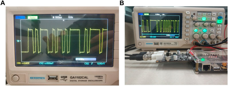
FIGURE 11. (A) Oscilloscope waveform of PRNG based on FPGA implementation; (B) Experimental equipment.
In hardware implementation, chaos degradation caused by calculation accuracy will greatly affect the randomness of PRNG. For example, the short period phenomenon may appear in chaotic simulation, which results in periodicity of random sequence, and finally leads to the failure of random sequence test. At present, NIST 800.22 test suite is the most commonly used randomness test standard, which can use 15 test methods to evaluate a large number of random sequences. Therefore, to determine the randomness of the PRNG with a feedback controller based on the Hopfield neural network chaotic oscillator, we tested its generated random sequences using the NIST 800.22 test suite. In this paper, the PRNG discarded the first 50,000 bits of the random sequence and put the resulting 100 1-MIT test random sequences into the NIST 800.22 test suite. The test results of the random sequences generated by the PRNG based on the original Hopfield neural network chaotic oscillator and the random sequence generated by the PRNG based on the Hopfield neural network chaotic oscillator with a feedback controller are shown in Table 2 (a) and (b), respectively. By comparison, three items in the test result (a) show that the p valve is less than 0.01, and when the p valve is within the range of [0.01,1], it means that the test passed. Therefore, three items in (a) failed NIST 800.22 test suite. Test result (b) shows that all 15 tests have passed, and the random sequence has good randomness. It can be seen that the feedback controller can greatly reduce the impact of chaos degradation on random sequences.

TABLE 2. (A) shows the randomness test results of random sequences generated by PRNG based on the original Hopfield neural network chaotic oscillator, and (B) shows the randomness test results of random sequences generated by PRNG with a feedback controller based on the Hopfield neural network chaotic oscillator.
The size of key space is an important index to determine the security of encryption system, and it is very important to choose the right key space. Large key space can improve encryption strength and better resist key analysis. The small key space can not resist exhaustive attack, and the password is easier to be cracked. Usually, when the key space is greater than 2128, the security of the cipher system can be ensured and the exhaustive attack can be resisted. In this paper, the Hopfield neural network chaotic oscillator and a feedback controller are used to construct PRNG. According to the IEEE 745-1985 floating point standard, the system key consists of the initial conditions
It is well known that chaotic systems are very sensitive to parameters and initial conditions. Therefore, the proposed PRNG with feedback controller based on Hopfield neural network chaotic oscillator should maintain the same sensitivity. Key sensitivity test is used to analyze the impact of small changes in initial conditions or parameters on the corresponding output. When PRNG has high sensitivity, small changes in the input will lead to huge differences in the corresponding output. In this test, the initial conditions
1) By modifying the initial condition
2) By changing the parameter
The bit change rate has always been considered as an important index to measure the sensitivity of PRNG. The closer the bit change rate is to 50%, the higher the key sensitivity of PRNG. The formula of the corresponding bit change rate is as follows:
where p and N represent the bit change rate and sequence length,
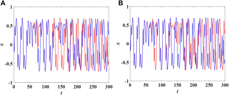
FIGURE 12. (A) is the time domain diagram of neuron x when only initial condition
Auto-correlation and cross-correlation analysis are important methods to detect the correlation between two random sequences of equal length. Among them, auto-correlation is used to detect the random sequence and its shifted sequence, and cross-correlation is used to detect adjacent test random sequences. Now there are two adjacent random sequences
where the correlation coefficient
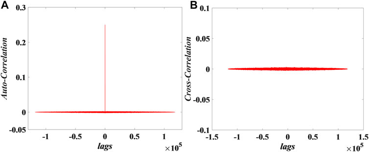
FIGURE 13. Correlation analysis of 15 sequences for PRNG: (A) Auto-correlation, (B) Cross-correlation.
In recent years, image and video encryption based on chaotic system has been widely studied and applied [51–56]. As the main application of chaotic system, PRNG has been paid more and more attention in the field of image encryption [57–59]. At the same time, FPGA also provides strong support for the engineering application of chaotic system [60]. Therefore, as the basis of different engineering applications based on PRNG, FPGA has been paid more and more attention. It is understood that the PRNG with feedback controller based on Hopfield neural network chaotic oscillator proposed in this paper has a complex mathematical model and requires a large amount of chip resources in FPGA implementation. Currently, there is no image encryption system based on this PRNG implemented by FPGA.
In this section, we propose an image encryption system based on the pseudo-random sequences generated by PRNG, and complete the simulation and security analysis on matlab platform. The encryption and decryption scheme of the image encryption system is as follows:
Step 1: A 256 × 256 24-bit depth true color image “Baboon” is selected as the original plaintext image p, and the 256 × 256 24-bit pixels are divided into three 256 × 256 8-bit depth R, G and B pixel channels.
Step 2: The generation of the key sequence used for encryption is consistent with our previous work. In each iteration, a 64-bit random sequence will be generated and the last 8 bits of the random sequence will be kept and added to the key sequence. Finally, three 256 × 256 8-bit key sequences
Step 3: We get the R, G and B pixel channels from step 1 and the key sequence
The experimental results of encrypting the original plaintext image p using key sequences
In this section, we will conduct a security analysis to evaluate the proposed image encryption and decryption system. Security analysis includes histogram analysis, correlation analysis, differential key attack analysis, and entropy analysis. The master key consists of parameters
1) Histogram analysis: The intensity of the distribution of the image pixel values can be known from the histogram. In general, the ideal histogram distribution should be uniform. Therefore, a high-security image encryption and decryption system can make the encrypted image have the ideal histogram distribution. The histograms of the original plaintext image and its R,G and B pixel channels are shown in Figures 15A–D. The histograms of the encrypted image and its
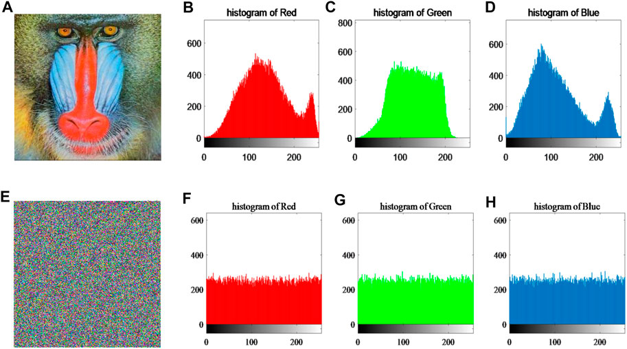
FIGURE 15. The histogram simulation results of the original image and encrypted image. (A) original image; (B), (C) and (D) are histograms of R, G and B pixel channels of the original image, respectively; (E) encrypted image; (F), (G) and (H) are histograms of R, G and B pixel channels of the encrypted image, respectively.
2) Correlation analysis: The quality of the image encryption and decryption system is related to the correlation between adjacent pixels of the encrypted image. The adjacent pixels of the original plaintext image have a high correlation. Therefore, a good image encryption and decryption system can effectively reduce the correlation coefficient between adjacent pixels. In this experiment, we randomly selected 10,000 pairs of adjacent pixels in the horizontal, vertical and diagonal directions to calculate the correlation coefficients of the original plaintext image and the encrypted image. The correlation coefficients can be calculated by Eq. 7, and the results are shown in Table 4. The results show that the system has the ability to resist statistical attacks.
3) Differential key attack analysis: Differential key attack analysis is an important method to evaluate the resistance of image encryption and decryption systems to attacks. Among them, number of pixel change rate (NPCR) and unified average changing intensity (UACI) are used as metrics for the analysis. Suppose we generate two key sequences
Where, N and M denote the number of pixels in the width and length of the encrypted image. The calculation results are shown in Table 5, and the results are ideal.
4) Entropy analysis: Judging the security of an image encryption and decryption system requires the help of information entropy. When the information entropy of an encrypted image is close to 8, we say that it achieves the ideal information entropy and indicates that the encryption and decryption system has good security. The formula for calculating information entropy is as follows.
The results are shown in Table 6, and the entropy value of the encrypted image is close to 8, reaching the ideal information entropy.

TABLE 6. The results of information entropy about R, B, G and total pixel channel of original plaintext image and encrypted image.
In this section, we design and implement a PRNG with a feedback controller image encryption system based on the Hopfield neural network chaotic oscillator on FPGA. All experiments also adopt 32-bit IEEE 754-1985 floating-point standard, design and simulation on Vivado 2018.3 platform using Verilog HDL hardware language and developed IP-core generator, and finally, completed on Xilinx Zynq-XC7Z020 chip. The key sequence generation and image encryption and decryption processes are consistent with the simulation process. Figure 16. is the flow chart of implementing PRNG based image encryption system on FPGA. As shown in Figure 16, the image encryption system on FPGA consists of four parts: chip data RAM, the key sequence, data encryption module and VGA display controller. Where the image data and random sequence accessed in the chip are provided by the software Image2Lcd and the PRNG proposed in this paper, respectively. The encrypted image data will be stored in the chip and processed with the random sequence again. The image decryption system consists of three modules: the key sequence, the data decryption module and the VGA display controller. In this experiment, the Image2Lcd software is used to divide the 256 × 256 24-bit depth true color image “Baboon” into three 256 × 256 8-bit data and store them in the chip data RAM. In the data encryption module, the image data is XORed with the random sequence, and the calculated data is transmitted to the display through the VGA display controller to complete the image encryption. Figure 17. shows the experimental results based on FPGA. As shown in Figure 17A, the encrypted image is obtained by processing the data of the original image and the key sequence. Figure 17B shows that when the encrypted image data is processed with the correct key sequence, the original image before encryption can be obtained. The experimental results verify the value of the proposed PRNG in engineering application.
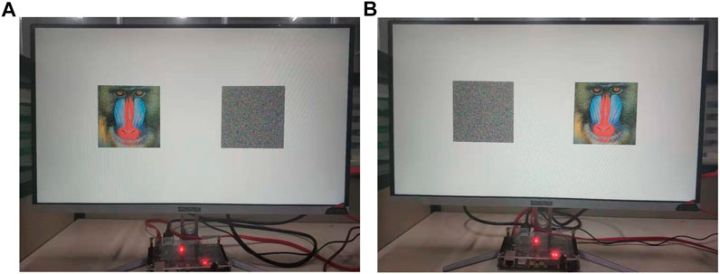
FIGURE 17. The results of image encryption and decryption based on PRNG with feedback controller. (A) the original and encrypted image on the FPGA. (B) the encrypted and decrypted image on the FPGA.
In this paper, a PRNG with a feedback controller based on the improved Hopfield chaotic neural network oscillator is proposed and well implemented on FPGA. Among them, the magnetic flux of neurons is taken as the judgment condition, and the feedback controller is used to add the corresponding interference factor to the neurons with the highest Lyapunov exponent, so as to reduce the influence of chaos degradation on the generated random numbers and improve the randomness of the random sequence. The post-processing unit consists of 32 registers and 15 XOR comparators. From the chip statistics, it can be seen that the PRNG can be implemented on FPGA and the output data rate can be up to 16.2 Mbit/s. The performance of the PRNG was tested. The security analysis and FPGA implementation of the image encryption and decryption system based on PRNG show that PRNG has good randomness and engineering application value. Existing feedback controllers and post-processing algorithms will be improved in the future to further improve the randomness of the PRNG and reduce the impact of chaotic degradation.
The raw data supporting the conclusion of this article will be made available by the authors, without undue reservation.
All authors listed have made substantial, direct, and intellectual contribution to the work and approved it for publication.
This work was supported by the National Natural Science Foundation of China under Grants No. 61504013 and 61702052, and by the Natural Science Foundation of Hunan Province under Grants No. 2019JJ50648, 2020JJ4622, and 2020JJ4221, and by Guangxi Key Laboratory of Cryptography and Information Security under Grant No. GCIS201919, and by the Postgraduate Training Innovation Base Construction Project of Hunan Province under Grant No. 2020-172-48, and the Postgraduate Scientic Research Innovation Project of Hunan Province under Grant No. CX20200884, and by the Scientific Research Fund of Hunan Provincial Education Department under grant no. 18A137, and by the young teacher development program project of Changsha university of science and technology under grant 2019QJCZ013, and by the special funds for the construction of innovative provinces in Hunan Province under grant 2020JK4046.
The authors declare that the research was conducted in the absence of any commercial or financial relationships that could be construed as a potential conflict of interest.
1. Zhong S. Heterogeneous Memristive Models Design and its Application in Information Security. Computer Mater Continua (2019) 60(2):465–79. doi:10.32604/cmc.2019.05853
2. Zuo J, Lu Y, Gao H, Cao R, Guo Z, Feng J. Comprehensive Information Security Evaluation Model Based on Multi-Level Decomposition Feedback for Iot. Comp Mater Continua (2020) 65(1):683–704. doi:10.32604/cmc.2020.010793
3. Fang Z, Cai J, Tian L. Security of Chip Bank Card in Remote Payment Based on Risk Feature. Comp Syst Sci Eng (2020) 35(4):299–305. doi:10.32604/csse.2020.35.299
4. Du Z. Personal Data Security and Supervision in the Age of Large Data. Intell Automation Soft Comput (2019) 25(4):847–53.
5. Centonze P. Security and Privacy Frameworks for Access Control Big Data Systems. Comp Mater Continua (2019) 59(2):361–74. doi:10.32604/cmc.2019.06223
6. Gu K, Wu N, Yin B, Jia WSecure Data Query Framework for Cloud and Fog Computing. IEEE Trans Netw Serv Manag (2019) 17(1):332–45.
7. Han W, Tian Z, Huang Z, Zhong L, Jia Y. System Architecture and Key Technologies of Network Security Situation Awareness System Yhsas. Comp Mater Continua (2019) 59(1):167–80. doi:10.32604/cmc.2019.05192
8. You I, Choi C, Sharma V, Woungang V, Bhargava I, Bharat K Guest Editorial: Advances in Security and Privacy Technologies for Forthcoming Smart Systems, Services, Computing, and Networks. Intell Automation Soft Comput (2019) 25(1):117–9.
9. Kelec A, Djuric Z. A Proposal for Addressing Security Issues Related to Dynamic Code Loading on Android Platform. Comp Syst Sci Eng (2020) 35(4):271–82. doi:10.32604/csse.2020.35.271
10. Zhang Q, Liang Z, Cai Z. Developing a New Security Framework for Bluetooth Low Energy Devices. Comput Mater Continua (2019) 59(2):457–71. doi:10.32604/cmc.2019.03758
11. Yu F, Qian S, Chen X, Huang S, Cai Y, Jin S, et al. Chaos-based Engineering Applications with a 6d Memristive Multistable Hyperchaotic System and a 2d Sf-Simm Hyperchaotic Map. Complexity (2021) 2021:6683284. doi:10.1155/2021/6683284
12. Murillo-Escobar MA, Cruz-Hernández C, Cardoza-Avendaño L, Méndez-Ramírez R. A Novel Pseudorandom Number Generator Based on Pseudorandomly Enhanced Logistic Map. Nonlinear Dyn (2017) 87(1):407–25. doi:10.1007/s11071-016-3051-3
13. Deng Q, Wang C, Yang L. Four-wing Hidden Attractors with One Stable Equilibrium point. Int J Bifurcation Chaos (2020) 30(06):2050086. doi:10.1142/s0218127420500868
14. Yu F, Shen H, Zhang Z, Huang Y, Cai S, Du S. A New Multi-Scroll Chua's Circuit with Composite Hyperbolic tangent-cubic Nonlinearity: Complex Dynamics, Hardware Implementation and Image Encryption Application. Integration (2021), 2021 in press.
15. Yang F, Mou J, Ma C, Cao Y. Dynamic Analysis of an Improper Fractional-Order Laser Chaotic System and its Image Encryption Application. Opt lasers Eng (2020) 129:106031. doi:10.1016/j.optlaseng.2020.106031
16. Yu F, Shen H, Liu L, Zinan Z, Yuanyuan H, Binyong H, et al. “Ccii and Fpga Realization: A Multistable Modified Fourth-Order Autonomous Chua’s Chaotic System with Coexisting Multiple Attractors. Complexity (2020) 2020:5212601. doi:10.1155/2020/5212601
17. Wan Q, Zhou Z, Ji W, Wang C, Yu F, et al. Dynamic Analysis and Circuit Realization of a Novel No-Equilibrium 5d Memristive Hyperchaotic System with Hidden Extreme Multistability. Complexity (2020) 2020:7106841. doi:10.1155/2020/7106861
18. Wen Z, Li Z, Li X. Bursting Dynamics in Parametrically Driven Memristive Jerk System. Chin J Phys (2020) 66:327–34. doi:10.1016/j.cjph.2020.04.009
19. Yao W, Wang C, Sun Y, Yao W (2020). Robust Multimode Function Synchronization of Memristive Neural Networks with Parameter Perturbations and Time-Varying Delays. IEEE Trans Syst Man, Cybernetics: Syst. doi:10.1109/TSMC.2020.2997930
20. Zhou C, Wang C, Sun Y, et al. Weighted Sum Synchronization of Memristive Coupled Neural Networks. Neurocomputing (2020) 403:225–32. doi:10.1016/j.neucom.2020.04.087
21. Yu F, Qian S, Chen X, Huang Y, Liu L, Shi C, et al. A New 4d Four-wing Memristive Hyperchaotic System: Dynamical Analysis, Electronic Circuit Design, Shape Synchronization and Secure Communication. Int J Bifurcation Chaos (2020) 30(10):2050147. doi:10.1142/s0218127420501473
22. Li Y, Li Z, Ma M, Wang M. Generation of Grid Multi-wing Chaotic Attractors and its Application in Video Secure Communication System. Multimedia Tools Appl (2020) 79:29161–77. doi:10.1007/s11042-020-09448-7
23. Xiu C, Zhou R, Zhao S, Xu G. Memristive Hyperchaos Secure Communication Based on Sliding Mode Control. Nonlinear Dyn (2021) 104:789–805. doi:10.1007/s11071-021-06302-9
24. Lin H, Wang C. Influences of Electromagnetic Radiation Distribution on Chaotic Dynamics of a Neural Network. Appl Math Comput (2020) 369:124840. doi:10.1016/j.amc.2019.124840
25. Yao W, Wang C, Cao J, Sun Y, Zhou C. Hybrid Multisynchronization of Coupled Multistable Memristive Neural Networks with Time Delays. Neurocomputing (2019) 363:281–94. doi:10.1016/j.neucom.2019.07.014
26. Yu F, Liu L, Xiao L, Li K, Cai S. A Robust and Fixed-Time Zeroing Neural Dynamics for Computing Time-Variant Nonlinear Equation Using a Novel Nonlinear Activation Function. Neurocomputing (2019) 350:108–16. doi:10.1016/j.neucom.2019.03.053
27. Yao W, Wang C, Sun Y, Zhou C, Lin H. Synchronization of Inertial Memristive Neural Networks with Time-Varying Delays via Static or Dynamic Event-Triggered Control. Neurocomputing (2020) 404:367–80. doi:10.1016/j.neucom.2020.04.099
28. Xu Q, Tan X, Zhu D, Bao H, Hu Y, Bao B. Bifurcations to Bursting and Spiking in the Chay Neuron and Their Validation in a Digital Circuit. Chaos, Solitons & Fractals (2020) 141:110353. doi:10.1016/j.chaos.2020.110353
29. Lin H, Wang C, Tan Y. Hidden Extreme Multistability with Hyperchaos and Transient Chaos in a Hopfield Neural Network Affected by Electromagnetic Radiation. Nonlinear Dyn (2020) 99(3):2369–86. doi:10.1007/s11071-019-05408-5
30. Li Z, Zhou H, Wang M, Ma M Coexisting Firing Patterns and Phase Synchronization in Locally Active Memristor Coupled Neurons with Hr and Fn Models. Nonlinear Dyn (2021) 104, 1455–1473. doi:10.1007/s11071-021-06315-4
31. Wang F, Zhang L, Zhou S, Huang Y. Neural Network-Based Finite-Time Control of Quantized Stochastic Nonlinear Systems. Neurocomputing (2019) 362:195–202. doi:10.1016/j.neucom.2019.06.060
32. Long M, Zeng Y. Detecting Iris Liveness with Batch Normalized Convolutional Neural Network. Comp Mater Continua (2019) 58(2):493–504. doi:10.32604/cmc.2019.04378
33. Yu F, Li L, He B, Liu L, Qian S, Shen H, et al. Pseudorandom Number Generator Based on a 5d Hyperchaotic Four-wing Memristive System and its Fpga Implementation. Eur Phys Journal-Special Top (2021). doi:10.1140/epjs/s11734-021-00132-x
34. Dong L, Yao G. Method for Generating Pseudo Random Numbers Based on Cellular Neural Network. J Commun (2016) 37:85–91.
35. Yu F, Li L, He B, Liu L, Qian S, Huang Y, et al. Design and Fpga Implementation of a Pseudorandom Number Generator Based on a Four-wing Memristive Hyperchaotic System and Bernoulli Map. IEEE Access (2019) 7:181 884–181. doi:10.1109/access.2019.2956573
36. Tuna M. A Novel Secure Chaos-Based Pseudo Random Number Generator Based on Ann-Based Chaotic and Ring Oscillator: Design and its Fpga Implementation. Analog Integr Circ Sig Process (2020) 105(2):167–81. doi:10.1007/s10470-020-01703-z
37. Kawashima I, Morie T, Tamukoh H. Fpga Implementation of Hardware-Oriented Chaotic Boltzmann Machines. IEEE Access (2020) 8:204360–204.
38. Fraga D, Gerardo L, Esteban T, Cuauhtemoc M. Hardware Implementation of Pseudo-random Number Generators Based on Chaotic Maps. Nonlinear Dyn (2017) 90(3):1661–70.
39. Chen X, Qian S, Yu F, Zhang Z, Zinan S, Shen H, et al. Pseudorandom Number Generator Based on Three Kinds of Four-wing Memristive Hyperchaotic System and its Application in Image Encryption. Complexity (2020) 2020:8274685. doi:10.1155/2020/8274685
40. Zhao Y, Gao C, Liu J, Dong S. A Self-Perturbed Pseudo-random Sequence Generator Based on Hyperchaos. Chaos, Solitons & Fractals: X (2019) 4:100023. doi:10.1016/j.csfx.2020.100023
41. Singh JP, Pham VT, Hayat T, Jafari S, Alsaadi FE, Roy BK. A New Four-Dimensional Hyperjerk System with Stable Equilibrium point, Circuit Implementation, and its Synchronization by Using an Adaptive Integrator Backstepping Control. Chin Phys. B (2018) 27(10):100501. doi:10.1088/1674-1056/27/10/100501
42. Liu Y, Tong X. Hyperchaotic System‐based Pseudorandom Number Generator. IET Inf Security (2016) 10(6):433–41. doi:10.1049/iet-ifs.2015.0024
43. Wang J, Chen Z, Yuan Z. The Generation of a Hyperchaotic System Based on a Three-Dimensional Autonomous Chaotic System. Chin Phys B (2006) 15(6):1216.
44. Singh JP, Roy BK. Simplest Hyperchaotic System with Only One Piecewise Linear Term. Electron Lett (2019) 55(7):378–80. doi:10.1049/el.2018.8078
45. Lin H, Wang C, Yao W, Tan Y. Chaotic Dynamics in a Neural Network with Different Types of External Stimuli. Commun Nonlinear Sci Numer Simulation (2020) 90:105390. doi:10.1016/j.cnsns.2020.105390
46. Lin H, Wang C, Hong Q, Sun Y. A Multi-Stable Memristor and its Application in a Neural Network. IEEE Trans Circuits Syst (2020) 67(12):3472–6. doi:10.1109/tcsii.2020.3000492
47. Cui L, Chen C, Jin J. Dynamic Analysis and Fpga Implementation of New Chaotic Neural Network and Optimization of Traveling Salesman Problem. Complexity (2021) 2021:5521192. doi:10.1155/2021/5521192
48. Yu F, Shen H, Zhang Z, Huang Y, Cai S, Du S. Dynamics Analysis, Hardware Realization and Engineering Applications of Novel Multi-style Attractors in a Neural Network Under Electromagnetic Radiation. Chin Phys. B (2021), 2021 in press.
49. Kwan HK. Simple Sigmoid-like Activation Function Suitable for Digital Hardware Implementation. Electron Lett (1992) 28(15):1379–80. doi:10.1049/el:19920877
50. Liu Z, Wang Xa., Sun and Ken Lu C, Lu K. Implementation System of Human Eye Tracking Algorithm Based on Fpga. Comp Mater Continua (2019) 58(3):653–64. doi:10.32604/cmc.2019.04597
51. Lu B, Liu F, Ge X, Li Z. Cryptanalysis and Improvement of a Chaotic Map-Control-Based and the plain Image-Related Cryptosystem. Comput Mater Continua (2019) 61(2):687–99. doi:10.32604/cmc.2019.05633
52. Liu J, Li J, Cheng J, Ma J, Sadiq N, Han B, et al. A Novel Robust Watermarking Algorithm for Encrypted Medical Image Based on Dtcwt-Dct and Chaotic Map. Comput Mater Continua (2019) 61(2):889–910. doi:10.32604/cmc.2019.06034
53. Cheng G, Wang C, Xu C. A Novel Hyper-Chaotic Image Encryption Scheme Based on Quantum Genetic Algorithm and Compressive Sensing. Multimedia Tools Appl (2020) 79(39–40):29 243–29. doi:10.1007/s11042-020-09542-w
54. Li X, Mou J, Xiong L, Wang Z, Xu J. Fractional-order Double-ring Erbium-doped Fiber Laser Chaotic System and Its Application on Image Encryption. Opt Laser Tech (2021) 140:107074. doi:10.1016/j.optlastec.2021.107074
55. Zeng J, Wang C. A Novel Hyperchaotic Image Encryption System Based on Particle Swarm Optimization Algorithm and Cellular Automata. Security Commun Networks (2021) 2021:6675565. doi:10.1155/2021/6675565
56. Wang X, Chen S, Zhang Y. A Chaotic Image Encryption Algorithm Based on Random Dynamic Mixing. Opt Laser Tech (2021) 138:106837. doi:10.1016/j.optlastec.2020.106837
57. Yu F, Liu L, Qian S, Li L, Huang Y, Shi C, et al. Chaos-based Application of a Novel Multistable 5d Memristive Hyperchaotic System with Coexisting Multiple Attractors. Complexity (2020) 2020:8034196. doi:10.1155/2020/8034196
58. Sun J, Peng M, Liu F, Tang C. Protecting Compressive Ghost Imaging with Hyperchaotic System and Dna Encoding. Complexity (2020) 2020:8815315. doi:10.1155/2020/8815315
59. Deng J, Zhou M, Wang C, Wang S, Xu C. Image Segmentation Encryption Algorithm with Chaotic Sequence Generation Participated by Cipher and Multi-Feedback Loops. Multimedia Tools Appl (2021) 80:13821–13.
Keywords: PRNG, hopfield neural network, electromagnetic radiation, chaotic degradation, FPGA, security analysis, image encryption and decryption system
Citation: Yu F, Zhang Z, Shen H, Huang Y, Cai S, Jin J and Du S (2021) Design and FPGA Implementation of a Pseudo-random Number Generator Based on a Hopfield Neural Network Under Electromagnetic Radiation. Front. Phys. 9:690651. doi: 10.3389/fphy.2021.690651
Received: 03 April 2021; Accepted: 14 May 2021;
Published: 04 June 2021.
Edited by:
Viet-Thanh Pham, Phenikaa University, VietnamReviewed by:
Shaobo He, Central South University, ChinaCopyright © 2021 Yu, Zhang, Shen, Huang, Cai, Jin and Du. This is an open-access article distributed under the terms of the Creative Commons Attribution License (CC BY). The use, distribution or reproduction in other forums is permitted, provided the original author(s) and the copyright owner(s) are credited and that the original publication in this journal is cited, in accordance with accepted academic practice. No use, distribution or reproduction is permitted which does not comply with these terms.
*Correspondence: Fei Yu, eXVmZWl5ZnlmQGNzdXN0LmVkdS5jbg==
Disclaimer: All claims expressed in this article are solely those of the authors and do not necessarily represent those of their affiliated organizations, or those of the publisher, the editors and the reviewers. Any product that may be evaluated in this article or claim that may be made by its manufacturer is not guaranteed or endorsed by the publisher.
Research integrity at Frontiers

Learn more about the work of our research integrity team to safeguard the quality of each article we publish.