 Yu Tian1
 Fang-Fang Ren
 Qingguo Du
- 1School of Information Engineering, Wuhan University of Technology, Wuhan, China
- 2Research Institute of Shenzhen, Nanjing University, Shenzhen, China
- 3School of Electronic Science and Engineering, Nanjing, China
- 4National Engineering Laboratory for Fiber Sensing Technology, Wuhan University of Technology, Wuhan, China
- 5State Key Laboratory of Silicate Materials for Architectures, Wuhan University of Technology, Wuhan, China
Designing and fabricating high-performance polarization converters that exhibit asymmetric transmission (AT), for light with different circularly/linearly polarized states with opposite propagating directions, are in high demand. The AT phenomenon leads to potential applications as isolators and circulators in information and communication systems. We propose a chiral metamaterial structure with high AT efficiency for two types of linearly orthogonal polarized red-near-IR light in two opposite incident directions. Theoretical results showed that the proposed chiral metamaterial structure achieves cross-polarization conversion where the polarization conversion ratio (PCR) is over 90%, in a broadband wavelength range from 715 to 810 nm, for both forward-propagating linearly polarized light and backward-propagating orthogonal linearly polarized light. The physical mechanisms of the polarization converter with the AT have been investigated. It was confirmed that the Fabry–Perot-like resonance and coupling between electric and magnetic dipoles lead to highly efficient asymmetric polarization conversion for two orthogonal linearly polarized light. Additionally, the conversion efficiency and bandwidth of the polarization converter are successfully optimized by adjusting the related structure parameters.
Introduction
The asymmetric transmission (AT) phenomenon arises from reversed polarization conversion efficiencies for light with different circularly/linearly polarized states propagating from opposite directions. The AT phenomenon leads to potential applications as isolators and circulators in information and communication systems. Traditionally, AT is achieved by the Faraday magneto-optical effect of magnetic materials. However, devices with magnetic materials are usually bulky and heavy, which makes them unsuitable for micro, terahertz (THz), and optical wave applications.
Over the past decades, metamaterials, artificial composite materials, provide a variety of opportunities to control the amplitude, phase, and polarization of light in an arbitrary manner [1]. Chirality in metamaterials, providing a convenient way to control the polarization state of light, has attracted much attention from scientists in the research field [2]. So far, chiral metamaterials have been demonstrated to possess giant gyrotropy [3, 4], high circular dichroism [5, 6], and strong optical activity [7, 8]. Based on the remarkable effect of circular conversion dichroism, it is potentially possible to make a compact and efficient AT polarization converter [9–11]. Recently, great efforts have been made to achieve the AT effect for linearly polarized waves in the THz region with chiral metamaterials [12–16]. Dai et al. realized the AT effect for linearly polarized waves in the THz region with a chiral metamaterial structure consisting of two double-T structures, where the AT parameter (the difference between the total transmitted intensities for different propagation directions) remains higher than 0.35 in 1.38–1.63 THz [17]. Cheng et al. presented a photo-excited complementary chiral metamaterial, in which the polarization conversion ratio (PCR) is over 90% in the frequency range of 0.69–0.82 THz [18]. In recent years, dielectric metasurfaces exhibit an efficient approach to control electromagnetic waves from visible to THz ranges. Wang et al. theoretically propose and experimentally validate the manipulation of symmetry-assisted spectral line shapes in the dielectric double-Fano metasurfaces, which can support two kinds of channels: multipole localized resonance modes and a propagating continuum mode [19]. They also demonstrate highly efficient THz waveplates via all-dielectric metamaterials. Compared with metallic counterparts, dielectric metamaterials are free of intrinsic ohmic losses, which naturally enable Electromagnetic (EM) wave controls with high efficiencies [20]. With the development of micro–nano processing technology, researches of metamaterials have further extended the working wavelength to the visible wavelength region, which provides a good opportunity to design and develop high-performance visible/near-IR AT metamaterial devices [21].
In this study, we propose a polarization converter with AT effect for linearly polarized red-near-IR light based on a chiral metamaterial structure. Theoretical results showed that the metamaterial structure preserves efficient polarization conversion for one forward-propagating linearly polarized light and one backward-propagating orthogonal linearly polarized light. The PCR is over 90% in a broadband wavelength range from 715 to 810 nm. With numerical simulations, we have investigated the mechanisms of AT and asymmetric polarization conversion for two types of orthogonal linearly polarized light. Finally, the surface current distributions are obtained to provide an intuitive picture of the coupling between incident light and the metamaterial structure at the resonant frequency.
Device Structure and Methodology
A three-dimensional (3D) schematic illustration of the unit cell of the proposed chiral metamaterial structure is shown in Figure 1A, which consists of a double-rod resonator sandwiched between an arrow structure and a cut-wire structure. The tri-layered metamaterial structures are separated by two layers of dielectric material. Figures 1B–D shows the front views of the arrow structure, the double-rod resonator, and the cut-wire structure. As shown in Figure 1B, the lengths of two sides of the arrow are indicated with w1 and w2, the width of the arrow is l1, and the length and width of the arrow shaft are indicated as w3 and l2, respectively. The unit of cell width in x and y directions is indicated as ax and ay, respectively. The width of the symmetric tail of the arrow shaft is indicated as m. The rod width and gap distance between two rods in the double-rod structure are indicated as g1 and g2, respectively, as shown in Figure 1C. The width of the cut-wire is indicated as w4 and the length of the cut-wire is the same as the unit width of ay, as shown in Figure 1D. The layer thickness of arrow structure, double-rod structure, cut-wire structure, and two dielectric inserting layers is indicated as h1, h2, h3, and h4 from left to right, and the layers of the metallic structures are named L1, L2, and L3, respectively, as shown in Figure 1E. To satisfy the demand of AT effect, the ultimate optimized parameters of the metamaterial in the simulation are listed as following: ax = ay = 500 nm, w1 = 445 nm, w2 = 221 nm, w3 = 418 nm, w4 = 130 nm, l1 = 74 nm, l2 = 106 nm, m = 75 nm, g1 = 60 nm, g1 = 240 nm, h1 = 35 nm, h2 = 360 nm, h3 = 260 nm, and h4 = 15 nm. The dielectric interlayers were set as silicon dioxide with a relative permittivity of 2.1 [12]. Gold was chosen as the metal of the metamaterial structure as its effective permittivity could be calculated by a simple Drude model which works well in the visible-IR wavelength range as given in the following Equation [22].
where ωp = 2π × 2.175 × 1015 s−1 and ωc = 2π × 6.5 × 1012 s−1 are plasma frequency and collision frequency, respectively. The numerical simulations were performed with the finite-difference time-domain (FDTD) method. Periodic boundary conditions (PBCs) and perfectly matched layer (PML) boundary conditions were applied to x/y and z-directions, respectively. An overall mesh size of 15 nm was applied to the whole simulation region. To improve the accuracy of the simulation results, a finer mesh grid was applied at the interface between the metal and the dielectric material (10 nm in the x and y directions, and 1 nm in the z-direction). Light was illuminated on the structure from the arrow side along the z-direction.
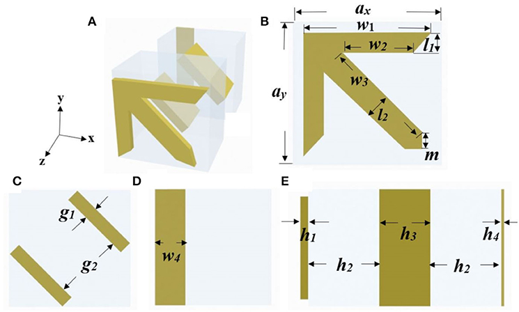
Figure 1. Schematic illustration of the five-layer structure: (A) A three-dimensional (3D) perspective view. (B) The front view of the arrow structure layer. (C) The front view of the double-rod resonator layer. (D) The front view of the cut-wire layer. (E) The stacking scheme of L1, L2, L3, and two insert dielectric layers.
Results And Discussions
To characterize the optical properties of the proposed structure, the moduli of complex Jones matrix are calculated and shown in Figures 2A,B, which represent the co- and cross-polarized transmission coefficients of x and y polarizations for backward (-z) and forward (+z) propagation light, respectively [23]. Here, the subscripts i and j correspond to the polarization states of the transmitted and incident light, which could be either x or y linearly polarized. The superscripts b and f correspond to the backward and forward propagations. and represent co-polarized transmission coefficient where the transmitted light preserves the polarization status of backward/forward incident light, respectively. and represent cross-polarized transmission coefficients where the polarization of transmitted light (y/x polarization) converts to the orthogonal polarization (x/y) of backward/forward propagating light, respectively. As shown in Figures 2A,B, which means that there is no propagating direction dependence for co-polarized transmission of x-polarized light. Similarly, , which indicates that there is no propagation direction dependence for co-polarized transmission of y-polarized light. From Figure 2A, for backward propagating light,is larger than 0.8 for the wavelength range from 733 to 753 nm with a maximum transmission coefficient of 0.82 at the resonant wavelength of 742 nm, while is lower than 0.3 for the same wavelength range. The big difference between and indicates that x-polarized light has been converted to y-polarized light efficiently, and the polarization state of y-polarized light is kept unchanged for backward propagating light. Similarly, as shown in Figure 2B, for forward propagating light, y-polarized light has been converted to x-polarized light, and the polarization state of x-polarized light is kept unchanged. The difference between the cross-polarization transmission coefficients and originates from the asymmetric polarization conversion of the chiral metamaterial structure. These results demonstrate that a polarization converter with AT effect for x- and y-polarized light has been successively achieved.
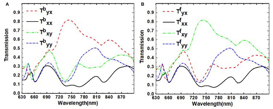
Figure 2. Simulated co- and cross-polarized transmission coefficiency of x- and y- polarizations for (A) backward-propagating (B) forward-propagating light, respectively.
To evaluate the cross-polarization conversion efficiency, the PCR for backward-propagating x-polarized light is calculated and plotted in Figure 3. The PCR is defined as . As shown in Figure 3, the PCR is larger than 90% for the wavelength range from 715 to 810 nm, which means that the x-polarized light can be efficiently converted to the orthogonal y-polarized light. The PCR for forward-propagating y-polarized light (not shown) is the same as that of the backward-propagating x-polarized light. The AT parameter, another important index to evaluate the AT performance of the chiral metamaterial, is defined as for the backward-propagating linearly polarized light. The AT parameter for both x and y-polarized lights are shown in Figure 4. The AT parameter reaches its maximum of 0.508 at the wavelength of 739 nm, which proves the existence of asymmetric polarization conversion for x- and y-polarized light.
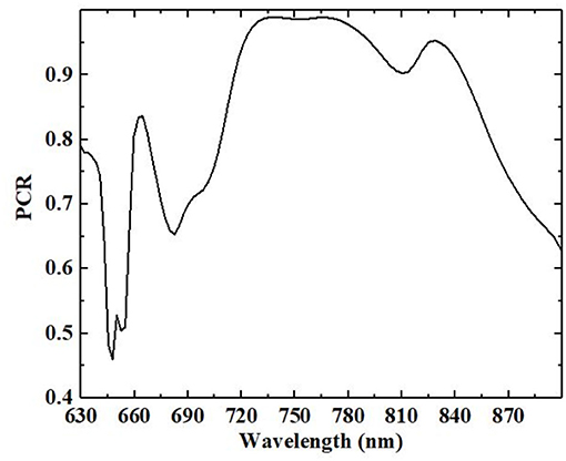
Figure 3. The polarization conversion ratio (PCR) of x-polarized light with backward propagation.
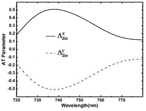
Figure 4. The asymmetric transmission (AT) parameter for backward-propagating light.
To fully understand the function of each layer in the metamaterial structure for asymmetric polarization conversion, we investigate the cross-polarized transmission coefficient of both x- and y-polarized backward incident light for layers of L2, L2L3, and L1L2L3, respectively. When the linearly polarized light passes through the single layer L2, the simulated cross-polarized transmission coefficient spectra are calculated and shown as the dark solid lines in Figures 5A,B, respectively. Since the double-rod resonator has a symmetry plane that is 45° inclined with respect to both x and y axes, the layer of L2 functions as a converter to rotate incident light polarization by 90° [24] and obey the relations of tyx = txy [21]. The polarization rotation can be described as the excitation of an electric dipole momentum P mainly along the double-rod orientation, having both x- and y-components (Px and Py) when the x-polarized light is illuminated on the double-rod resonator [25, 26]. Similar behavior occurs in the case of y-polarized incidence.
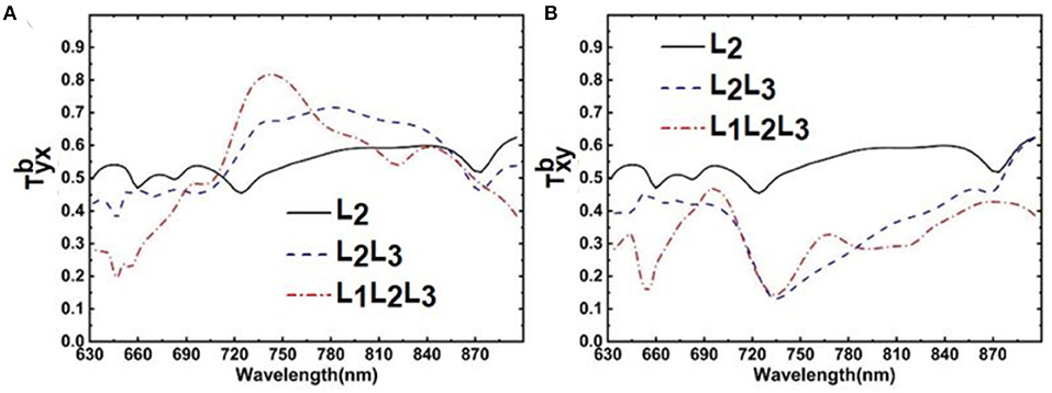
Figure 5. Cross-polarized transmission coefficiency of (A) x-polarized and (B) y-polarized backward propagating light of L2, L2L3, and L1L2L3, respectively.
However, withonly L2, tyx = txy is lower than 0.6 in the full wavelength range studied here, which means that both the AT effect and the cross-polarization conversion efficiency are still insufficient. To improve the conversion efficiency and AT effect, L3 is employed to combine with L2. As shown in Figure 5, after passing through L2L3, tyx ≠ txy anymore as the chiral structures, which consist of L2 and L3 layers, are lacking any symmetry in light propagating direction. It is evident that tyx is largely enhanced with a maximum transmittance of 0.72 at 781 nm, while the value of txy is tremendously suppressed with a minimum transmission coefficient approaching 0.13 at 736 nm. The results show a large difference between tyx and txy due to the addition of L3, as it breaks the remaining mirror symmetry of the metamaterials in the propagation direction (z-axis) and leads to AT effect for linearly polarized light. In this case, the eigenstates are simply elliptical, where no principle rotation direction is assignable [21].
To further improve the AT effect and the cross-polarization conversion efficiency, one additional layer of arrow structure L1 is added on the top of L2L3 layers. As shown in Figure 5A, tyx, after passing through L1L2L3, is higher than 0.8 in the wavelength range from 734 to 752 nm with a maximum transmittance of 0.82 at 742 nm. Simultaneously, as shown in Figure 5B, txy for L1L2L3 is slightly increased with a minimum transmission coefficient of 0.14 at 732 nm. These results indicate an effectively asymmetrical polarization rotation of linearly polarized light from x to y polarization, but not vice versa. We believe that, by introducing the L1 layer, the light is reflected back and forth between the two metallic layers (L1, L2 or L2, L3), which is the so-called Fabry–Perot-like resonance, and, finally, results in enhanced AT effect and asymmetric polarization conversion [27].
To realize the controllable resonant frequency of the designed structure, the influence of structure parameters, such as the rod width and gap distance between two rods in double-rod structure (g1 and g2), the layer thickness (h1, h3, and h4), and the dielectric thickness (h2) of the metamaterial structure on the cross-polarized transmission spectra of the x-polarized backward incident light , has been investigated by using numerical simulations. As shown in Figures 6A–E, the parameters of g1, g2, h1, h3, and h4 had obvious effects on the transmission coefficient but had less effect on the resonant frequency. It is worth noting that, as shown in Figure 6F, dielectric thickness (h2) has an obvious influence on the resonant frequency. The resonant frequency redshifts with the increase of h2 from 330 to 390 nm, which verifies the forming of the Fabry–Perot-like resonance between L1, L2, and L2, L3, where the resonant frequency is determined by the cavity length of the Fabry–Perot-like cavity.
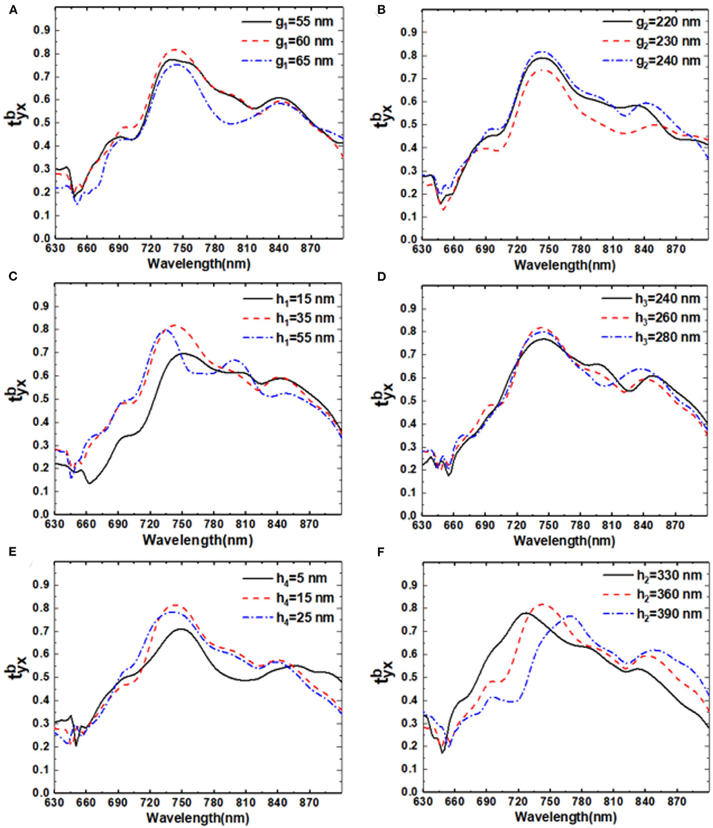
Figure 6. Parameters influence of (A) g1, (B) g2, (C) h1, (D) h3, (E) h4, and (F) h2 on the cross-polarized transmission coefficiency of backward propagating x-polarized light.
To evaluate the performance of the designed chiral structure, we calculated the polarization azimuth angle θ and ellipticity angle η, which are defined as follows: [28].
In the equations, the circular transmission coefficients t++/−− can be obtained from the linear polarization transmission coefficients by t++/−− = txx ± ityx. As shown in Figure 7, there exists a broad wavelength range (724–768 nm) of incident x-polarized light whose polarization azimuth angle θ is around −90° which means that the polarization state has been rotated for −90°. Meanwhile, the ellipticity angle η is around 0° in this range (730–760 nm) which means that there is a pure linear polarization at the resonance wavelength. Both the ellipticity angle η and the polarization azimuth angle θ verify that the backward incident x-polarized light is successfully converted to its cross-polarized transmittance (y-polarized light) after −90° rotation [29].
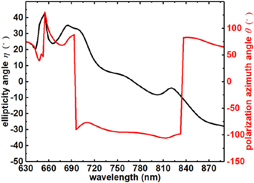
Figure 7. The polarization azimuth angle θ (black line) and ellipticity angle η (red line) of x-polarized incident light.
To analyze the mechanism of the asymmetric polarization conversion, we simulated surface current distributions of the top arrow structure layer, the middle double-rod layer, and the bottom cut-wire structure layer at the resonant frequency of 742 nm. Figures 8A–C shows the instantaneous surface current distributions of the top, middle, and bottom layers at the resonant frequency. For x-polarized backward incident light, at the resonant frequency, the instantaneous direction of the current flow in the middle layer shows both parallel and contrary to that in the bottom layer and top arrow layer, which shows that a mixture of an equivalent magnetic resonator and electric dipole is formed [30, 31]. Under the interaction of magnetic dipoles from the top arrow layer, the middle double rod layer, and the bottom cut-wire layer, the chirality of the structure is enhanced due to the cross-coupling of magnetic dipoles. Within the working band, the co-polarized transmission light is mostly suppressed by optimizing the geometrical parameters. Then, the transmitted light is mostly converted to its cross-polarization after passing through the metamaterial structure [32]. Based on classical multipole theory, the transmitted light can be evaluated by the electromagnetic properties of a scatter which is dominated by the electric dipole moment. Via the integral method, the values of Px and Py were calculated at the resonant frequency with x-polarized backward incident light as and . Py > Px means that a large ratio of incident electromagnetic waves has been converted from the original direction (x) to the orthogonal one (y).
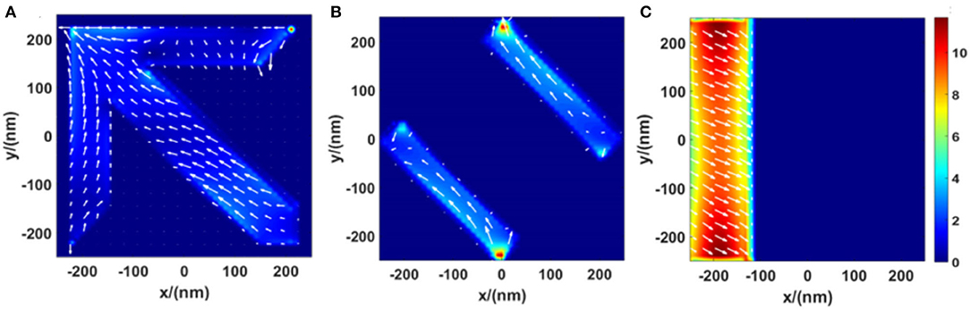
Figure 8. Surface current distributions of (A) the top layer, (B) the bottom layer, and (C) the middle layer for x-polarized incident light at 742 nm. The unit of the current density is 105 A/m.
Conclusion
In summary, we proposed a polarization converter with AT for linearly polarized red-near-IR light based on the chiral metamaterial structure. The structure includes a top arrow layer, a middle double-rod layer, and a bottom cut-wire layer, which are separated by two silicon dioxide dielectric layers. For backward (-z)-propagating x-polarized incident light, high-efficiency cross-polarized transmission is successfully achieved from 734 to 752 nm with a maximum transmission coefficient of 0.82 at 742 nm. Meanwhile, in the same wavelength range, and [[Mathtype-mtef1-eqn-25.mtf]] interchange with each other when the propagation direction of light is reversed. Simulation results show that the double-rod layer itself functions as a polarization conversion layer. With the combination of the double-rod layer and the cut-wire layer, the AT effect and asymmetric polarization conversion are both achieved successfully. By adding the top arrow layer, the efficiency of AT and asymmetric polarization conversion was greatly improved. We also verified that the resonant frequency is mainly determined by the dielectric thickness and that the transmission coefficient is mainly determined by the rod width, gap size, film thickness of the double-rod layer, and the film thicknesses of the arrow layer and the cut-wire layer. Both the ellipticity angle and the polarization azimuth angle verify that the backward x-polarized incident light can be converted into its cross-polarized transmittance. We believe that the designed metamaterial could provide a new route for designing a compact and efficient optical asymmetric polarization converter with AT effect for red-near-IR light.
Data Availability Statement
The original contributions presented in the study are included in the article/supplementary material, further inquiries can be directed to the corresponding author/s.
Author Contributions
YT and ZC performed the simulations and data analysis. YT, ZC, F-FR, and QD wrote the draft and revised the manuscript. F-FR, QD, and ZL gave guidance. QD and ZL supervized the project. All authors contributed to the discussions on this manuscript.
Funding
This work was supported by the National Natural Science Foundation of China (Grant Nos. 62075173 and 91850112) and the Shenzhen Fundamental Research project (Grant No. JCYJ20180307163240991).
Conflict of Interest
The authors declare that the research was conducted in the absence of any commercial or financial relationships that could be construed as a potential conflict of interest.
References
1. Nose T, Sato S, Mizuno K, Bae J, Nozokido T. Refractive index of nematic liquid crystals in the submillimeter wave region. Appl Opt. (1997) 36:6383–7. doi: 10.1364/AO.36.006383
2. Huang Y, Zhou Y, Wu ST. Broadband circular polarizer using stacked chiral polymer films. Opt Express. (2007) 15:6414–9. doi: 10.1364/OE.15.006414
3. Rogacheva V, Fedotov VA, Schwanecke AS, Zheludev NI. Giant gyrotropy due to electromagnetic-field coupling in a bilayered chiral structure. Phys Rev Lett. (2006) 97:177401. doi: 10.1103/PhysRevLett.97.177401
4. Plum E, Fedotov VA, Schwanecke AS, Zheludev NI, Chen Y. Giant optical gyrotropy due to electromagnetic coupling. Appl Phys Lett. (2007) 90:223113. doi: 10.1063/1.2745203
5. Kwon DH, Werner PL, Werner DH. Optical planar chiral metamaterial designs for strong circular dichroism and polarization rotation. Opt Express. (2008) 16:11802–7. doi: 10.1364/OE.16.011802
6. Zhukovsky SV, Novitsky AV, Galynsky VM. Elliptical dichroism: operating principle of planar chiral metamaterials. Opt Lett. (2009) 34:1988–90. doi: 10.1364/OL.34.001988
7. Decker M, Zhao R, Soukoulis CM, Linden S, Wegener M. Twisted split-ring-resonator photonic metamaterial with huge optical activity. Opt Lett. (2010) 35:1593–5. doi: 10.1364/OL.35.001593
8. Ren MX, Plum E, Xu JJ, Zheludev NI. Giant nonlinear optical activity in a plasmonic metamaterial. Nat Commun. (2012) 3:833. doi: 10.1038/ncomms1805
9. Singh R, Plum E, Zhang W, Zheludev NI. Highly tunable optical activity in planar achiral terahertz metamaterials. Opt Express. (2010) 18:13425–30. doi: 10.1364/OE.18.013425
10. Mutlu M, Ozbay E. A transparent 90 degree polarization rotator by combining chirality and electromagnetic wave tunneling. Appl Phys Lett. (2012) 100:051909. doi: 10.1063/1.3682591
11. Ma X, Xiao Z, Liu D. Dual-band cross polarization converter in bi-layered complementary chiral metamaterial. J Mod Opt Lett. (2016) 63:937–40. doi: 10.1080/09500340.2015.1111454
12. Huang C, Feng YJ, Zhao JM, Wang ZB, Jiang T. Asymmetric electromagnetic wave transmission of linear polarization via polarization conversion through chiral metamaterial structures. Phys Rev B Condens Matter Mater Phys. (2012) 85:195131. doi: 10.1103/PhysRevB.85.195131
13. Pan W, Kang Y, Wang C, Tang D, Dong J. All-dielectric metasurface realizing giant asymmetric transmission for linearly polarized wave. Opt Commun. (2018) 407:83–6. doi: 10.1016/j.optcom.2017.08.065
14. Cheng Y, Fan J, Luo H, Chen F, Gong R. Dual-band and high-efficiency circular polarization conversion via asymmetric transmission with anisotropic metamaterial in the terahertz region. Opt Mat Express. (2019) 9:1365–76. doi: 10.1364/OME.9.001365
15. Asgari S, Rahmanzadeh M. Tunable circular conversion dichroism and asymmetric transmission of terahertz graphene metasurface composed of split rings. Opt Commun. (2019) 456:124623. doi: 10.1016/j.optcom.2019.124623
16. Lv T, Chen X, Dong G, Liu M, Shi J. Dual-band dichroic asymmetric transmission of linearly polarized waves in terahertz chiral metamaterial. Nanophotonics. (2007) 90:223113. doi: 10.1515/nanoph-2019-0507
17. Dai LL, Zhang YP, Hara JFO, Zhang HY. Controllable broadband asymmetric transmission of terahertz wave based on Dirac semimetals. Opt Express. (2019) 27:35784–96. doi: 10.1364/OE.27.035784
18. Cheng YH, Luo H, Chen F, Mao XS, Gong RZ. Photo-excited switchable broadband linear polarization conversion via asymmetric transmission with complementary chiral metamaterial for terahertz waves. OSA Continuum. (2019) 2:2391–400. doi: 10.1364/OSAC.2.002391
19. Wang DC, Tang R, Feng Z, Sun S, Xiao S, Tan W. Symmetry-assisted spectral line shapes manipulation in dielectric double-fano metasurfaces. Adv Opt Mater. (2021) 9:2001874. doi: 10.1002/adom.202001874
20. Wang DC, Sun S, Feng Z, Tan W, Qiu CW. Multipolar-interference-assisted terahertz waveplates via all-dielectric metamaterials. Appl Phys Lett. (2018) 113:201103. doi: 10.1063/1.5063603
21. Menzel C, Rockstuhl C, Lederer F. An advanced jones calculus for the classification of periodic metamaterials. Phys Rev A. (2010) 82:053811. doi: 10.1103/PhysRevA.82.053811
22. Yelon A, Piyakis KN, Sacher E. Surface plasmons in drude metals. Surf Sci. (2004) 569:47–55. doi: 10.1016/j.susc.2004.07.028
23. Menzel C, Helgert C, Rockstuhl C, Lederer F. Asymmetric transmission of linearly polarized light at optical metamaterials. Phys Rev Lett. (2010) 104:253902. doi: 10.1103/PhysRevLett.104.253902
24. Wei Z, Huang J, Li J, Xu G, Ju Z. Dual-broadband and near-perfect polarization converter based on anisotropic metasurface. Opt Quant Electron. (2017) 49:298. doi: 10.1007/s11082-017-1121-5
25. Xu WZ, Shi YT, Ye J, Ren FF, Jagadish C. A Terahertz Controlled-NOT Gate Based on Asymmetric Rotation of Polarization in Chiral Metamaterials. Adv. Opt. Mater. (2017) 5:1700108. doi: 10.1002/adom.201700108
26. Xu WZ, Ren FF, Ye J, Lu H, Liang L, Huang X, et al. Electrically tunable terahertz metamaterials with embedded large-area transparent thin-film transistor arrays. Sci Rep. (2016) 6:23486. doi: 10.1038/srep23486
27. Zhou J, Koschny T, Kafesaki M, Economou EN, Pendry JB, Soukoulis CM. Saturation of the magnetic response of split-ring resonators at optical frequencies. Phys Rev Lett. (2005) 95:223902. doi: 10.1103/PhysRevLett.95.223902
28. Xu KK, Xiao ZY, Tang JY. Dual-band asymmetric transmission of both linearly and circularly polarized waves based on chiral meta-surface. Opt Quant Electron. (2016) 48:381. doi: 10.1007/s11082-016-0646-3
29. Li Z, Zhao R, Koschny T, Kafesaki M, Alici KB, Colak E. Chiral metamaterials with negative refractive index based on four “U” split ring resonators. Appl Phys Lett. (2010) 97:81901. doi: 10.1063/1.3457448
30. Wang BX. Quad-Band terahertz metamaterial absorber based on the combining of the dipole and quadrupole resonances of two SRRs. IEEE J Sel Top Quant. (2017) 23:1. doi: 10.1109/JSTQE.2016.2547325
31. Hentschel M, Weiss T, Bagheri S, Giessen H. Babinet to the half: coupling of solid and inverse plasmonic structures. Nano Lett. (2013) 13:4428. doi: 10.1021/nl402269h
Keywords: chiral metamaterial, asymmetric transmission, polarization conversion, dipoles, red-near-infrared
Citation: Tian Y, Chen Z, Ren F-F, Du Q and Li Z (2021) High-Efficiency Asymmetric Transmission of Red-Near-Infrared Light Based on Chiral Metamaterial. Front. Phys. 9:676840. doi: 10.3389/fphy.2021.676840
Received: 06 March 2021; Accepted: 26 April 2021;
Published: 21 May 2021.
Edited by:
Song Sun, China Academy of Engineering Physics, ChinaReviewed by:
Dacheng Wang, China Academy of Engineering Physics, ChinaMing Kang, Tianjin Normal University, China
Copyright © 2021 Tian, Chen, Ren, Du and Li. This is an open-access article distributed under the terms of the Creative Commons Attribution License (CC BY). The use, distribution or reproduction in other forums is permitted, provided the original author(s) and the copyright owner(s) are credited and that the original publication in this journal is cited, in accordance with accepted academic practice. No use, distribution or reproduction is permitted which does not comply with these terms.
*Correspondence: Fang-Fang Ren, ZmZyZW5Abmp1LmVkdS5jbg==; Qingguo Du, cWluZ2d1by5kdUB3aHV0LmVkdS5jbg==; Zhengying Li, emh5bGlAd2h1dC5lZHUuY24=