
94% of researchers rate our articles as excellent or good
Learn more about the work of our research integrity team to safeguard the quality of each article we publish.
Find out more
ORIGINAL RESEARCH article
Front. Phys., 15 June 2021
Sec. Medical Physics and Imaging
Volume 9 - 2021 | https://doi.org/10.3389/fphy.2021.675509
This article is part of the Research TopicInnovations in MR Hardware from Ultra-Low to Ultra-High FieldView all 14 articles
Shortened dipole antennas based on rectangular dielectric blocks play an important role in ultrahigh field magnetic resonance imaging (UHF-MRI) radio frequency (RF) coil design. However, the generally assumed direct contact with the subject is difficult to maintain in typical in vivo settings. We have previously observed that certain dielectrically shortened dipole antennas can produce a substantially altered transmit field distribution with a very low transmit efficiency when the block and the sample are physically separated. Therefore, the aim of this study was to determine a) why certain designs of dielectrically shortened dipole antennas can produce an inefficient transmit field when the block and the sample are physically separated and b) how this depends on key parameters such as rectangular block geometry, dielectric constant, loading geometry, and RF feeding. In this work, two main types of quasi-transverse dielectric modes were found in different rectangular block geometries and interpreted as
Ultrahigh field magnetic resonance imaging (UHF-MRI) in humans (magnetic field strength B0 ≧ 7 T) can be challenging due to the short wavelength (about 12 cm) and increased radio frequency (RF) power deposition in the tissue [1]. Multichannel RF coil arrays, which are widely used to address these issues, allow for transmit field (B1+) shimming to optimize the B1+ homogeneity, thereby providing significant signal-to-noise ratio (SNR) gains and higher acceleration factors in parallel MRI [2–5]. Such multichannel arrays are typically built with loop elements. However, in recent years, it has been shown that dipole antennas can lead to significant B1+ efficiency gains in deeper anatomical regions [6–9], and they also support curl-free current patterns that are crucial to approach the ultimate intrinsic SNR in UHF-MRI [10]. Increasing the number of channels in dipole antenna arrays requires modification to the single dipole antenna element geometry because the length of dipole antennas in free space (∼50 cm at 297.2 MHz) is not suitable for most in vivo MR applications.
Since the wavelength is inversely proportional to the square root of dielectric permittivity εr, one promising approach to shorten dipole antennas is to use a high εr medium [6, 11–13]. Unfortunately, the dimensions of dielectric blocks used in previous investigations were rather large, which made it difficult to use them as building blocks in very large dipole antenna arrays (e.g., 32, 64, or 128 elements). Most of the studies followed what Raaijmakers et al. suggested in their study [6], that is, the height should be at least ¼ of wavelength λ. Later, Ipek et al. [14] found that the optimal transmit field efficiency can be achieved for a block with 150 mm × 50 mm × 50 mm and εr between 90 and 110. Recently, Eigentler et al. [15] developed a self-grounded bowtie antenna, which was immersed in a small volume filled with deuterium oxide (D2O), but they used quite a large water bolus to ensure a direct contact with a cuboid phantom.
All these reports [6, 13–15] assumed there was a direct contact between the dielectric block and the human body (or a phantom with a flat surface). Yet, such a contact is rather difficult to achieve for a solid, rectangular geometry, and it may not always be feasible in clinical settings. The curvature of the human head, for example, makes meeting this condition particularly difficult. Therefore, it is reasonable to assume that the dielectric block and various anatomical structures are physically separated. A detailed study, dedicated to this particular, realistic scenario, has not been conducted yet.
In a previous study, we observed that certain types of dielectrically shortened dipole antennas produced an efficient transmit field in the presence of a small air gap, while others did not [16]. We hypothesized that different dielectric modes can be induced within the rectangular block, thereby affecting the antenna performance; if a rectangular dielectric block is sufficiently large, dielectrically shortened dipole antennas can be interpreted as dipole-fed rectangular dielectric resonator antennas. Rectangular dielectric resonator antennas can be characterized by quasi-transverse electric modes [17–20], and UHF-MRI can be an excellent tool to visualize them if water is used as the dielectric medium [21, 22].
Therefore, the aim of this study was to determine: a) why certain dipole-fed dielectric resonator antennas preserve (and others do not) the transmit field distribution and efficiency when the block and the object are physically separated, b) which parameters play a critical role in this context, and c) to what extent different quasi-transverse electric modes can influence in vivo human MRI at 7 T.
Numerical electromagnetic field and specific absorption rate (SAR) simulations were performed using the finite-difference time-domain solver of Sim4Life (Sim4Life, Zurich, Switzerland). Copper elements were modeled as perfect electrical conductors. The excitation signal was of Gaussian type (center frequency = 297.2 MHz and bandwidth = 300 MHz). The grid was manually adjusted for all the components in the simulation. For conductors, dielectric blocks and ports, the smallest mesh cell was 2 mm (1 mm when the effect of the block/phantom physical separation was investigated; 0.2 mm for 0.5 mm gap for εr = 200), while for the phantoms it was 4 mm. The RF shield in the magnet and polymethylmethacrylate (PMMA) boxes were not included in the simulations. Two types of phantoms were used in the electromagnetic field simulations: a spherical one, which mimics the human head (radius = 85 mm, εr = 50.6, σ = 0.66 S/m), and a cuboid one (300 mm × 300 mm × 300 mm, εr = 34, σ = 0.47 S/m), which is more relevant for body applications, with dimensions identical to those used in previous studies [6, 13]. Moreover, both phantoms represent two different levels of curvature: a flat (cuboid) and a rounded one (spherical). For all the elements in the work, we used the transmit field efficiency defined as
The transmit field distribution within the spherical phantom was studied for different rectangular block geometries and different values of dielectric permittivity (εr = 35, 50, 80, 100, 150, 200, 300, and 500), assuming a 5-mm air gap between the block and the phantom. A constant conductivity value, close to the one for D2O (σ = 0.065 S/m) [11], was used for all the blocks explored in this work. To identify the dielectric modes excited in a dipole-fed rectangular antenna, we used a coordinate system consistent with the commonly used convention (Figure 1). Note that in this work, we refer to the frame of reference from Figure 1 and not to the one typically used in MRI. Converting from the antenna frame of reference to the one for MRI requires the following transformation: x→z, y→x, and z→y.
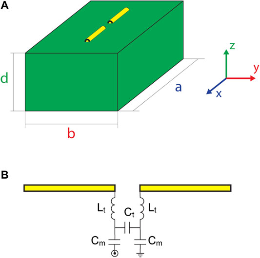
FIGURE 1. (A) The frame of reference used to calculate the cutoff frequency and to determine the type of the dielectric mode that propagates across dielectric blocks. The following transformation from this system to the system of coordinates in MRI environment would have to be made: x = z, y = x, z = y). (B) Matching network diagram.
Each dielectric mode was described by three subscripts: m, n, and l. Additionally, one superscript (x, y, or z) was used to indicate the direction of propagation for a given quasi-transverse electric (TE) mode. The fraction δ means that the given index was equal to 0 (see [19]). The geometry of each rectangular block and each εr value was determined as follows: first, we found the dimensions of the smallest possible square geometry for which the
where c is the velocity of light; m, n, and l are the dielectric mode indices (
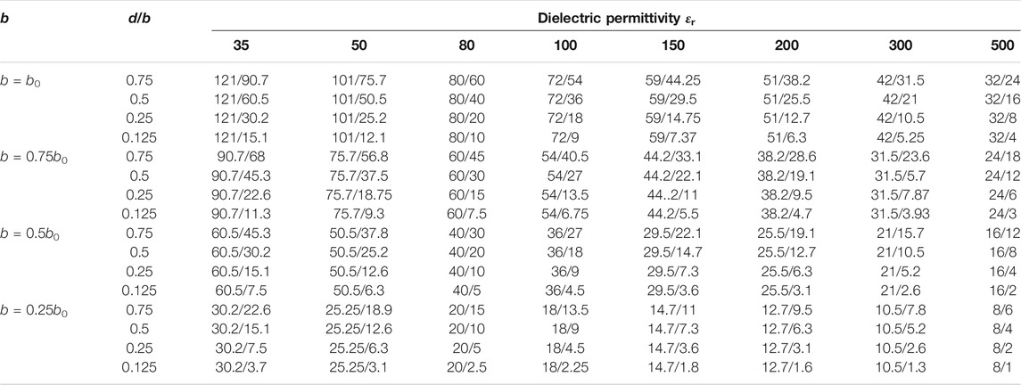
TABLE 1. The dimensions of rectangular blocks (in millimeters) used in simulations from Figure 2. The dimension a (a0) was constant for each εr value: 35 (242 mm), 50 (202 mm), 80 (160 mm), 100 (144 mm), 150 (118 mm), 200 (102 mm), 300 (84 mm), and 500 (64 mm). Four variations of b (b0, 0.75, 0.5b0, and 0.25b0) and for each b four d/b (0.75, 0.5, 0.25, and 0.125) ratios were investigated.
The transmit field efficiency in the spherical phantom could not be compared between all the blocks from Table 1 in a fair manner because higher εr values resulted in smaller blocks and shorter dipole antennas. For this purpose, a constant block geometry (a = 160 mm, b = 60 mm, and d = 7.5 mm) and dipole antenna length (28 mm per arm) was defined for all analyzed εr values. The dimensions were chosen so that such a block could be used as one of the elements in a close-fitting 8-channel transmit/receive array for brain imaging [11].
The effect of an air gap on the transmit field distribution in a cuboid phantom was studied for one larger block (0.75b0, d/b = 0.75) for each εr value. The cuboid phantom was chosen for this purpose because it provided good coupling (flat surface) to the rectangular dielectric block; the transmit field distribution in the cuboid phantom was also benchmarked against the results obtained for the spherical phantom (rounded surface). Five different air gaps were studied: 1, 2, 3, 4, and 5 mm for all εr values. These simulations were extended by investigating the y-component of the magnetic field
Plane wave simulations were conducted for six different wave number and electric field vector configurations with the following parameters: number of mesh cells = 681,000, excitation signal = Gaussian, center frequency = 297.2 MHz, and bandwidth = 300 MHz, amplitude = 1 V. The dielectric block (160 mm × 70 mm × 52.5 mm) was defined as the wave source according to the approach provided by Sim4Life, which is based on total-field/scattered-field (TF/SF) formulation (also called the plane-wave injector). In this method, only a certain region of the calculation domain, the total field region (the dielectric block in our case), propagates the plane wave.
Two dielectrically shortened dipole antennas (εr = 80) were designed, built, and evaluated in MR experiments: 160 mm × 70 mm × 52.5 mm (0.75b0, d/b = 0.75) and 160 mm × 70 mm × 17.5 mm (0.75b0, d/b = 0.25). The prototypes were built of a PMMA shell (wall thickness = 3 mm). The geometries were chosen so that different dielectric modes can be excited within the blocks. The reason for using εr = 80 was that water has an εr value close to 80 at 297.2 MHz. Water is readily available and easily imaged by MRI [22]. To visualize the dielectric modes within the different block geometries, deionized water was used, and the dipole antenna was tuned to 297.2 MHz and matched to 50 Ω.
MR experiments were conducted with a 7.0-T 68-cm bore scanner (Magnetom, Siemens Healthineers, Erlangen, Germany). A shielded cable trap, consisting of a capacitor soldered to the shield of the coaxial cable, was connected to each element and used in every experiment. MRI experiments were performed in one male subject (age = 29 years, BMI = 28.5 kg/m2), who had signed written consent approved by the local ethics committee, in three different regions of interest: head, calf, and wrist. It was not feasible to conduct additional experiments for other anatomical structures because the scanner used is dedicated to the human head. The goal was to investigate how different dielectric modes could propagate across various anatomical structures (with different loading geometries), given our prior knowledge on the differences between cuboid and spherical phantoms [16]. To visualize the magnetic field distribution within both blocks, standard gradient echo (GRE) imaging was used with the following parameters: repetition time (TR) = 8.6 ms, echo time (TE) = 4.0 ms, field of view (FOV) = 250 × 250 mm2, slice thickness = 7.0 mm, number of averages = 2, FA = 15°, and reference transmit voltage = 5 V. For in vivo experiments, deionized water, which produced a very-high-intensity signal, compromising the in vivo image quality, was replaced by heavy water (D2O, Sigma Aldrich, Germany), and a 2-mm acrylonitrile butadiene styrene board was placed between the block and the subject. In vivo images were acquired by 3D-GRE imaging with the following parameters: TR/TE = 6.5/2.82 ms, FOV = 256 × 240 mm2, slice thickness = 1.0 mm, number of averages = 1, FA = 4°, and reference transmit voltage = 100 V. The acquisition parameters of the RF pulse sequence were used to scan each body part.
To determine the effect of block geometry and dielectric permittivity on the transmit field distribution and efficiency within the spherical phantom, electromagnetic field simulations were performed (Figure 2). The transmit field distribution within the spherical phantom for d = 0.125b was the most consistent regardless of the combination of b/b0 and εr. Moreover, d = 0.125b (for b = 0.5b0 and b = 0.75b0) resulted in the highest transmit field efficiency in the center of the phantom for all εr values. The most apparent change in the transmit field distribution (two-side lobes and almost no transmit field along the z-axis) and decrease in the transmit field efficiency was observed for d = 0.75b (b = b0, b = 0.75b0, and b = 0.5b0) for all εr values (Figure 2). For d = 0.75b (b = 0.25b0), that effect was still present, but for the higher-εr blocks (εr ≥ 200). A similar change in the transmit field pattern as for d = 0.75b was also observed for thinner blocks with d = 0.5b. This was especially prominent for higher εr (εr ≥ 150). Local SAR10g values for each block are summarized in Table 2. Higher d/b ratios yielded lower SAR10g values for narrower blocks (b = 0.25b0 and b = 0.5b0), excluding d/b = 0.75, for the highest-εr values (εr ≥ 200). For wider blocks (b = 0.75b0 and b = b0), SAR10g was the highest for the thickest blocks (d/b = 0.75) excluding the lowest-εr values, 35 and 50 (the latter only for d/b = 0.5).
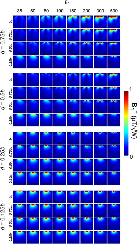
FIGURE 2. Transmit field distribution in the spherical phantom for various geometries (Table 1) of dipole-fed rectangular dielectric resonator antennas and dielectric permittivity εr (35, 50, 80, 100, 150, 200, 300, and 500). The distance between the bottom of the block and the phantom was 5 mm. Each column depicts different εr values. The figure was divided into four groups (starting from the top): d/b = 0.75, 0.5, 0.25, and 0.125. Each group consists of four rows: b = b0, 0.75b0, 0.5b0, and 0.25b0. Substantial differences in the transmit field pattern and efficiency can be observed between different geometries for a given εr, as well as for the same a/b/d ratio, but different εr values.
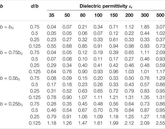
TABLE 2. Maximum local SAR10g values in W/kg provided for the simulations from Figure 2. The exact dimensions of the blocks can be found in Table 1. In general, for lower b values (0.5b0 and 0.25b0), the thicker blocks yielded lower was the SAR10g than their thinner counterparts. This trend changed for d/b = 0.75 for higher-εr blocks (300 and 500). For b = b0, SAR10g values for higher-εr blocks (200, 300, and 500) were found to be significantly higher for d/b = 0.75 than for d/b = 0.125.
To determine which εr provided the highest transmit field and SAR in the center of the spherical phantom, electromagnetic field simulations were performed using a constant block geometry and dipole antenna length (Figure 3). The electric field distribution was found to depend on εr of the block (Figure 3), and it was significantly different for higher-εr blocks (εr ≥ 200). The highest transmit field efficiency in the center of the phantom was obtained with εr = 300 (0.21 μT/√W) and εr = 200 (0.197 μT/√W), but at the cost of reduced SAR efficiency (0.103 μT/√W/kg and 0.126 μT/√W/kg). The highest SAR efficiency in the center was obtained with lower εr values: 0.149 μT/√W/kg for εr = 80, and 0.148 μT/√W/kg for εr = 50. The transmit efficiency (center of the phantom) with εr = 300 was higher by 33%, and the SAR efficiency was lower by 31% than with εr = 80. The transmit efficiency (center of the phantom) with εr = 200 was higher by 29%, and the SAR efficiency was lower by 15.5% than with εr = 80.
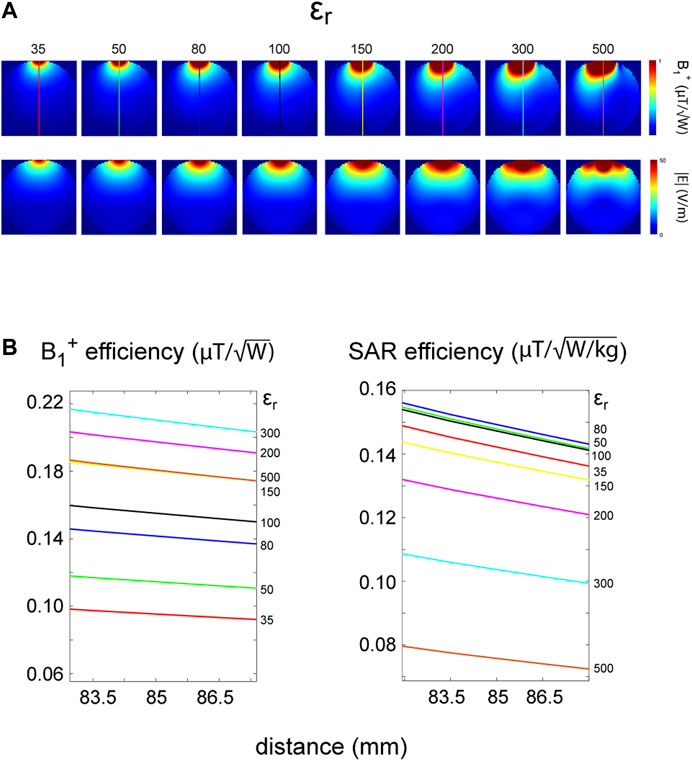
FIGURE 3. (A) Transmit field and electric field distribution within the spherical phantom for the constant block geometry (160 mm × 60 mm × 7.5 mm) and dipole antenna length as a function of dielectric permittivity εr (35, 50, 80, 100, 150, 200, 300, and 500). The air gap was 5 mm. (B) Transmit and SAR efficiency as functions of distance. The plots were zoomed in (85 mm on the x-axis corresponds to the center of the phantom) to better distinguish the differences between the blocks. The highest transmit field efficiency in the center of the phantom was obtained for εr = 300 (0.210 μT/√W) and εr = 200 (0.197 μT/√W) but at the cost of a reduced SAR efficiency (0.103 and 0.126 μT/√W/kg). The highest SAR efficiency in the center was obtained for lower εr values: 0.149 μT/√W/kg for εr = 80 and 0.148 μT/√W/kg for εr = 50. Note that in higher-εr blocks (300, 500), a higher-order mode
To investigate how physical separation between the dielectric block and the cuboid phantom can influence the transmit field pattern and efficiency, an air gap (1–5 mm) between the block and the phantom was assumed for one block geometry (b = 0.75b0, d = 0.75b) for all εr (Figure 4). The larger block was chosen because it produced a highly inefficient transmit field in the spherical phantom (Figure 2, second row). It was found for lower εr values (35 and 50) that, despite the air gap, the transmit field pattern was very similar to the one obtained with a direct contact between the block and the cuboid phantom, albeit with slightly lower efficiency. For higher εr values (εr ≥ 80), a significant difference in the transmit field pattern and efficiency could be observed. For εr = 80, the effect was present with a 3-mm air gap, while for higher εr values (εr ≥ 200), a 1-mm air gap was already sufficient, and the observed effect was much more prominent.
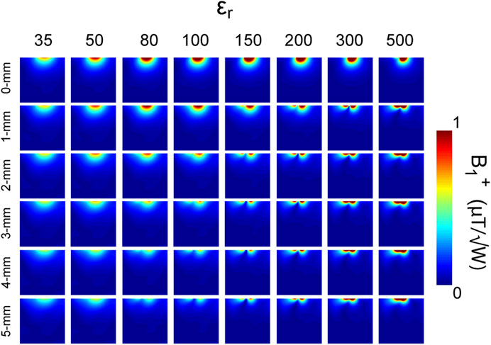
FIGURE 4. Transmit field distribution in the cuboid phantom as a function of dielectric permittivity of the block and the block/phantom physical separation. The geometry of one of the larger blocks was chosen (b = 0.75b0, d/b = 0.75—Table 1). The effect of five different sizes of an air gap (1, 2, 3, 4, and 5 mm) was investigated for all εr values (35, 50, 80, 100, 150, 200, 300, and 500). No significant change was noted in the transmit field pattern for lower εr values (35, 50) when the antenna was moved 5 mm away from the phantom. The transmit field changed significantly for higher εr values. The higher the εr value of the block, the lower the “threshold” size of the air gap, for which the transmit field pattern changed along with a decreased efficiency.
The impact of block/phantom physical separation and phantom geometry was further investigated by simulating the y-component of the magnetic field (Hy). Increasing the distance between the phantom and the block by 20 mm for the two lower-εr (35, 50) blocks resulted in Hy being mostly contained within the blocks (Figure 5A). For higher εr (200), the effect was already prominent with a 0.5-mm air gap, showing that the distance between the block and the phantom for the given εr value significantly influenced the transmit field distribution. The results were compared to those obtained previously for the spherical phantom (5-mm air gap; Figure 5B): Hy was mostly contained within the low-εr blocks (εr = 35 and 50) for the spherical phantom, while for the cuboid phantom, Hy propagated toward the phantom despite the 5-mm air gap.
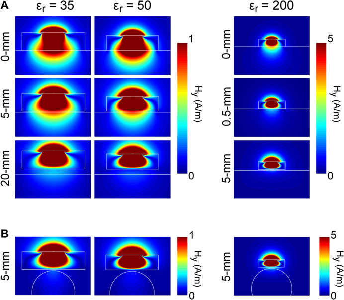
FIGURE 5. (A) The distribution of the y-component (in x–z plane) of the magnetic field (Hy) as a function of dielectric permittivity, phantom geometry, and block/phantom physical separation. White lines depict the boundaries of the blocks and the phantoms. For the direct contact case (cuboid phantom) as well as for smaller air gap (5-mm), Hy for lower-εr blocks (35, 50) coupled well to the phantom enabling the propagation of H-field in the z-direction. For the cuboid phantom (20-mm air gap) and lower-εr blocks, Hy was mostly confined within the blocks, especially for εr = 50. In the case of εr = 200, a similar effect was observed even with a 0.5-mm air gap. (B)Hy distribution in the cuboid phantom (5-mm air gap) was benchmarked against Hy distribution in the spherical phantom (5-mm air gap). The results showed that Hy distribution within the block (and therefore the transmit field efficiency) was significantly dependent on the loading geometry.
To investigate the transmit field distribution within different rectangular block geometries, PMMA boxes were filled with deionized water and imaged by gradient-recalled echo at low-flip angles. Based on the analysis of the simulated transmit field patterns and MR experiments (Figure 6), we interpreted the mode excited in the larger block (d = 0.75b) as
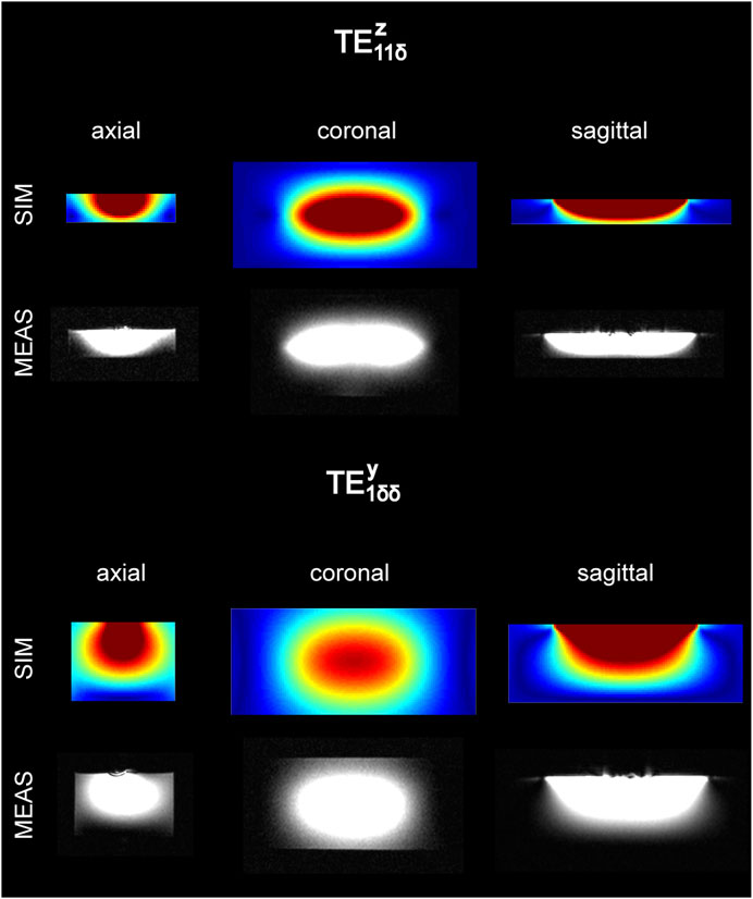
FIGURE 6. Visualization of dielectric modes: the comparison between the electromagnetic field simulations and magnetic resonance measurements for two elements: thinner one (d = 0.25b) and thicker one (d = 0.75b). The polymethylmethacrylate boxes were filled with deionized water, and their volumes were matched to the dimensions of the dielectric blocks described in the Methods section. Low-flip-angle gradient echo imaging was used. The simulations are in an excellent agreement with the measurements and show significantly different magnetic field distribution between the blocks. The mode that propagates within the thinner block was interpreted as
To understand the impact on an MRI experiment of the different dielectric modes that can be excited by a dielectrically shortened dipole antenna, in vivo studies were performed with one male subject. Two block geometries were investigated: d = 0.25b, d = 0.75b. In vivo images of the head, calf, and wrist were obtained (Figure 7). The thinner block provided highly superior image quality for all tissues compared to its thicker counterpart, which yielded very noisy images (very low to no SNR) for the brain, calf, and wrist. However, qualitative differences were apparent among the images obtained using the larger block, and the best image quality was obtained with the wrist, which provided a flatter surface. Significantly, lower image quality was noted for the calf while the lowest was for the head, the body part with the highest level of curvature in this study.
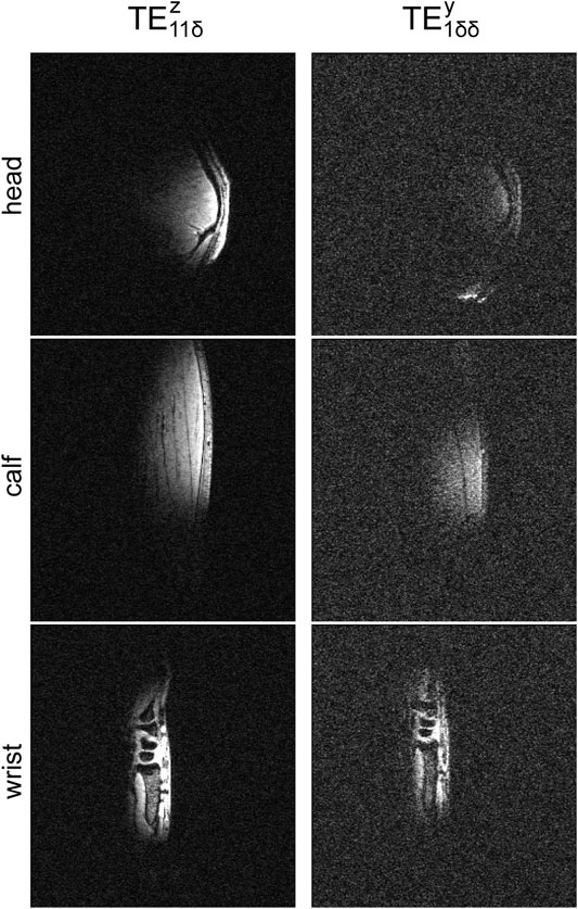
FIGURE 7. In vivo MRI experiments in one human male subject using two blocks: thinner (d/b = 0.25) and thicker one (d/b = 0.75). Three different regions of interest (head, calf, and wrist) were investigated. The quality of all the images was significantly compromised for the larger block (very noisy). The images obtained using the smaller block were superior, and all the tissues can be clearly delineated. Even though the quality of images (larger block) was very low, it can be observed that the quality of the image of the wrist (low level of curvature and almost flat surface) was the highest. The worst quality was noticed for the image of the head (high level of curvature). These results can be benchmarked against the ones obtained for the cuboid (wrist, Figure 5) and the spherical phantom (head, Figure 5). The images have the same absolute intensity.
To determine whether the larger block (160 mm × 70 mm × 52.5 mm) could still be used as an efficient RF antenna, plane-wave simulations for six different orientations of the magnetic field vector
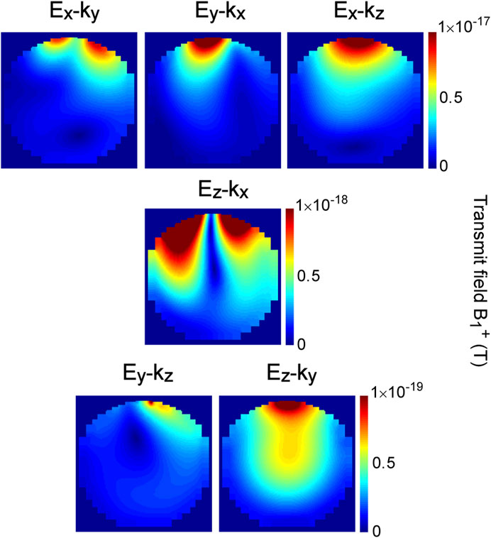
FIGURE 8. Plane-wave simulations: the transmit field distribution in the spherical phantom (5-mm air gap) for one dielectrically shortened dipole antenna (εr = 80, 160 mm × 70 mm × 52.5 mm). Six different transmit field patterns arise from six different orientations of the
This study demonstrates for the first time why certain dipole-fed rectangular dielectric resonator antennas for MRI at 7 T can preserve (and others do not) the transmit field distribution and efficiency when the dielectric block and the sample are physically separated. We showed that different types of quasi-transverse electric modes, which were induced in the analyzed block geometries by dipole antennas, played the most critical role in this context:
By using the term “quasi-
Dipole-fed rectangular dielectric resonator antennas, in which the
The propagation of quasi-transverse dielectric modes depends mainly on the ratio of the block dimensions (Figure 1): a, b, and d (if the feeding type did not change; Figure 2) and on the feeding type (if the dimensions were constant; Figure 8). Our results show that when d was sufficiently smaller than b, a quasi-
We found that a relatively small d/b ratio (d = 0.5b and d = 0.75b; for εr = 500 even when d = 0.25b) results in an inefficient transmit field in the spherical phantom (Figure 2): high-εr blocks (εr ≥ 200) can produce an inefficient transmit field for much smaller d/b ratios than low-εr blocks (35, 50). This indicates that
Note, however, that decreasing d can result in needing larger inductors to tune the antenna, which has an impact on the transmit field efficiency. Thinner blocks are also expected to yield higher SAR values than their thicker counterparts, excluding the wider blocks with b = b0 and b = 0.75b0, especially for higher εr values (εr ≥ 200). Therefore, certain tradeoffs would have to be considered and accepted depending on the application. If the block dimension d is properly chosen for a given a and b, the latter two play the key role in overall antenna performance. With d = 0.125b, the most efficient transmit field was observed with b = 0.5b0 and b = 0.75b0 (for d = 0.125b) for all εr values. The transmit field efficiency for b = 0.5b0 was slightly higher (∼2.5%) than b = 0.75b0. However, on average, 20% higher inductance was needed to tune the antennas with b = 0.5b0. Losses associated with higher inductance were not included in the simulations, and they are expected to affect the transmit field efficiency. Moreover, the SAR efficiency for b = 0.5b0 was ∼7.2% lower than that for b = 0.75b0. Interestingly, according to Eq. 1, the cutoff frequency for the
Transmit field patterns for d = 0.75b (Figure 2) should not be confused with the pattern that would be expected for a standalone loop coil at 297.2 MHz. A transmit field pattern similar to the one for the loop coil can be obtained by replacing the dipole-with a loop-type excitation (see Ey-kx excitation from Figure 8). Note that for the ratio d = 0.75b, the
The above considerations provide additional evidence why dielectric modes are critical in dielectrically shortened dipole antennas, given the fact that the particular b/b0 and d/b ratio increments used in our study were chosen in an arbitrary fashion. Our data also suggest that the propagation of dielectric modes can become a limiting factor in miniaturization of rectangular dielectric blocks in UHF-MRI. We observed that a more efficient transmit field for dielectrically shortened dipole antennas can be achieved when, for a given geometry and εr, the cutoff frequency for the
The effect of the dielectric permittivity of the block on the transmit field performance was analyzed by keeping the distance between the block and the spherical phantom constant (5 mm) along with the geometry of the block (a/b/d ratio) and dipole antenna (wire) length (Figure 3). The geometry was chosen such that it could be used as a building block of an 8-channel array [11]. Our data showed that as expected for higher εr values, the electromagnetic field is more concentrated near the block [23]. This led to higher transmit efficiency in the periphery for higher-εr blocks (especially for εr = 300 and 500, in which the
The electromagnetic field simulations also showed that the larger rectangular dielectric block, which was coupled to the
The analysis of the transmit field produced within the cuboid phantom by bigger blocks (b = 0.75b0, d = 0.75b) with εr values ranging from 35 to 500 showed that the distance between the block and the phantom for a given εr is critical for the transmit field pattern and efficiency (Figure 4). For each εr value, five different air gaps (1–5 mm) were investigated, and, despite the air gap, the transmit field pattern for lower εr values (35 and 50) was very similar to the one obtained with a direct contact between the block and the phantom, albeit with a slightly lower efficiency. For higher εr values (εr ≥ 80), we observed a significant difference in the transmit field pattern and efficiency dependent on the air gap size. For εr = 80, an altered transmit field pattern along with a decreased efficiency was present with a 3-mm air gap, while for higher εr values (εr ≥ 200) a 1-mm air gap was already sufficient, and the observed effect was much more prominent. This can be explained by the different εr values of the block. The higher the εr value, the higher the concentration of the electromagnetic field within the block and therefore the lower the coupling to the phantom (Hy remains well confined within the block).
Additional simulations demonstrated that a change in the transmit field pattern and efficiency (with Hy mostly confined within the block) can be still observed with lower εr values but requires larger air gaps (Figure 5). In general, the lower the εr value, the greater the “threshold” air gap size required to have Hy confined within the block and not significantly present in the phantom. In the case of higher εr values (200), the effect was even observed for smaller air gap (0.5 mm). The latter highlights the importance of this study because the “perfect direct contact” condition seems to be difficult to achieve in practice because even such tiny air gaps can influence antenna performance. Note that even with a direct contact for εr = 500, a slight change in the transmit field pattern can be already observed (Figure 4). The results obtained with the cuboid phantom (5-mm air gap) were compared to the data obtained with the spherical phantom (Figure 5). All the blocks included in the comparison supported the
As spherical and rectangular phantom geometries can be considered ideal experimental conditions that may not mimic the practical situation, we performed preliminary in vivo experiments involving one male subject, focusing on three different organs: the head, calf, and wrist (Figure 7). All the investigated anatomical structures had different levels of curvature: human head (high), calf (medium), and wrist (low, almost flat). Dielectric blocks with d = 0.25b and 0.75b were used. All the images obtained when using the thicker block were substantially inferior to the ones when using the thinner block. We observed subtle differences between the images obtained using the thicker block: the image of the wrist had the highest quality, while the image of the head was very noisy, with almost no anatomical details visible, and the calf image quality was intermediate. In vivo data can be compared with our simulations using spherical and cuboid phantoms; the wrist was similar to the flat surface of the cuboid phantom, and the head was obviously more rounded like the spherical phantom. Note that the thicker block used in the in vivo experiments was very close to the optimal design described by Ipek et al. [14], yet its performance was very low. To summarize, when anatomical structures can be considered flat with respect to the bottom surface of the rectangular block, such as the wrist, they can couple better to the antenna’s
An arbitrarily chosen conductivity σ (constant for each block) can be considered one of the study’s limitations because σ is expected to increase with εr of the block. Therefore, the authors recommend to interpret with caution the results concerning transmit efficiency. This, however, is not expected to significantly influence the data obtained in the context of different dielectric modes and transmit field patterns which were affected by them. Also, we would like to point out that expected σ increase with εr should have a rather limited impact on future developments, given the fact that there are available technologies which enable manufacturing ceramic blocks with a very high εr value (range of thousands) along with a very low σ value of 0.001 S/m (roughly 60 times lower than the one used in this study).
In the context of our study, previous work can be divided into two groups: (a) reports in which different, mainly loop-coupled, dielectric structures were used with a clear motivation to induce desired dielectric modes [23–26, 28] and (b) reports in which dielectric structures were used solely for the purpose of shortening dipole antennas [6, 11, 13, 15, 29, 30]. In the case of (a), different types of dielectric modes were investigated, while in the case of (b), even if dielectric modes and their impact on antenna performance were considered by the authors, it was not mentioned in any of those reports. Based on our results, we believe that (a) and (b) should not be considered separately, and this is particularly apparent when the cutoff frequency for a given block geometry and εr is below the NMR frequency. In this study, we showed that dielectric modes play a key role in the antenna’s overall performance when the block is separated from the sample. Therefore, by treating such an element as a dipole-fed dielectric resonator antenna rather than dielectrically shortened dipole antenna, we highlight the impact of dielectric modes on overall performance of a dipole antenna. This aspect could be further investigated by looking into transmit field patterns produced by combinations of different dipole antenna geometries with different dielectric structures. We have already conducted a study [16], in which we investigated the elements developed by Winter et al. [11], Sanchez-Heredia et al. [13], and a scaled-version of Raaijmakers et al. [6], and we found that exactly the same types of modes demonstrated in this work were excited.
We conclude that the approach presented in this study can offer guidance and new insights into the design of rectangular dielectric resonator antennas for MRI at 7 T, given the growing number of such antenna designs for UHF-MRI [29–31]. These findings should also be relevant for geometries other than the rectangular ones and for higher Larmor frequencies than the one investigated in this study.
The original contributions presented in the study are included in the article/Supplementary Material, and further inquiries can be directed to the corresponding author.
The studies involving human participants were reviewed and approved by the Swiss cantonal ethics committee. The patients/participants provided their written informed consent to participate in this study. Written informed consent was obtained from the individual(s) for the publication of any potentially identifiable images or data included in this article.
DW designed the study, performed all of the numerical simulations, designed and built the prototypes used in in vivo experiments, analyzed and interpreted the data, prepared the figures, and wrote the manuscript. RG analyzed and interpreted the data and revised the manuscript.
The authors declare that the research was conducted in the absence of any commercial or financial relationships that could be construed as a potential conflict of interest.
The authors wish to thank Hikari Yoshihara (EPFL) for proofreading the manuscript, Lijing Xin (CIBM and EPFL) for helping with in vivo experiments, and Andre Kuehne (MRI.TOOLS, Berlin, Germany) for a helpful discussion. They acknowledge access to the facilities and expertise of the CIBM Center for Biomedical Imaging, a Swiss research center of excellence founded and supported by Lausanne University Hospital (CHUV), University of Lausanne (UNIL), Ecole polytechnique fédérale de Lausanne (EPFL), University of Geneva (UNIGE), and Geneva University Hospitals (HUG).
1. Ladd ME, Bachert P, Meyerspeer M, Moser E, Nagel AM, Norris DG, et al. Pros and Cons of Ultra-high-field MRI/MRS for Human Application. Prog Nucl Magn Reson Spectrosc (2018) 109:1–50. doi:10.1016/j.pnmrs.2018.06.001
2. Roemer PB, Edelstein WA, Hayes CE, Souza SP, Mueller OM. The NMR Phased Array. Magn Reson Med (1990) 16:192–225. doi:10.1002/mrm.1910160203
3. Sodickson DK, Manning WJ. Simultaneous Acquisition of Spatial Harmonics (SMASH): Fast Imaging with Radiofrequency Coil Arrays. Magn Reson Med (1997) 38:591–603. doi:10.1002/mrm.1910380414
4. Pruessmann KP, Weiger M, Scheidegger MB, Boesiger P. SENSE: Sensitivity Encoding for Fast MRI. Magn Reson Med (1999) 42:952–62. doi:10.1002/(sici)1522-2594(199911)42:5<952:aid-mrm16>3.0.co;2-s
5. Griswold MA, Jakob PM, Heidemann RM, Nittka M, Jellus V, Wang J, et al. Generalized Autocalibrating Partially Parallel Acquisitions (GRAPPA). Magn Reson Med (2002) 47:1202–10. doi:10.1002/mrm.10171
6. Raaijmakers AJE, Ipek O, Klomp DWJ, Possanzini C, Harvey PR, Lagendijk JJW, et al. Design of a Radiative Surface Coil Array Element at 7 T: the Single-Side Adapted Dipole Antenna. Magn Reson Med (2011) 66:1488–97. doi:10.1002/mrm.22886
7. Raaijmakers AJE, Italiaander M, Voogt IJ, Luijten PR, Hoogduin JM, Klomp DWJ, et al. The Fractionated Dipole Antenna: A New Antenna for Body Imaging at 7 T Esla. Magn Reson Med (2016) 75:1366–74. doi:10.1002/mrm.25596
8. Ertürk MA, Raaijmakers AJE, Adriany G, Uğurbil K, Metzger GJ. A 16‐channel Combined Loop‐dipole Transceiver Array for 7 T Esla Body MRI. Magn Reson Med (2017) 77:884–94. doi:10.1002/mrm.26153
9. Clément J, Gruetter R, Ipek Ö. A Combined 32‐channel Receive‐loops/8‐channel Transmit‐dipoles Coil Array for Whole‐brain MR Imaging at 7T. Magn Reson Med (2019) 82:1229–41. doi:10.1002/mrm.27808
10. Lattanzi R, Wiggins GC, Zhang B, Duan Q, Brown R, Sodickson DK. Approaching Ultimate Intrinsic Signal-To-Noise Ratio with Loop and Dipole Antennas. Magn Reson Med (2018) 79:1789–803. doi:10.1002/mrm.26803
11. Winter L, Özerdem C, Hoffmann W, Santoro D, Müller A, Waiczies H, et al. Design and Evaluation of a Hybrid Radiofrequency Applicator for Magnetic Resonance Imaging and RF Induced Hyperthermia: Electromagnetic Field Simulations up to 14.0 Tesla and Proof-Of-Concept at 7.0 Tesla. PLoS One (2013) 8:e61661. doi:10.1371/journal.pone.0061661
12. Oezerdem C, Winter L, Graessl A, Paul K, Els A, Weinberger O, et al. 16-channel bow Tie Antenna Transceiver Array for Cardiac MR at 7.0 Tesla. Magn Reson Med (2016) 75:2553–65. doi:10.1002/mrm.25840
13. Sanchez-Heredia JD, Avendal J, Bibic A, Lau BK. Radiative MRI Coil Design Using Parasitic Scatterers: MRI Yagi. IEEE Trans Antennas Propagat (2018) 66:1570–5. doi:10.1109/TAP.2018.2794400
14. Ipek O, Raaijmakers A, Lagendijk J, Luijten P, van den Berg C, Optimization of the Radiative Antenna for 7-T Magnetic Resonance Body Imaging, Concepts Magn Reson (2013) 43B. p. 1–10. doi:10.1002/cmr.b.21224
15. Eigentler TW, Winter L, Han H, Oberacker E, Kuehne A, Waiczies H, et al. Wideband Self‐Grounded Bow‐Tie Antenna for Thermal MR. NMR Biomed (2020) 33:33. doi:10.1002/nbm.4274
16. Wenz D, Gruetter R. Dielectrically-Shortened Dipole Antennas for MRI at 7.0 T: Thick or Thin? Proc Intl Soc Mag Reson Med (2020) 28:4087.
17. Mongia RK, Bhartia P. Dielectric Resonator Antennas-A Review and General Design Relations for Resonant Frequency and Bandwidth. Int J Microw Mill-Wave Comput-Aided Eng (1994) 4:230–47. doi:10.1002/mmce.4570040304
18. Keyrouz S, Caratelli D. Dielectric Resonator Antennas: Basic Concepts, Design Guidelines, and Recent Developments at Millimeter-Wave Frequencies. Int J Antennas Propagation (2016) 2016:1–20. doi:10.1155/2016/6075680
20. Pan YM, Leung KW, Lu K. Study of Resonant Modes in Rectangular Dielectric Resonator Antenna Based on Radar Cross Section. IEEE Trans Antennas Propagat (2019) 67:4200–5. doi:10.1109/TAP.2019.2911198
21. Wen H, Jaffer FA, Denison TJ, Duewell S, Chesnick AS, Balaban RS. The Evaluation of Dielectric Resonators Containing H2O or D2O as RF Coils for High-Field MR Imaging and Spectroscopy. J Magn Reson Ser B (1996) 110:117–23. doi:10.1006/jmrb.1996.0019
22. Webb AG. Visualization and Characterization of Pure and Coupled Modes in Water-Based Dielectric Resonators on a Human 7T Scanner. J Magn Reson (2012) 216:107–13. doi:10.1016/j.jmr.2012.01.013
23. O’Reilly TPA, Ruytenberg T, Webb AG. Modular Transmit/receive Arrays Using Very-High Permittivity Dielectric Resonator Antennas: Very-High Permittivity DRA Arrays. Magn Reson Med (2018) 79:1781–8. doi:10.1002/mrm.26784
24. Aussenhofer SA, Webb AG. Design and Evaluation of a Detunable Water-Based Quadrature HEM11 Mode Dielectric Resonator as a New Type of Volume Coil for High Field MRI. Magn Reson Med (2012) 68:1325–31. doi:10.1002/mrm.24451
25. Aussenhofer SA, Webb AG. An Eight-Channel Transmit/receive Array of TE01 Mode High Permittivity Ceramic Resonators for Human Imaging at 7T. J Magn Reson (2014) 243:122–9. doi:10.1016/j.jmr.2014.04.001
26. Ruytenberg T, Webb AG. Design of a Dielectric Resonator Receive Array at 7 Tesla Using Detunable Ceramic Resonators. J Magn Reson (2017) 284:94–8. doi:10.1016/j.jmr.2017.09.015
27. Ruytenberg T, O'Reilly TP, Webb AG. Design and Characterization of Receive-Only Surface Coil Arrays at 3T with Integrated Solid High Permittivity Materials. J Magn Reson (2020) 311:106681. doi:10.1016/j.jmr.2019.106681
28. Moussu MAC, Glybovski SB, Abdeddaim R, Craeye C, Enoch S, Tihon D, et al. Imaging of Two Samples with a Single Transmit/receive Channel Using Coupled Ceramic Resonators for MR Microscopy at 17.2 T. NMR Biomed (2020) 33:e4397. doi:10.1002/nbm.4397
29. Oberacker E, Kuehne A, Oezerdem C, Nadobny J, Weihrauch M, Beck M, et al. Radiofrequency Applicator Concepts for thermal Magnetic Resonance of Brain Tumors at 297 MHz (7.0 Tesla). Int J Hyperthermia (2020) 37:549–63. doi:10.1080/02656736.2020.1761462
30. Woo MK, DelaBarre L, Lagore R, Jungst S, Yang Q, Zhang B, et al. Improved B1+ Efficiency of a Dipole Antenna Equipped with High Dielectric Constant (HDC) Materials at 10.5T. Proc Intl Soc Mag Reson Med (2019) 27:1498.
Keywords: dielectric resonator antenna, dipole antenna, dielectric mode, radio frequency coil, ultrahigh field magnetic resonance imaging, 7 Tesla
Citation: Wenz D and Gruetter R (2021) Dipole-Fed Rectangular Dielectric Resonator Antennas for Magnetic Resonance Imaging at 7 T: The Impact of Quasi-Transverse Electric Modes on Transmit Field Distribution. Front. Phys. 9:675509. doi: 10.3389/fphy.2021.675509
Received: 03 March 2021; Accepted: 10 May 2021;
Published: 15 June 2021.
Edited by:
Elmar Laistler, Medical University of Vienna, AustriaReviewed by:
Andrew Webb, Leiden University, NetherlandsCopyright © 2021 Wenz and Gruetter. This is an open-access article distributed under the terms of the Creative Commons Attribution License (CC BY). The use, distribution or reproduction in other forums is permitted, provided the original author(s) and the copyright owner(s) are credited and that the original publication in this journal is cited, in accordance with accepted academic practice. No use, distribution or reproduction is permitted which does not comply with these terms.
*Correspondence: Daniel Wenz, ZGFuaWVsLndlbnpAZXBmbC5jaA==
Disclaimer: All claims expressed in this article are solely those of the authors and do not necessarily represent those of their affiliated organizations, or those of the publisher, the editors and the reviewers. Any product that may be evaluated in this article or claim that may be made by its manufacturer is not guaranteed or endorsed by the publisher.
Research integrity at Frontiers

Learn more about the work of our research integrity team to safeguard the quality of each article we publish.