
94% of researchers rate our articles as excellent or good
Learn more about the work of our research integrity team to safeguard the quality of each article we publish.
Find out more
ORIGINAL RESEARCH article
Front. Phys. , 24 May 2021
Sec. Optics and Photonics
Volume 9 - 2021 | https://doi.org/10.3389/fphy.2021.664864
This article is part of the Research Topic Terahertz Sensing and Diagnosis View all 7 articles
A broad range of terahertz (THz) metamaterials have been developed for refractive index sensing. However, most of these metamaterials barely make sufficient use of the excited electric field which is crucial to achieve high sensitivity. Here, we proposed a metamaterial sensor possessing electromagnetically induced transparency (EIT) resonance that is formed by the interference of dipole and quadrupole resonance. In particular, the strengthening of light-matter interaction is realized through substrate etching, leading to a remarkable improvement in sensitivity. Hence, three kinds of etching mode were presented to maximize the utilization of the electric field, and the corresponding highest sensitivity is enhanced by up to ~2.2-fold, from 0.260 to 0.826 THz/RIU. The proposed idea to etch substrate with a strong light-matter interaction can be extended to other metamaterial sensors and possesses potential applications in integrating metamaterial and microfluid for biosensing.
In recent years, the trends of metamaterial research have progressed toward the realization of particular functions by constructing customized metasurfaces to control its optical properties [1–5], thereby creating extraordinary opportunities in the field of various functional devices like modulators, absorbers, and sensors [6–9]. Recently, researchers have shown an increased interest in the electromagnetically induced transparency (EIT) phenomenon in metamaterials, which is actually a quantum interference effect that forms a narrow transparent window within a broad absorption spectral region in multiple-level atomic systems [10–15]. Due to the strong interference of two resonant modes, EIT resonance only depends on the non-radiation damping, which makes it sensitive to the changes in the surrounding dielectric environment extremely [16]. What is more, by controlling the coupling between two resonant modes, highly desirable EIT resonance can be obtained with high quality (Q) factor, which is capable of detecting weak shifts in the resonance frequency [17]. Therefore, such excellent properties make EIT effective in metamaterials with great attraction for its potential in serving as a biochemical sensing platform [18].
Terahertz (THz) radiation has attracted much attention due to its unique qualities like non-destructive, non-contact, and unmarked [19–21]. More importantly, many molecules possess unique spectral absorption characteristics owing to their vibrational and rotational levels at THz frequencies, meaning THz metamaterials have shown great application prospects in biological and chemical sensing [18, 22–25]. In general, THz metamaterial sensors with high sensitivity should exhibit a concentrated effect of high-density electromagnetic fields that will drive molecules and THz radiation to have strong interactions. In recent years, various methods have been utilized to enhance the light–matter interaction between the THz wave and the analytes, such as optimized Q/Veff metasurface [26], metamaterial absorber integrated microfluidic [27], and HR-Si prism coupled with a tightly confined SSPPs mode [28]. The key question is how to place the analyte where the density of the electric field is the strongest [29]. In most cases, the design of metamaterials was of greater concern to excite different resonant modes [9, 22, 23, 30, 31]. However, the part of the electric field that permeates into the substrate has been wasted, which means that the light-matter interaction is limited, resulting in the sensing performance remaining hindered.
In this work, we proposed a novel scheme for the formation of EIT resonance at THz frequencies in planar metamaterial which is composed of a cut wire (CW) and a U-shaped split ring (U-SRR). In order to maximize the utilization of the excited electric field, we proposed three etching modes with different etching areas. A significant enhancement of the sensitivity is realized due to the fact that the electric field that permeates the substrate also interacts with the analyte after etching. The results show that when the entire substrate around the metamaterial is etched, the increase in sensitivity is at most about 2.2-fold. Furthermore, the relationship between etching volume and sensitivity is analyzed, the sensitivity stepwise increases as the etching area increases until reaching a maximum. The reported method of the strengthening of the light–matter interactions is largely suitable for various sensors with different resonances.
A schematic diagram of the metamaterial arrays containing the etched regions, along with the geometric of one unit cell is shown in Figure 1A. The unit cell is composed of a CW and a U-SRR, which is supported on the top of 50 μm-thick quartz substrate. The trench is etched at the electric field excitation, which is repeated for every CW/U-SRR element in the array. The etched shape adopts an L-shape with a length of m = 30 μm, a width of n = 30 μm and a height of t = 20 μm. The geometric parameters of one unit cell are as follows: length and width of the U-SRR are l = 60 μm and s = 64 μm, the CW has the same l and width of the line is w = 6 μm. The period of unit cell along x (Px) and y directions (Py) are 88 μm and 102 μm. The coupling distance between the CW and the U-SRR is set to g = 4 μm. The thickness of both of the resonators is tAl = 200 nm. A Drude model is adopted for the description of the optical properties of Al in the THz regime, which is defined as, , where the plasma frequency and the damping constant γ = 1.22 × 10¹⁴rad/s [32]. The complex reflective indexes of quartz is taken as ñ = 1.94 + 0.002i [33]. The electric field of the incident plane wave is polarized in the x direction. The simulated results are acquired using the commercial software Lumerical, three-dimensional finite difference time-domain (FDTD) solutions. Periodic boundary conditions are employed both in the x and y directions, and perfectly matched layers (PMLs) are adopted in the z direction along the propagation of the incident plane wave. Figures 1B–D shows the unit cell and the different etching modes, where the Figure 1B represents the L-shape trenches etching in the four corners, the Figure 1C shows the trench shape changes from L-shape to hollow square and the Figure 1D means the entire substrate around the metamaterial is etched.
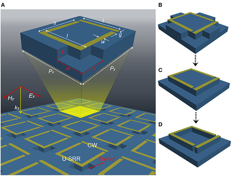
Figure 1. The THz metamaterial arrays with different etching modes. (A) The schematic diagram of the EIT metamaterial with an L-shape trench, the unit cell dimensions are depicted in the inset, where Px = 88 μm, Py = 102 μm, l = 60 μm, s = 64 μm, w = 6 μm, g = 4 μm, m = 30 μm, n = 30 μm and t = 20 μm. The unit cell with (B) the L-shape trenches etching in the four corners, (C) etching hollow square shape, and (D) entire substrate around the metamaterial is etched.
To reveal the generation mechanism of the EIT effect in the design metamaterial, we designed three sets of periodic structural unit cells, an individual CW and U-SRR, and a combination of both, respectively. Figure 2A shows the corresponding transmission spectra. The CW is strongly coupled with the incident plane wave and possesses a spectrally broad dipole resonance at 1.40 THz, as the red curve shows. However, the U-SRR exhibits a quadrupole resonance with a narrow bandwidth relatively at 1.50 THz due to the weak coupling with the incident plane wave, as the black curve shows. Q-factor is defined as the resonant frequency f 0 divided by the full width at half maximum: Q = f 0/FWHM, the dipole resonance exhibits a low Q-factor (Q = 6.8), acting as the bright mode, and the Q-factor of the quadrupole resonance is relatively high (Q = 17.1), acting as another bright mode. When both structures with large different Q-factors are arranged into the unit cell, a narrow transparency window with high spectral transmission emerges at 1.47 THz with a high Q-factor about 80.3.

Figure 2. The generation mechanism of the EIT effect. (A) The transmission spectra of the CW, the U-SRR and the EIT metamaterial. The electric field and surface charge density distributions of (B,E) 1.40 THz, (C,F) 1.50 THz, and (D,G) 1.47 THz of the EIT metamaterial.
We further elucidate the coupling between two bright modes through plotting the electric field and surface charge density distributions at three resonant frequencies. As shown in Figure 2B, the electric field mainly intensifies at two ends which is a typical dipole resonance at 1.40 THz, and correspondingly in Figure 2E, it can be clearly observed that the opposite charges are distributed symmetrically along the CW. While at 1.50 THz, a strong concentration of the electric field in four corners of the U-SRR in Figure 2C, and a large amount of the opposite charges which accumulate in both of the corners of the left side is opposite to that of the right side, making them appear as quadrupole resonance [34] in Figure 2F. Due to the resonance detuning, both resonators are excited simultaneously as shown in Figure 2D, while the induced currents of two resonators are out of phase by π which appears as a jump of the positive and negative charges of the CW in Figure 2G, the dipole and quadrupole resonance modes interfere strongly emerging the narrow EIT transparency window [35, 36].
To understand the effect of introducing trenches on the EIT resonance, we etched an L-shape trench in the upper left corner of the U-SRR. Figure 3A presents the transmission spectra of the EIT metamaterial with and without the trench, and the inset shows the position of the trench clearly. It is obvious that the resonant frequency increases from 1.47 to 1.55 THz as the trench is etched, and the Q-factor of the EIT resonance decreases from 80.3 to 39.6. Furthermore, only the right side of the EIT resonance is offset, while the left side is almost consistent.
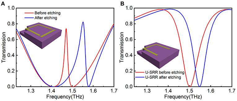
Figure 3. The transmission spectra of (A) the EIT metamaterial and (B) the U-SRR before and aftre etching an L-shape trench.
Since the trench is located in the U-SRR, the spectra of the individual U-SRR arrays with and without trench is shown in the Figure 3B. The resonant frequency presents a blueshift as well, and the Q-factor is almost in line, the slight increase is more due to the enhancement of the resonant frequency. The quadrupole resonance excited by the U-SRR can be interpreted as higher-order plasmon resonant mode [37]. Furthermore, this resonant mode can be described as approximately plasmon dipole resonance with the frequency [30], where d is the equivalent length of the structure and εeff is the effective dielectric constant of the surrounding medium. In general, εeff is dependent on the dielectric constant of the electric field being excited, as the frequency of the LC resonance relies strongly on the effective dielectric constant in the gap area [38]. Therefore, we can significantly reduce εeff through introducing trenches at the electric field excitation, further resulting in the increase of the resonant frequency which shows a blueshift. It has been proved that the EIT resonance is formed by the coupling of dipole and quadrupole resonance. When the trench is etched only at the upper left corner of the structure where the electric field of U-SRR is excited, the quadrupole resonance has a blueshift and leads to the increase of the EIT resonant frequency eventually.
In order to obtain the optimal etching depth, we plot yz and xz cross-sections (without introducing the L-shaped trench) of the electric field at different positions around the metamaterial structure in Figures 4C–H and the specific locations are shown in the electric field distribution diagram of EIT resonance in Figure 4A. The spacing of each cross-section is set to 2 μm for both yz and xz. It is clear that the electric field has a tremendous reinforcement near the structure and gradually weakens as it is farther away from the structure, and shows the same weakening as the depth increases. In addition, the same discovery is made for the xz cross-sections. To ensure the full use of the electric field based on the rationality of the design, we set the etched shape to be L-shaped and maximize the width of the L-shape. The length of the two sides of the L-shape is set to 30 μm to ensure as much overlap as possible between the analyte and the electric field. In order to avoid the problem of structural collapse during the process of adding analytes, the substrate etching is selected in the area where there is no structure. Figures 4I,J shows the electric field cross-sections at positions 1 and 4 after the introduction of L-shaped trench, due to the decrease in εeff of the L-shaped trench area after etching, the penetration of the electric field in the -z direction is strengthened. However, the enhancement of the electric field is still concentrated around the metal structure, and the intensity becomes extremely weak after trench depth (t) reaches 20 μm, although the depth of the penetration increases. The simulation results well confirmed the conclusion as the spectra with different trench depths (t) shown in Figure 4B. As the etching depth expands, the blue shift of the EIT peak continues to increase until it reaches a saturation value of about 20 μm.
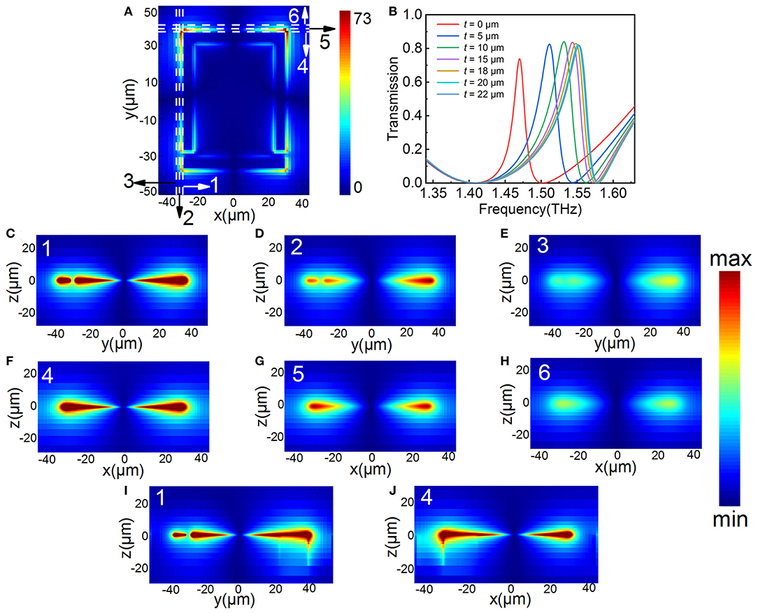
Figure 4. Electric field distribution at various cross-sections (without introducing the L-shaped trench) and the optimal etching depth. (A) The electric field distribution of EIT resonance and positions of different cross-sections from 1–6. (B) The transmission spectra of the EIT metamaterial with different t values. (C–E) The yz cross-sections of the positions 1–3. (F–H) The xz cross-sections of the positions 4–6. (I,J) The cross-sections of the positions 1 and 4 with the introduction of the L-shaped trench.
To give an insight into the influence of trench on the sensing sensitivity of the metamaterial, a 20 μm-thick analyte with a refractive index of n from 1 to 1.4 is covered in the surface of the metamaterial and the trench is filled with analyte as well. Figures 5A–C shows the transmission spectra of the EIT metamaterial with and without trench, Figure 5A stands for before etching, Figure 5B represents the introduction of an L-shape trench, and Figure 5C refers to etching trenches at all four corners of the structure, with each inset showing specific circumstances of etching. It is clear that the resonant frequency presents a redshift with the increase of n in each case. Whereas, while the value of the redshift is different compared with before etching, the redshift increases with the increase of the number of trenches introduced. To better compare the sensitivity of different cases, the variation frequency of EIT resonance versus refractive index of analyte is plotted in Figure 5D. The resonant frequencies are linearly distributed along the refractive index for all three cases. The straight lines are linear fits given by f = −0.260n + 1.732, f = −0.374n + 1.926, and f = −0.585n + 2.304 with a high R-Square of 0.9996, 0.9999, and 0.9999, respectively. Hence, the absolute slope of the linear fitting curve represents the sensitivity S which is defined as the variation in resonant frequency f per RIU. By etching an L-shape trench where the electric field is excited, the sensitivity is increased from 0.260 THz/RIU to 0.374 THz/RIU which has an improvement of about 0.4 times. As the number of trenches expanded to four, the sensitivity reached 0.585 THz/RIU, which is 1.25 times higher than that without a trench. It is the result of strengthening the interaction between the analyte and the electric field after the introduction of the trench. The sensitivity is higher than the result reported previously in reference [38] which was based on LC resonance by localized substrate etching.
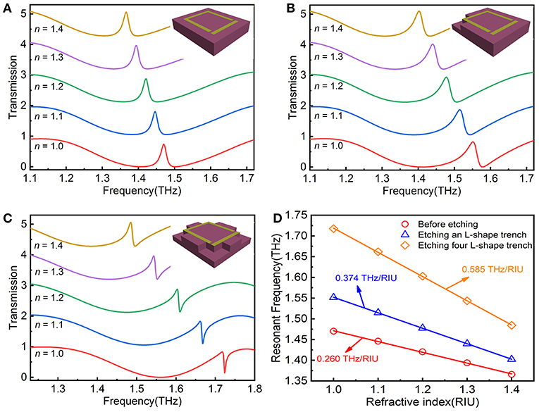
Figure 5. The transmission spectra of (A) the EIT metamaterial, (B) introducing an L-shape trench, and (C) the L-shape trenches etching in the four corners with different refraction index (n) from 1.0 to 1.4. (D) The variation of resonant frequency against refractive index of analyte and corresponding linear fitting curves.
In addition, we consider changing the etched shape from L-shape to hollow square to further expand the utilization rate of the electric field. Other parameters remain the same, only changing the etching shape, the transmission spectra of the metamaterial with different n from 1 to 1.4 are shown in Figure 6A. The resonant frequency of the EIT peak is larger compared to the L-shape etched shape due to the larger etched volume. Further, the expansion of the resonant frequency difference between the dipole and the quadrupole resulting in the shape of the EIT peak shows a Fano-type [39]. Figure 6B plots the resonant frequency vs. refractive index of analyte, the linear fit given by f = −0.719n + 2.523 shows a high degree of coincidence with a high R-Square of 0.9999. Hence, the sensitivity reaches 0.719 THz/RIU, higher than that etching four L-shape trenches and an increase of about 177% compared with no etching. By etching the trench with a hollow square, the excitation electric field outside the structure is utilized as much as possible.
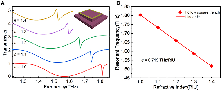
Figure 6. (A) The transmission spectra of etching a hollow square shape with different refraction index (n) from 1.0 to 1.4. (B) The variation frequency of EIT resonance vs. refractive index of analyte and corresponding linear fitting curve.
We have confirmed that the sensitivity can be enhanced by introducing a trench in the electric field excitation to strengthen light–matter interactions. However, the above considerations are based on the electric field outside the metamaterial structure, although the internal part is weak it still plays a role, therefore we consider etching entire substrate around the metamaterial unit cell as inset in Figure 7A. This means that the thickness of the analyte will reach 40 μm, the transmission spectra for various n plots in Figure 7A. The EIT peak presents a redshift significantly by refractive index changes, by fitting the EIT resonant frequency in Figure 7B, we obtain the linear fit as f = −0.826n + 2.705 with a high R-Square of 0.9997. The given sensitivity of 0.826 THz/RIU, an increase of ~2.2-fold compared to that without etching and the sensitivity is higher than the other two etching methods. It is also higher than those results reported previously in references [40, 41]. For example, dual-surface flexible sensor for detection of Ge (n = 4.0) thin films realized frequency shift of 89 GHz [40] and based on COC substrate realized a minimum thickness of 7 nm, and a thin-film of Ge is sensed on the metasurface with the frequency shift of 6 GHz [41]. Furthermore, the figure-of-merit (FOM) values increased from 14.2 to 49.2 compared with no etching through the following relation: FOM=S/FWHM. Etching the substrate to enhance light–matter interactions might provide a method to improve the sensitivity for other metamaterial sensors.
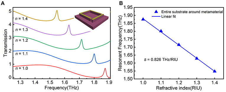
Figure 7. (A) The transmission spectra of etching the entire substrate around the metamaterial with different refraction index (n) from 1.0 to 1.4. (B) The variation of resonant frequency vs. refractive index of analyte and corresponding linear fitting curve.
In order to evaluate the influence of fabrication error on the performance of the proposed sensor, we consider adjusting the line width of the metal structure (w) and the coupling distance between the two sub-resonators (g) as a comparison, and the adjustment range is ± 1 μm. The etching method with the best sensing performance is selected, and the simulation result is shown in Figure 8. The transmission spectra under different conditions for various n plots is shown in Figures 8A–D, it maintains a fairly high consistency despite changes in w and g. From Figure 8E, except for the slight variation in the resonant frequency when w = 5 μm, the other three conditions are almost consistent. At the same time, their sensitivity is very close to each other, around 0.826 THz/RIU. Although the simulation results show that the processing error has a weak influence on the performance of the sensor, it still needs to be further verified by experiments. At present, the processing of metamaterials mainly uses photolithography and thermal evaporation technology [40, 41], and it has reached the precision requirements of the proposed metamaterial, which will be regarded as our future work.

Figure 8. The transmission spectra of etching the entire substrate around the metamaterial with different refraction index (n) from 1.0 to 1.4 under (A) w = 5 μm, (B) w = 7 μm, (C) g = 3 μm and (D) g = 5 μm. (E) The variation of resonant frequency vs. refractive index of analyte and corresponding linear fitting curve.
For further insight into the sensitivity for etching size, the relationship between the volume of etching and the increase in sensitivity should be analyzed. Since the depth of the three etching modes remains the same, the variation of sensitivity for different etching areas is plotted in Figure 9. These given areas of 2,576, 4,536, and 7,560 μm2 represent four L-shape trench modes, hollow square trench mode, and entire substrate around the metamaterial mode, respectively. The etching area enhancements mean more intense interactions between analyte and light resulting in the sensitivity increase monotonically until it reaches 0.826 THz/RIU. The sensitivity is improved immensely at the beginning of the etching owing to the enhancement of the electric field is concentrated in the corners of the CW and U-SRR (as shown in Figure 2D), while the weak electric field intensity in other parts of the structure leads to the gradual decrease of the sensitivity improvement and eventually reaches a maximum.
In summary, we demonstrated the excitation of sharp EIT resonance in a metasurface using two basic structures at THz frequencies. Through the surface electric field and charge distribution we further proved that the EIT resonance results from the coupling of dipole and quadrupole resonance. Due to the diffusivity of electric field distribution, more attention is paid to the part of the electric field that penetrates the substrate which is often neglected. A sensitivity of 0.826 THz/RIU is acquired by etching the entire substrate around the metamaterial, which is 2.2 times higher than the metamaterial without etching, meaning light–matter interactions have been enormously strengthened. Meanwhile, the FOM is as high as 49.2. In addition, with the expansion of the etching areas, the sensitivity increases progressively while the enhancement is decreased due to the relatively weak electric field of the etching area added later. Compared to placing the analyte directly on the metasurface, sufficient use of the excited electric field causes a higher sensitivity which can be achieved by substrate etching. Alongside this, the metamaterial, through customizing a trench for cells with specific sizes or forms, could potentially provide a platform for developing the next generation of biosensors for the precise identifying and supervising of biomolecules.
The raw data supporting the conclusions of this article will be made available by the authors, without undue reservation.
SZ put forward the initial idea and supervised the project. TL and YH further developed and confirmed the idea through analysis and simulations. TL and ML conducted data analysis and collection. YH and YZ performed image processing. SZ, YY, and JD provided methodology and resources. TL, YH, and SZ wrote the manuscript with inputs from all other authors. All authors discussed the results and commented on the manuscript.
The authors acknowledge the funding they received from the National Science Foundation of China (51675103), the Fujian Provincial Science and Technology Project (2019I0004), the State Key Laboratory of Mechanical Systems, and Vibration (MSV-2018-07), and the Shanghai Natural Sciences Fund (18ZR1414200).
The authors declare that the research was conducted in the absence of any commercial or financial relationships that could be construed as a potential conflict of interest.
1. Zhu WM, Liu AQ, Bourouina T, Tsai DP, Teng JH, Zhang XH, et al. Microelectromechanical Maltese-cross metamaterial with tunable terahertz anisotropy. Nat Commun. (2012) 3:1274. doi: 10.1038/ncomms2285
2. Manjappa M, Pitchappa P, Singh N, Wang N, Zheludev NI, Lee C, et al. Reconfigurable MEMS Fano metasurfaces with multiple-input-output states for logic operations at terahertz frequencies. Nat Commun. (2018) 9:4056. doi: 10.1038/s41467-018-06360-5
3. Huang Y, Zhong S, Shi T, Shen Y-c, Cui D. Terahertz plasmonic phase-jump manipulator for liquid sensing. Nanophotonics. (2020) 9:3011–21. doi: 10.1515/nanoph-2020-0247
4. Xu W, Xie L, Ying Y. Mechanisms and applications of terahertz metamaterial sensing: a review. Nanoscale. (2017) 9:13864–78. doi: 10.1039/C7NR03824K
5. Xiao S, Wang T, Liu T, Zhou C, Jiang X, Zhang J. Active metamaterials and metadevices: a review. J Phys D Appl Phys. (2020) 53:503002. doi: 10.1088/1361-6463/abaced
6. Lin Z, Xu Z, Liu P, Liang Z, Lin Y-S. Polarization-sensitive terahertz resonator using asymmetrical F-shaped metamaterial. Optics Laser Technol. (2020) 121:105826. doi: 10.1016/j.optlastec.2019.105826
7. Landy NI, Sajuyigbe S, Mock JJ, Smith DR, Padilla WJ. Perfect metamaterial absorber. Phys Rev Lett. (2008) 100:207402. doi: 10.1103/PhysRevLett.100.207402
8. Huang Y, Zhong S, Shi T, Shen YC, Cui D. Trapping waves with tunable prism-coupling terahertz metasurfaces absorber. Opt Express. (2019) 27:25647–55. doi: 10.1364/OE.27.025647
9. Chen M, Singh L, Xu N, Singh R, Zhang W, Xie L. Terahertz sensing of highly absorptive water-methanol mixtures with multiple resonances in metamaterials. Opt Express. (2017) 25:14089–97. doi: 10.1364/OE.25.014089
10. Zhang S, Genov DA, Wang Y, Liu M, Zhang X. Plasmon-induced transparency in metamaterials. Phys Rev Lett. (2008) 101:047401. doi: 10.1103/PhysRevLett.101.047401
11. Liu N, Langguth L, Weiss T, Kastel J, Fleischhauer M, Pfau T, et al. Plasmonic analogue of electromagnetically induced transparency at the Drude damping limit. Nat Mater. (2009) 8:758–62. doi: 10.1038/nmat2495
12. Gu J, Singh R, Liu X, Zhang X, Ma Y, Zhang S, et al. Active control of electromagnetically induced transparency analogue in terahertz metamaterials. Nat Commun. (2012) 3:1151. doi: 10.1038/ncomms2153
13. Singh R. Electromagnetically induced transparency in terahertz plasmonic metamaterials via dual excitation pathways of the dark mode. Appl Phys Lett. (2012) 100:131101. doi: 10.1063/1.3696306
14. Xiao S, Wang T, Liu T, Yan X, Li Z, Xu C. Active modulation of electromagnetically induced transparency analogue in terahertz hybrid metal-graphene metamaterials. Carbon. (2018) 126:271–8. doi: 10.1016/j.carbon.2017.10.035
15. Pitchappa P, Manjappa M, Ho CP, Singh R, Singh N, Lee C. Active control of electromagnetically induced transparency analog in terahertz MEMS metamaterial. Adv Opt Mater. (2016) 4:541–7. doi: 10.1002/adom.201500676
16. Singh R, Cao W, Al-Naib I, Cong L, Withayachumnankul W, Zhang W. Ultrasensitive terahertz sensing with high-Q Fano resonances in metasurfaces. Appl Phys Lett. (2014) 105:171101. doi: 10.1063/1.4895595
17. Rana G, Deshmukh P, Palkhivala S, Gupta A, Duttagupta SP, Prabhu SS, et al. Quadrupole-quadrupole interactions to control plasmon-induced transparency. Phys Rev Appl. (2018) 9:064015. doi: 10.1103/PhysRevApplied.9.064015
18. Yan X, Yang M, Zhang Z, Liang L, Wei D, Wang M, et al. The terahertz electromagnetically induced transparency-like metamaterials for sensitive biosensors in the detection of cancer cells. Biosens Bioelectron. (2019) 126:485–92. doi: 10.1016/j.bios.2018.11.014
19. Zhong S. Progress in terahertz nondestructive testing: a review. Front Mech Eng. (2018) 14:273–81. doi: 10.1007/s11465-018-0495-9
20. Huang Y, Zhong S, Shen YC, Yu Y, Cui D. Terahertz phase jumps for ultra-sensitive graphene plasmon sensing. Nanoscale. (2018) 10:22466–73. doi: 10.1039/C8NR08672A
21. Yang X, Zhao X, Yang K, Liu Y, Liu Y, Fu W, et al. Biomedical applications of terahertz spectroscopy and imaging. Trends Biotechnol. (2016) 34:810–24. doi: 10.1016/j.tibtech.2016.04.008
22. Geng Z, Zhang X, Fan Z, Lv X, Chen H. A route to terahertz metamaterial biosensor integrated with microfluidics for liver cancer biomarker testing in early stage. Sci Rep. (2017) 7:16378. doi: 10.1038/s41598-017-16762-y
23. Zhang Z, Ding H, Yan X, Liang L, Wei D, Wang M, et al. Sensitive detection of cancer cell apoptosis based on the non-bianisotropic metamaterials biosensors in terahertz frequency. Opt Mater Exp. (2018) 8:659–67. doi: 10.1364/OME.8.000659
24. Cui N, Guan M, Xu M, Fang W, Zhang Y, Zhao C, et al. Design and application of terahertz metamaterial sensor based on DSRRs in clinical quantitative detection of carcinoembryonic antigen. Opt Expr. (2020) 28:16834–44. doi: 10.1364/OE.393397
25. Zhang C, Liang L, Ding L, Jin B, Hou Y, Li C, et al. Label-free measurements on cell apoptosis using a terahertz metamaterial-based biosensor. Appl Phys Lett. (2016) 108:241105. doi: 10.1063/1.4954015
26. Gupta M, Singh R. Terahertz sensing with optimized Q/Veff metasurface cavities. Adv Opt Mater. (2020) 8:1902025. doi: 10.1002/adom.201902025
27. Hu X, Xu G, Wen L, Wang H, Zhao Y, Zhang Y, et al. Metamaterial absorber integrated microfluidic terahertz sensors. Laser Photonics Rev. (2016) 10:962–9. doi: 10.1002/lpor.201600064
28. Huang Y, Zhong S, Shi T, Shen YC, Cui D. HR-Si prism coupled tightly confined spoof surface plasmon polaritons mode for terahertz sensing. Opt Expr. (2019) 27:34067–78. doi: 10.1364/OE.27.034067
29. Liang L, Hu X, Wen L, Zhu Y, Yang X, Zhou J, et al. Unity integration of grating slot waveguide and microfluid for terahertz sensing. Laser Photonics Rev. (2018) 12:1800078. doi: 10.1002/lpor.201800078
30. Wu X, Quan B, Pan X, Xu X, Lu X, Gu C, et al. Alkanethiol-functionalized terahertz metamaterial as label-free, highly-sensitive and specific biosensor. Biosens Bioelectron. (2013) 42:626–31. doi: 10.1016/j.bios.2012.10.095
31. Saadeldin AS, Hameed MFO, Elkaramany EMA, Obayya SSA. Highly sensitive terahertz metamaterial sensor. IEEE Sensors J. (2019) 19:7993–99. doi: 10.1109/JSEN.2019.2918214
32. Ordal MA, Bell RJ, Alexander RW Jr, Long LL, Querry MR. Optical properties of fourteen metals in the infrared and far infrared: Al, Co, Cu, Au, Fe, Pb, Mo, Ni, Pd, Pt, Ag, Ti, V, and W. Appl Opt. (1985) 24:4493–99. doi 10.1364/AO.24.004493
33. Yang J, Wang P, Shi T, Gao S, Lu H, Yin Z, et al. Electrically tunable liquid crystal terahertz device based on double-layer plasmonic metamaterial. Opt Expr. (2019) 27:27039–45. doi: 10.1364/OE.27.027039
34. Zhou J, Koschny T, Soukoulis CM. Magnetic and electric excitations in split ring resonators. Opt Expr. (2007) 15:17881–90. doi 10.1364/OE.15.017881
35. Jin X, Park J, Zheng H, Lee S, LeeY, Rhee JY, et al. Highly-dispersive transparency at optical frequencies in planar metamaterials based on two-bright-mode coupling. (2011) 19:21652–57. doi 10.1364/OE.19.021652
36. Chen H, Zhang H, Liu M, Zhao Y, Guo X, Zhang Y. Realization of tunable plasmon-induced transparency by bright-bright mode coupling in Dirac semimetals. Opt Mater Expr. (2017) 7:3397–407. doi: 10.1364/OME.7.003397
37. Rockstuhl C, Lederer F. On the reinterpretation of resonances in split-ring-resonators at normal incidence. Opt Expr. (2006) 14:8827–36. doi 10.1364/OE.14.008827
38. Meng K, Park SJ, Burnett AD, Gill T, Wood CD, Rosamond M, et al. Increasing the sensitivity of terahertz split ring resonator metamaterials for dielectric sensing by localized substrate etching. Opt Express. (2019) 27:23164–72. doi: 10.1364/OE.27.023164
39. Singh R, Al-Naib IAI, Koch M, Zhang W. Sharp Fano resonances in THz metamaterials. Opt Expr. (2011) 19:6312–19. doi: 10.1364/OE.19.006312
40. Srivastava YK, Cong L, Singh R. Dual-surface flexible THz fano metasensor. Appl Phys Lett. (2017) 111:201101. doi: 10.1063/1.5000428
Keywords: terahertz sensing, substrate etching, electromagnetically induced transparency, metamaterials, sensitivity
Citation: Lin T, Huang Y, Zhong S, Luo M, Zhong Y, Yu Y and Ding J (2021) Sensing Enhancement of Electromagnetically Induced Transparency Effect in Terahertz Metamaterial by Substrate Etching. Front. Phys. 9:664864. doi: 10.3389/fphy.2021.664864
Received: 06 February 2021; Accepted: 06 April 2021;
Published: 24 May 2021.
Edited by:
Petra Granitzer, University of Graz, AustriaReviewed by:
Ranjan Singh, Nanyang Technological University, SingaporeCopyright © 2021 Lin, Huang, Zhong, Luo, Zhong, Yu and Ding. This is an open-access article distributed under the terms of the Creative Commons Attribution License (CC BY). The use, distribution or reproduction in other forums is permitted, provided the original author(s) and the copyright owner(s) are credited and that the original publication in this journal is cited, in accordance with accepted academic practice. No use, distribution or reproduction is permitted which does not comply with these terms.
*Correspondence: Shuncong Zhong, emhvbmdzaHVuY29uZ0Bob3RtYWlsLmNvbQ==
†These authors have contributed equally to this work and share first authorship
Disclaimer: All claims expressed in this article are solely those of the authors and do not necessarily represent those of their affiliated organizations, or those of the publisher, the editors and the reviewers. Any product that may be evaluated in this article or claim that may be made by its manufacturer is not guaranteed or endorsed by the publisher.
Research integrity at Frontiers

Learn more about the work of our research integrity team to safeguard the quality of each article we publish.