 Jun Xu
 Xiuqiang Yang2
 Fei Xiao
94% of researchers rate our articles as excellent or good
Learn more about the work of our research integrity team to safeguard the quality of each article we publish.
Find out more
ORIGINAL RESEARCH article
Front. Phys., 04 May 2021
Sec. Radiation Detectors and Imaging
Volume 9 - 2021 | https://doi.org/10.3389/fphy.2021.648072
This article is part of the Research TopicElectronics and Signal ProcessingView all 20 articles
In this paper, we present a substrate-suspended air cavity resonator featuring high-Q, consisting of five separate layers for confining electromagnetic energy. Its field distribution is analyzed in depth. By appropriately coupling the two resonators, a second-order Chebyshev bandpass frequency selection network is obtained, and design procedure is described. It forms a specific group delay response, in which high values can be achieved within a narrow frequency range around the center frequency. The frequency selection network has great flexibility in adjusting its magnitude and phase responses so that low insertion loss and high group delay are achieved simultaneously. This feature plays an important role in reducing phase noise when it is applied in a microwave oscillator. For demonstration, an X-band oscillator example was designed and fabricated. As the measured results show, it works at 11.16 GHz, and the phase noise at 100 KHz away from the oscillation frequency is as low as −120.68 dBc/Hz.
A microwave oscillator acts as a source of microwave signals, which have a significant impact on the performance of wireless communication system. Reducing phase noise of a microwave oscillator is still a hot topic. For this purpose, conventional microwave oscillators typically use frequency selection networks (FSNs) with a high quality factor, such as a metal cavity resonator or a dielectric resonator [1–4], which are mainly applied in a low frequency range. However, these FSNs have disadvantages, such as large size and difficulty in integration when they are applied in RF/Microwave frequency range.
As one option to reduce phase noise in microwave oscillators, to apply high Q-factor resonators or high group delay bandpass filters as FSNs in the form of microstrip receives much attention. For example [5], uses a high-selective filter with left- and right-hand characteristics to reduce the phase noise of an oscillator. In [6], an FSN based on a stubs loaded nested split-ring resonator obtains a group delay peak, which is effective for reducing the phase noise of an oscillator. In [7], a low phase noise oscillator based on the harmonic suppression of a stepped-impedance resonator (SIR) filter is proposed, and it achieves low phase noise for the sake of the excellent frequency selection and out-of-band rejection of the FSN. For the oscillators working in relatively high frequency range, substrate-integrated waveguide (SIW) structures and active FSNs are used for such specific purpose. For example, in [8], an active fourth-order elliptic filter with high group delay is used as the FSN in an oscillator to obtain excellent performance on phase noise. A low phase-noise X-band oscillator is implemented by using a dual-mode circular SIW resonator [9]. Based on an SIW resonator, a power splitter with fourth-order band-pass characteristics is implemented in [10], and a cross-coupling method is used to generate a transmission zero point in the upper sideband, which makes the power divider achieve a group delay peak. Due to the excellent frequency selection characteristics of the power divider, the oscillator in [10] achieves low phase noise. As demonstrated by the examples above, using a bandpass filter with a high group delay as a FSN is an effective way to reduce phase noise in a microwave oscillator.
In this paper, a novel substrate-suspended air cavity resonator (SSACR) topology is presented for high-Q operation. Its configuration is clearly displayed, and its electromagnetic property is analyzed in depth. The SSACR is mostly filled with air and has a higher height than a conventional SIW resonator does, so it could achieve a higher Q than the latter conventional SIW resonator does. Based on the SSACR, a second-order Chebyshev bandpass FSN is constructed, which is featured by high group delay within a narrow frequency range around the center frequency. This feature plays an important role in reducing phase noise when the FSN is applied in a X-band oscillator.
In this section, the configuration of the SSACR will be discussed. Then, its electromagnetic property is analyzed in depth. Finally, two SSACRs are coupled to form a second-order Chebyshev bandpass FSN, and the details of the design procedure are presented.
The configuration of the SSACR is shown in Figure 1. It consists of five layers: two metal layers and three substrate layers, among which Layers 1 and 5 are metal plates, and Layers 2, 3, and 4 utilize the same type of microstrip substrate. Layers 2 and 4 are hollowed out to form a rectangular air cavity which is surrounded by an array of metallic via holes. Within the upper and lower metallic surfaces of Layer 3, two rectangular patterns with the same size of that in Layers 2 and 4 are etched, respectively, which is also surrounded by an array of metallic via holes. In addition, within the upper surface of Layer 3, a metallic line acts as the transition between the microstrip line and the SSACR. Simultaneously, it also acts as the probe for exciting EM energy within the SSACR. Finally, all five layers are integrated tightly with screws to form the proposed SSACR. This specific configuration makes the SSACR effectively retain EM energy so that high Q can be obtained for the operation.
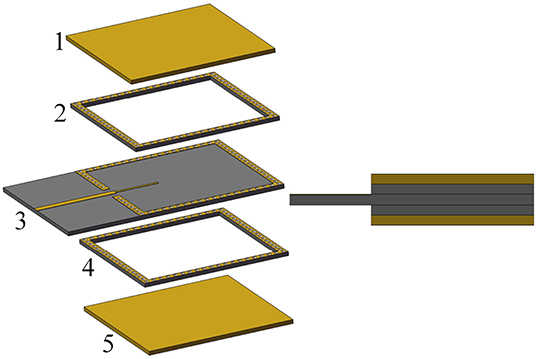
Figure 1. Configuration of the SSACR.
To facilitate practical application of the proposed SSACR, it is necessary to reveal its field distribution. Figure 2A shows a rectangular substrate-suspended waveguide. In essence, the SSACR can be considered as a rectangular substrate-suspended waveguide resonator. However, it is not easy to directly analyze the model in Figure 2A. Instead, we use an equivalent model, i.e., a rectangular waveguide filled with a uniform medium with the equivalent permittivity εeff to simplify direct analysis of the SSACR.
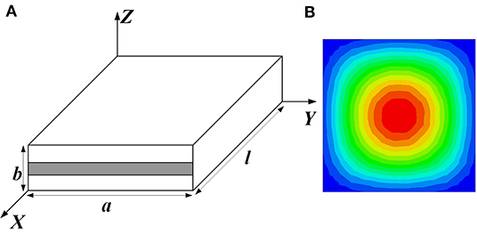
Figure 2. Simplified model of the SSACR. (A) Model; (B) Field distribution.
In the following, the effectiveness of such approach will be verified. The verification process includes the following several steps. First, a rectangular substrate-suspended waveguide is simulated to obtain the phase at the cut-off frequency. Secondly, the εeff of the rectangular waveguide filled with the uniform medium is calculated. For a resonator based on the rectangular waveguide filled with a uniform medium, the fundamental resonance frequency is calculated. If the fundamental resonance frequency of this rectangular waveguide resonator filled with a uniform medium is close to that of the SSACR, the equivalence between these two resonators is verified.
At first, the propagation constant β of the rectangular substrate-suspended waveguide is written as
where φ is the phase, and l is the length. In addition, the propagation constant of the rectangular waveguide filled with a uniform medium is
where μ0 and ε0 are the magnetic permeability and the dielectric constant in a vacuum, respectively. Then, εeff can be obtained from (1) and (2). For example, that of the TE10 mode is obtained as
Furthermore, the resonance condition of the rectangular waveguide resonator filled with uniform medium is
When n = 1, the electromagnetic field in the cavity is TE101 mode, and its resonance frequency can be obtained by (2), (3) and (4), i.e,
For demonstration, a substrate with relative permittivity of 3.66 and thickness of 0.508 mm is used in this paper. Based on that, an example of the SSACR is set up for EM analysis. The structural parameters are chosen as the following: a = 16.0 mm, b = 1.524 mm and l = 16.0 mm, respectively. The fundamental resonance frequency of the SSACR is 11.525 GHz. According to the verification process, first, a rectangular substrate-suspended waveguide is simulated to obtain the phase at the cut-off frequency. The simulation shows that the phase φ = 0.0418 rad at the cut-off frequency f c = 8.157 GHz. Then, according to (3), εeff = 1.32. The resonant frequency of the rectangular waveguide resonator filled with uniform medium is calculated as f = 11.535 GHz, using (5). Meanwhile, its field distribution is shown in Figure 2B, which is similar to that of the SSACR. Obviously, the simulated resonant frequency of the SSACR is very close to that of the rectangular waveguide resonator filled with a uniform medium. Therefore, the SSACR can be considered equivalent to a rectangular waveguide resonator filled with a uniform medium. The verification steps above can also be used to determine the structural dimensions of the SSACR at a particular frequency, which will be applied in the design of the FSN based on the SSACR.
The well-known Leeson model is written as
where L is the feedback loop insertion loss, F is the additional noise figure of the amplifier, K is the Boltzman constant, T is the ambient temperature, Pc is the oscillator output power, ωc is the flicker noise corner frequency, ωm is the deviation frequency, and τd is the feedback loop group delay, respectively, [11]. According to (6), both the insertion loss and group delay of the FSN have a great impact on the phase noise of an oscillator, between which compromise has to be made. Compared with a single resonator, a bandpass filter comprising more than one resonance might form a more flexible and complicated response to meet the requirements of an oscillator. The SSACR in the previous subsection could be used to construct a bandpass filter and then act as the FSN in microwave oscillator.
It should be noted that there is some difference between the performance of a conventional filter and that of the FSN used in oscillator. The latter aims to reduce low phase noise for an oscillator, and thus there is a specific requirement for its magnitude and phase responses simultaneously. In practice, the design procedure of a conventional bandpass filter can be applied, and then at least initial values can be obtained for starting. Through full-wave simulation, the performance of the FSN can be finally optimized to meet the requirements of microwave oscillator.
For example, we design a second-order Chebyshev bandpass FSN by coupling two SSACRs, as shown in Figure 3. In order to prevent electromagnetic leakage due to the gap between the substrates and the metal covers, two screw holes are arranged between two SSACRs. To apply the proposed FSN to the following X-band oscillator, the center frequency of the FSN is set at 11.0 GHz, and the bandwidth is 35 MHz. The physical mechanism of the FSN in Figure 3 can be described by the coupling topology in Figure 4. According to the design procedure of a conventional bandpass filter described in [12], the element parameters of the low-pass prototype are calculated as: g0 = 1.0000, g1 = 0.9635, g2 = 0.6581, and g3 = 1.4642, respectively. Then, the coupling coefficient M and the external Qe factor can be expressed as:
where FBW is the fractional bandwidth. For this case, Qe1 = 302.8, Qe2 = 302.8, MS, 1 = 0.0032, M1, 2 = 0.0040, and M2, L= 0.0032, respectively.
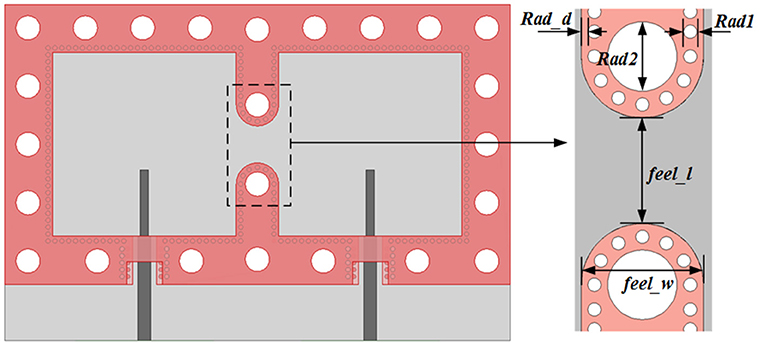
Figure 3. Top view of the second-order Chebyshev bandpass FSN using two SSACRs.
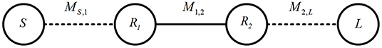
Figure 4. Coupling topology of the proposed FSN.
The model to extract actual external Qe-factor is shown in Figure 5. For narrowband operation, the dimensions of a single SSACR can be determined by (5). For this example, siw_x = siw_y = 16.2 mm. In order to avoid the influence of the screw holes on the electromagnetic field in the SSACR, some of the structural parameters in Figure 5 are: B_d = 1.0 mm, rad1 = 0.4 mm, rad2 = 2.1 mm, rad_d = 0.2 mm, and rad_d2 = 0.5 mm, respectively. For the sake of the external 50-ohm microstrip line being well matched to the SSACR, some structural parameters are IN_g = 2.0, feel_s1 = 0.5 mm, and feel_s2 = 1.0 mm, respectively.
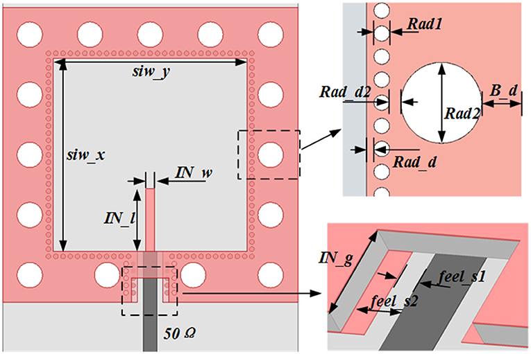
Figure 5. Extraction model for external Qe-factor.
Then, the external Qe-factor can be extracted by using the following formula [12].
where τs11(ω0) is the group delay of S11 at the resonant frequency ω0. In Figure 6, the relationship between some structural parameters and the external Qe-factor is depicted. Then, the desired value can be located on the curve so that the corresponding structural parameter can be determined. For this example, IN_l = 4.6 mm, and IN_w = 0.2 mm, respectively.
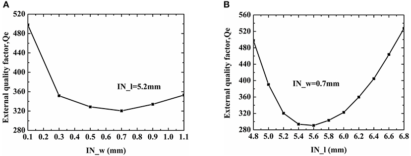
Figure 6. Relationship between some structural parameters and the external Qe factor. (A) Line width IN_w; (B) Line length IN_l.
To extract the coupling coefficient k, the following formula is used.
where f p1 and f p2 are the two resonant frequencies under weak coupling. In Figure 7, the relationship between the coupling gap feel_l and the coupling coefficient is depicted. For this example, when feel_l = 3.4 mm, k = 0.0030, which is very close to the desired value of 0.0032.
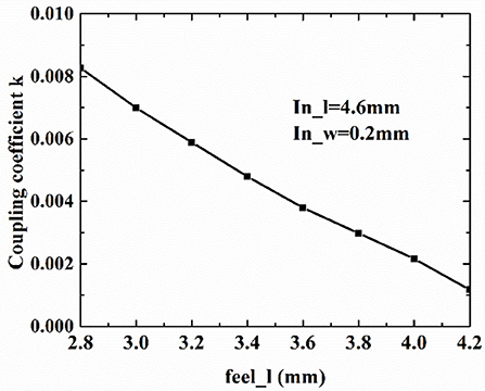
Figure 7. Relationship between the coupling gap feel_l and the coupling coefficient k.
Following the design procedure for a conventional bandpass filter, we can obtain a set of initial values for the proposed FSN in Figure 3. Then, according to oscillator requirement, the performance of the FSN is further optimized. Finally, IN_l = 5.2 mm, IN_w = 0.2 mm, and feel_l = 3.2 mm, respectively.
For this case, the simulated results are shown in Figure 8. Clearly, the second-order Chebyshev bandpass response is formed. Figure 8A depicts the magnitude response, and the minimum insertion loss at the center frequency is about 2.63 dB. Specially, high group delay is formed within a narrow range around the center frequency, as shown in Figure 8B. For example, the ones at 11.06, 11.08 and 11.10 GHz are 9.96, 8.37, and 9.98 ns, respectively. Such specific response is beneficial to frequency stability and phase noise reduction in the following oscillator design.
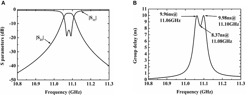
Figure 8. Simulation results of the FSN. (A) Magnitude response; (B) Group delay.
We apply the FSN based on the SSACRs into oscillator design in this section. In Figure 9, the oscillator schematic used in this paper is shown, which utilizes feedback type. It mainly consists of an amplifier, input and output matching network, a bandpass FSN, a phase shifter, and a 3 dB branch line coupler.
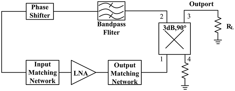
Figure 9. Oscillator schematic.
In practice, tolerance in fabrication or other minor factors will unfortunately result in actual phase deviation. In the worst case, it might lead to oscillation failure. Therefore, a phase shifter is required for phase compensation so that the whole loop phase at the oscillation frequency can satisfy oscillation condition. Here, a conventional reflective phase shifter is used, as shown in Figure 10, which consists of a branch line coupler and two identical grounded varactor diodes. The 3 dB branch line coupler acts as the output matching network of the oscillator to ensure that the output port of the oscillator is well-matched to 50 Ω. The actual phase shifter is shown in Figure 11. This design uses Skyworks Solutions' SMV2019-079LF varactor diode with a voltage range of 0 to 10 V and a variable capacitance range of 0.3 to 2.22 pF. The phase shifter operates at 11.08 GHz and uses the Rogers 4,350 substrate. The simulation results of the phase shifter are shown in Figure 12. The phase shifter has a phase variation range of −89.66° to 113.07°, and the insertion loss varies from 0.25 to 1.05 dB.
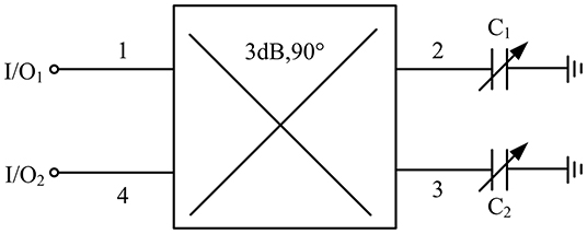
Figure 10. Reflective phase shifter schematic.
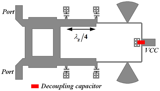
Figure 11. Actual phase shifter.
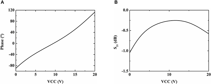
Figure 12. Simulated results of the phase shifter. (A) Phase vs. bias voltage VCC; (B) Insertion loss vs. bias voltage VCC.
For demonstration, a X-band oscillator example was designed and fabricated. The photo of the fabricated example is shown in Figure 13. An Infineon BFP840FEDS transistor is used as a low-noise amplifier. The example was measured by using Agilent Spectrum Analyzer and the measured results are presented in Figure 14. When the DC bias is 1.8 V, the current is 10.0 mA. The phase shifter operates at 4.0 V. The measured oscillation frequency is 11.16 GHz and the power is−1.6 dBm. The phase noise at 100 KHz away from the oscillation frequency is −120.68 dBc/Hz.
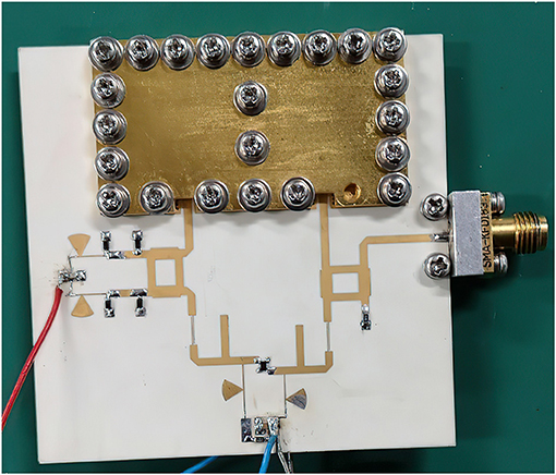
Figure 13. Photo of the fabricated X-band oscillator example.
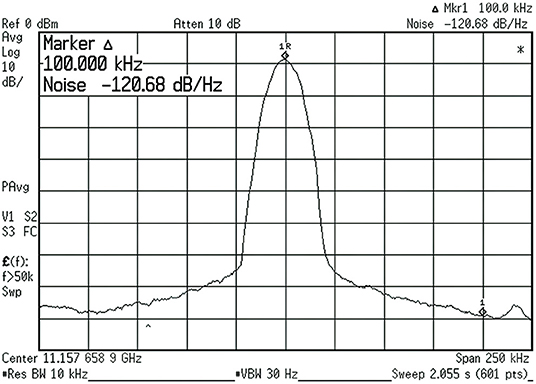
Figure 14. Measured phase noise of the fabricated X-band oscillator example.
In order to clearly demonstrate the advantages of the oscillator topology proposed in this paper, other works in the literature are compared, and the comparison results are listed in Table 1. The proposed oscillator features low phase noise.
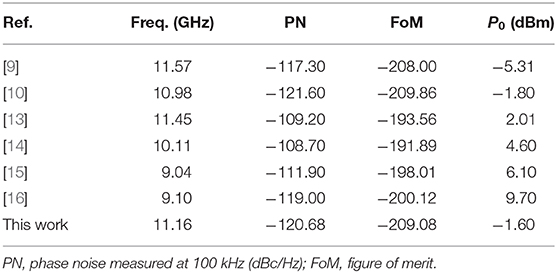
Table 1. Performance comparison.
In this paper, a substrate-suspended air cavity resonator (SSACR) topology is proposed for high-Q operation, and its physical mechanism is revealed clearly. By coupling two SSACRs, an FSN with the second-order Chebyshev bandpass response is formed and applied in a microwave oscillator. Owing to its flexibility in both magnitude and phase responses, it effectively reduces the phase noise of the oscillator. For demonstration, a X-band oscillator example was designed, fabricated, and measured. The measurement verifies the advantages of the proposed oscillator such as low phase noise.
The original contributions presented in the study are included in the article/supplementary material, further inquiries can be directed to the corresponding author/s.
JX made the design and measurement. DH, BC, and YC made a contribution to writing the paper. XY, LG, and FX focus on the whole research process and support the research work. All authors contributed to the article and approved the submitted version.
This work was supported by the National Natural Science Foundation of China (Project No. 61671111).
XY was employed by Chengdu Seekon Microwave Communications CO. Ltd.
The remaining authors declare that the research was conducted in the absence of any commercial or financial relationships that could be construed as a potential conflict of interest.
1. Jones R, Estrick V. Low phase noise dielectric resonator oscillator. In: 44th Annual Symposium on Frequency Control. Baltimore, MD (1990). p. 549–54. doi: 10.1109/FREQ.1990.177543
2. Uzawa K, Matsumoto K. Low noise microwave oscillator using ultra high-Q dielectric resonator. IEEE MTT-S Int. Microwave Symp Dig. (1991) 2:835–8. doi: 10.1109/MWSYM.1991.147136
3. Maffezzoni P, Zhang Z, Daniel L. A study of deterministic jitter in crystal oscillators. IEEE Trans Circuits Syst I. (2014) 61:1044–54. doi: 10.1109/TCSI.2013.2286028
4. Huang X, Liu D, Wang Y, Chen P, Fu W. 100-MHz low phase-noise microprocessor temperature compensated crystal oscillator. IEEE Trans Circuits Syst II Exp Briefs. (2015) 62:636–40. doi: 10.1109/TCSII.2015.2415652
5. Alburaikan A, Aqeeli M, Huang X-J, Hu Z-R. Low phase noise free-running oscillator based on high selectivity bandpass filter using composite right/left-handed transmission line. IEEE Microw Wireless Compon Lett. (2016) 26:273–5. doi: 10.1109/LMWC.2016.2537042
6. Cai Z, Liu Y, Tang X, Zhang T. A novel low phase noise oscillator using stubs loaded nested split-ring resonator. IEEE Microw Wireless Compon Lett. (2017) 27:386–8. doi: 10.1109/LMWC.2017.2678427
7. Tseng CH, Huang TS. Microwave voltage-controlled oscillator with harmonic-suppressed stepped-impedance-resonator filter. IEEE Trans Circ Systems II Exp Bri. (2017) 64:520–4. doi: 10.1109/TCSII.2016.2582855
8. Nick M, Mortazawi A. Low phase-noise planar oscillators based on low-noise active resonators. IEEE Trans Microw Theory Tech. (2010) 58:1133–9. doi: 10.1109/TMTT.2010.2045572
9. Huang W, Zhou J, Chen P. "An X-band low phase noise free-running oscillator using substrate integrated waveguide dual-mode bandpass filter with circular cavity. IEEE Microw Wireless Compon Lett. (2015) 25:40–42. doi: 10.1109/LMWC.2014.2363690
10. Zhang R, Zhou J, Yu Z, Yang B. A low phase noise feedback oscillator based on siw bandpass response power divider. IEEE Microwa Wireless Compon Lett. (2018) 28:153–5. doi: 10.1109/LMWC.2018.2791569
11. Leeson DB. A simple model of feedback oscillator noise spectrum. Proc IEEE. (1966) 54:329–30. doi: 10.1109/PROC.1966.4682
12. Hong J-S, Lancaster MJ. Microstrip Filter for RF/Microwave Application. New York, NY: Wiley (2001).
13. Chen Z, Hong W, Chen JX, Zhou J, Li LS. Low-phase noise oscillator utilizing high-Q active resonator based on substrate integrated waveguide technique. IET Microw Anten Propag. (2014) 8:137–44 doi: 10.1049/iet-map.2013.0380
14. Xu J, Cui Y, Xu Z, Guo J, Qian C, Li W. Low phase noise oscillator based on complementary split-ring resonators loaded quarter-mode circular SIW cavity. Electr Lett. (2017) 53:933–5. doi: 10.1049/el.2017.1829
15. Yang Z, Luo B, Dong J, Yang T. X-band low-phase noise oscillator employing substrate integrated waveguide dual-mode filter. Electr Lett. (2015) 51:494–5. doi: 10.1049/el.2014.4106
Keywords: group delay, microwave oscillator, phase noise, substrate-suspended air cavity resonator, filter
Citation: Xu J, Yang X, Huang D, Chen B, Chen Y, Guo L and Xiao F (2021) Substrate-Suspended Air Cavity Resonator and Its Application in Low Phase Noise Oscillator. Front. Phys. 9:648072. doi: 10.3389/fphy.2021.648072
Received: 31 December 2020; Accepted: 22 February 2021;
Published: 04 May 2021.
Edited by:
Gang Zhang, Nanjing Normal University, ChinaReviewed by:
Di Lu, Southern University of Science and Technology, ChinaCopyright © 2021 Xu, Yang, Huang, Chen, Chen, Guo and Xiao. This is an open-access article distributed under the terms of the Creative Commons Attribution License (CC BY). The use, distribution or reproduction in other forums is permitted, provided the original author(s) and the copyright owner(s) are credited and that the original publication in this journal is cited, in accordance with accepted academic practice. No use, distribution or reproduction is permitted which does not comply with these terms.
*Correspondence: Lei Guo, bGVpZ3VvQHVlc3RjLmVkdS5jbg==; Fei Xiao, ZnhpYW9AdWVzdGMuZWR1LmNu
Disclaimer: All claims expressed in this article are solely those of the authors and do not necessarily represent those of their affiliated organizations, or those of the publisher, the editors and the reviewers. Any product that may be evaluated in this article or claim that may be made by its manufacturer is not guaranteed or endorsed by the publisher.
Research integrity at Frontiers
Learn more about the work of our research integrity team to safeguard the quality of each article we publish.