 Pamela Vazquez-Vergara1,2
 Ulises Torres-Herrera1
 Gabriel A. Caballero-Robledo3
 Luis F. Olguin2*
 Eugenia Corvera Poiré1*
- 1Departamento de Física y Química Teórica, Facultad de Química, Universidad Nacional Autónoma de México, Ciudad de México, Mexico
- 2Laboratorio de Biofisicoquímica, Facultad de Química, Universidad Nacional Autónoma de México, Ciudad de México, Mexico
- 3Centro de Investigación y de Estudios Avanzados del IPN (Cinvestav), Apodaca, Mexico
Pulsatile flows of viscoelastic fluids are very important for lab-on-a-chip devices, because most biofluids have viscoelastic character and respond distinctively to different periodic forcing. They are also very important for organ-on-a-chip devices, where the natural mechanical conditions of cells are emulated. The resonance frequency of a fluid refers to a particular pulsatile periodicity of the pressure gradient that maximizes the amplitude of flow velocity. For viscoelastic fluids, this one has been measured experimentally only at macroscales, since fine tuning of rheological properties and system size is needed to observe it at microscales. We study the dynamics of a pulsatile (zero-mean flow) fluid slug formed by a viscoelastic fluid bounded by two air-fluid interfaces, in a microchannel of polymethyl methacrylate. We drive the fluid slug by a single-mode periodic pressure drop, imposed by a piezoactuator. We use three biocompatible polymer solutions of polyethylene oxide as model viscoelastic fluids, and find resonances. We propose a model accounting for surface tension and fluid viscoelasticity that has an excellent agreement with our experimental findings. It also provides an alternative way of measuring relaxation times. We validate the method with parameters reported in the literature for two of the solutions, and estimate the relaxation time for the third one.
1. Introduction
The study of oscillatory fluid flow at microscales has become relevant due to the increasing number of applications that use this type of motion. For example: chemical synthesis inside microfluidic channels [1], liquid-liquid extraction [2], mixing by oscillatory cross flow [3–7], cooling of microelectronic circuits by micro oscillating heat pipes [8], inertial focusing of particles of a few microns [9, 10], DNA elongation studies [11] and studies of oscillatory movement of liquid plugs displaced by air in microchannels as model pulmonary flows [12, 13].
Pulsatile flows of viscoelastic fluids are very important for most organ-on-a-chip devices, where the natural mechanical conditions of cells are emulated [14–17], since most natural processes occur at certain characteristic frequencies. The characterization of viscoelastic fluids under non-steady pressure forcing is also important for lab-on-a-chip clinical analysis of biofluids such as blood, mucus, or synovial fluid. The dynamics of polymeric viscoelastic solutions under pulsatile forcing in microchannels is an area of recent development [18]. Flow of these solutions is strongly influenced by chemical properties of the polymer, its molecular weight and ramifications, concentration, the nature of the solvent, temperature and pressure [19].
The fluid response to an oscillatory pressure gradient has often been described by the dynamic permeability, a theoretical linear response function that has been obtained for numerous confined fluids: Newtonian, Maxwellian and general linear viscoelastic fluids, in a wide range of confining geometries [20–27]. It has also been obtained theoretically for Newtonian and viscoelastic fluids confined in elastomeric materials at microscales [28, 29] and for compressible binary fluids [30]. A distinctive feature of the dynamic permeability, when elastic elements are present in the system, is that it presents resonances, which refer to particular pulsatile periodicities of the pressure gradient that maximize the amplitude of fluid velocity. Experimental observation of resonances consists of an increase of flow velocity amplitude at a specific frequency range of the driving pressure gradient, that maximizes the momentum transfer to the fluid. For single fluids, resonances have only been reported experimentally at macroscales [31, 32], since fine tuning of rheological properties and system size is needed to observe them at microscales, in a desired frequency range.
Recently, a model to study the dynamics of a pulsatile (zero-mean flow) fluid slug, consisting of a Newtonian fluid and two air-fluid interfaces, driven by a periodic pressure gradient in a rectangular microchannel, has been proposed [33]. In that model, a stress tensor for a Newtonian fluid, together with Laplace condition for the pressure jump at both sides of the curved air-fluid interfaces, has been considered. Analytical solution of the model showed, for relatively low frequencies, a monotonic increase with frequency of the magnitude of the dynamic permeability as well as the emergence of a resonant behavior, due to the presence of surface tension. Microfluidic experiments were designed and implemented to observe both the low-frequency dynamics and the resonance. The model was then validated against the experimental results and used as a proposed strategy to measure surface tension in dynamic situations.
There are different ways to impose oscillatory frequencies to a fluid inside a microchannel. By using syringe pumps, low frequencies of oscillation (below 10 Hz) are achieved [1]; in contrast, the use of high-speed valves and gas-pressurized fluids [3], mechanical motors [34], heating [35] or mechanical displacement of an air bubble [36] can increase the forcing frequency range to 10–1,000 Hz. Alternative possibilities to impose pulsatile forcing in this frequency interval are the use of a moving train of droplets [37] and the coupling of a loudspeaker diaphragm to a microfluidic chamber [4]. Finally, coupling the displacement of a piezoelectric to a fluid encompasses a wide range of forcing frequencies of the methods described previously [38].
There are several sophisticated theoretical models to study the rheological behavior of PEO solutions, in different ranges of concentration and molecular weights. Of particular importance are the Phan-Thien-Tanner (PTT) model [39, 40] and the Cross model [19]. They have been adequate to study several experimental conditions and driving forces where a complex rheological response, involving elongational and shear thinning effects, has been experimentally observed and theoretically reproduced. However, there is also experimental evidence that a Maxwellian model predicts correctly and accurately the behavior of small ejected, low molecular weight PEO (1x10⁶g/mol) droplet jets [41]. Moreover, within microchannels of constant sectional area, several works suggest that for spatially-uniform pressure gradients elongational and shear thinning effects, like the ones considered by the PTT and Cross models, are irrelevant [40, 42, 43]. Furthermore, despite the fact that viscoelastic fluids generally involve several relaxation times, many studies of fluids with complex rheological behavior often report a single dominant Maxwellian-like relaxation time, fitted from their experimental data, since the Maxwell model is used as an archetype in the field.
In this work, we perform experimental and theoretical studies of the dynamics of a pulsatile (zero-mean flow) microfluidic slug, formed by a viscoelastic fluid bounded by two air-fluid interfaces in a rectangular microchannel, and find resonances in the dynamic permeability. We have driven the fluid slug by a single-mode periodic pressure drop, imposed by a piezoactuator in the range from 0.5 to 200 Hz, managing to keep the amplitude of the dynamic pressure drop practically constant at all frequencies. We have determined the displacement of the viscoelastic slug by visualization of the oscillatory movement of air-fluid interfaces. We have used three biocompatible polymer solutions of polyethylene oxide (PEO), as model viscoelastic fluids, because the rheological behavior of PEO has been widely assessed [19, 44, 45]. We propose a linear model accounting for surface tension and fluid viscoelasticity, that has a good qualitative agreement with all of our experimental findings and a quantitative agreement for low pressure drops, where the linear theory is expected to describe the system. Such agreement provides an alternative way of measuring relaxation times. We validate the method against parameters reported in the literature for PEO of two different molecular weights: 1x10⁶g/mol (PEO1) and 5x10⁶g/mol (PEO5); and estimate the relaxation time for PEO of 8x10⁶g/mol (PEO8). This is of great relevance because relaxation times are sometimes difficult to measure for low polymer concentration in conventional rheometers [45–48].
The paper is organized as follows: section 2 describes the experimental procedure and the data analysis; section 3 describes the experimental results including resonances of the dynamic permeability; section 4 introduces a theoretical model for pulsatile viscoelastic slugs; section 5 compares experimental results for the dynamic permeability with predictions obtained from the theoretical model, it also introduces a proposal to measure relaxation times; section 6 summarizes the most important conclusions and perspectives.
2. Materials and Methods
2.1. Fluids
We use polyethylene oxide (Sigma-Aldrich) of three different average molecular weights: Mw = 1x10⁶ g/mol (PEO1); Mw = 5x10⁶ g/mol (PEO5) and Mw = 8x10⁶ g/mol (PEO8) to prepare solutions in deionized water at a fixed concentration of 0.1% (mass/volume). The dynamic viscosities, η, of the PEO solutions are: 1.72 mPa.s for PEO1 [41]; 4 mPa.s for PEO5 (approximated from a PEO4 solution at 0.1% (m/v) [19]), and 10 mPa·s for PEO8 [measured with an ARES (RSF III) Rheometer]. The three polymer solutions have the same surface tension, σ = 62 mN·m−1 [49].
2.2. Microfluidic Device
We machined a straight microchannel (37.48 ± 0.11 mm long, 1.00 ± 0.04 mm wide and 0.31 ± 0.05 mm deep) on a 2 mm-thick polymethyl methacrylate (PMMA) plate using a CNC machine (CNC3018). The channel was sealed with a second PMMA plate with four inlets (Figure 1) exposing both parts to volatilized chloroform for 4 min and pressing them by a pair of slides and clamps. The bonding was completed by sonication of the device in ethanol at 50 °C for 15 min [50, 51].
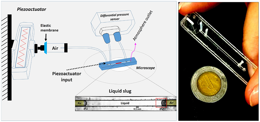
Figure 1. Experimental setup. The displacement of a liquid slug within the microchannel is driven by the periodical movement of the piezoelectric actuator compressing the air trapped between the elastic membrane and the left side of the fluid slug IF1. The position of one of the air-liquid interfaces, IF2, is visualized and recorded by means of an inverted microscope and a high-speed camera.
2.3. Experimental Setup
A piezoelectric actuator equipped with flexural hinges as an amplifier device (APF705, Thorlabs) was attached on one of its sides to an elastic membrane that covered a rigid polyethylene cylinder (15 mm long, 4.7 mm diameter). The opposite side of the cylinder has a seal with a tubing (0.51 mm ID, 1.19 mm OD and 1 cm long; Microbore PTFE Tubing, Cole-Parmer) inserted in the middle. The other end of the tubing was introduced into the first microdevice inlet. The movement of the actuator displaces the air in the cylinder and transduces an oscillatory movement to a slug of PEO solution (1.0 cm in length; 3.1 μL) situated in the middle of the microchannel (Figure 1). The oscillation frequency and amplitude of the piezoelectric motion was controlled by a multifunction data input/output device (USB-6351, National Instruments) and magnified by a Trek PZD350A High-Voltage amplifier (75–150 V). The pressure drop was measured by a differential pressure sensor (Honeywell 142PC01G) attached by PTFE tubing to the second and third inlets of the microfluidic channel. The fourth inlet was open to the atmosphere. The displacement of the liquid slug was visualized with the aid of an inverted microscope (DM IL LED, Leica) and the movement of the interface closest to the atmosphere outlet (IF2 in Figure 1) was recorded with a high-speed camera (Phantom Miro M110, Vision Research). Depending on the driving frequency, videos from 30 fps up to 3,000 fps were acquired after a 10 s stabilization period of cycling movement to ensure recording after transient states. The size of the fluid slug was verified after each measurement to confirm that no evaporation had occurred.
2.4. Data Analysis
The piezoactuator movement was adjusted by regulating the input voltage to keep the same reference pressure drop for all the range of frequencies studied. For each PEO solution, oscillatory pressure drops of four different amplitudes were used: 225, 450, 700, and 900 Pa, each in the frequency range from 0.5 to 200 Hz (Figure 2). The sinusoidal shape of pressure drop allowed us to fit a sinusoidal wave to obtain the amplitude of each signal.
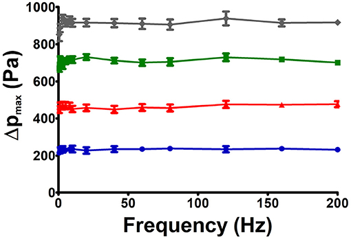
Figure 2. Four different pressure drops were studied for each PEO solution in the range from 0.5 to 200 Hz. The experimental amplitude of pressure drop was held almost constant at 225, 450, 700, or 900 Pa by adjusting the voltage input to the piezoelectric actuator. Data shown corresponds to a PEO8 0.1% solution.
The videos of the interface movement were analyzed using MATLAB utilities, that track the position of all interface points through time, then velocity was obtained by numerically differentiating position data.
To prove that the frequency imposed by the piezoactuator was consistent with the interface movement, Fourier transform of the pressure drop, interface displacement and interface velocity were performed. A dominant peak for the spectrum of all these signals was observed at the same frequency of oscillation of the piezoelectric transducer, indicating that the fluid slug follows the dynamics imposed by the piezoactuator (Figure 3).
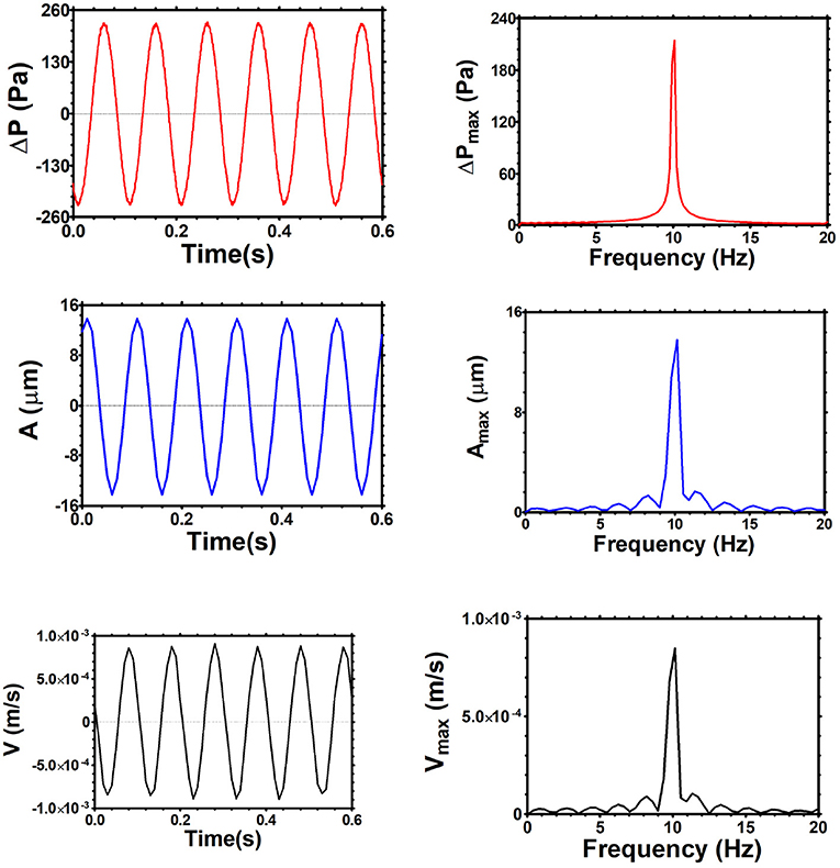
Figure 3. Left: pressure drop, interface displacement, and interface velocity as a function of time for the same experiment. Right: Fourier spectrum analysis of the corresponding quantities, showing that all of them have a dominant mode for their dynamics at 10 Hz. Data are for PEO5 0.1%, Δp = 225 Pa.
The dynamic contact angle of the interface was determined from video image analysis of the advancing and receding time lapses. The interface profile at every time, was fitted to a fourth-degree polynomial function. The fit reproduces very well the interface profile and was extrapolated to compute the contact angle at the wall. Figure 4 top illustrates the change in contact angle at five instants of an oscillation cycle. Figure 4 bottom shows the dynamic contact angle oscillation in time.
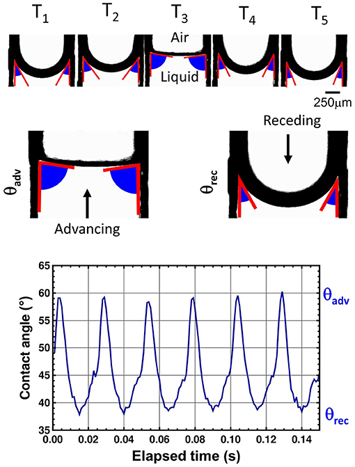
Figure 4. Top: Interface profile at 5 time instants (T1 − T5) during an oscillation cycle. Middle: The maximum contact angle is associated with the advancing stage of the cycle, while the minimum contact angle is associated with the receding stage of it. Bottom: Dynamic angle as a function of time obtained from the interface at the right of the fluid slug IF2. Data are for PEO8 oscillating at 40 Hz, driven by a Δpmax = 900 Pa.
3. Results
The air-fluid interfaces of the polymeric solutions display a characteristic curvature that flattens and bends in every oscillation cycle. This is illustrated in Figure 4 middle. In Figure 5, we show the air-fluid interface of PEO5 0.1% through an entire oscillation cycle at four different frequencies. A maximum amplitude of the displacement, Amax, for this experiment occurs at 40 Hz. Peak-to-peak amplitude of the displacement is highlighted in red so the frequency dependent behavior can be assessed visually. It is clear that the neighboring smaller or larger frequencies display a smaller displacement.
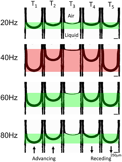
Figure 5. Interface profiles at 5 time instants (T1 − T5) during an oscillation cycle for four different frequencies, illustrating that the maximum amplitude of the displacement is a non-monotonic function of frequency. T1 represents the minimum position and T3 the maximum position of the cycle. Data are for PEO5 oscillating in the range [20–80] Hz, driven by a Δpmax = 700 Pa.
By changing the frequency but keeping constant the amplitude of pressure drop driving the movement, a clear non-monotonic behavior of the amplitude of the interface displacement is observed for different driving frequencies, even for the PEO of lowest molecular weight. Top panels in Figure 6 show that the highest displacement for each fluid increases in magnitude as the imposed pressure rises, which is an expected result for an increasing driving force. The maximum interface movement is observed for PEO1, the fluid with the smallest molecular weight and viscosity. The interface velocity, at the center of the microchannel, as a function of the oscillating frequency shows an asymmetric bell-shape curve for each imposed pressure (Figure 6 middle panels). As expected, the maximum velocity amplitude rises as the pressure increases for all PEO solutions. The peak of each curve is the resonance frequency, meaning that at this frequency the amplitude of flow velocity is maximum in the frequency range studied. A non-trivial effect is observed in which the resonance frequency decreases with an increasing pressure drop. This is part of the non-linear behavior of the system response. Since we are driving the system with a one-mode pressure drop, we expect that, at least in the linear regime, the amplitude of the interface velocity would be given by the maximum amplitude of the interface displacement multiplied by its frequency. For this reason, the resonances observed in velocity have higher frequencies than those obtained for the amplitude of interface position.
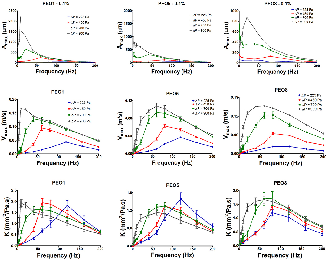
Figure 6. Maximum amplitude of displacement, maximum amplitude of velocity and modulus of dynamic permeability, as a function of driving frequency for the three PEO polymeric solutions and 4 different maximum amplitudes of the driving pressure drop.
We also analyzed the dynamic permeability of each polymer solution as a function of frequency and amplitude of pressure drop (Figure 6 bottom panels). We present an operational definition of the amplitude of the local dynamic permeability at the center of the channel, as the ratio between the maximum amplitude of the velocity at the center of the channel, divided by the pressure gradient—given by the quotient of pressure drop, Δp, and slug length, L,—that is,
Derivation of Equation (1) will be given in section 4 Model for small pressure drop values; however, we will use this operational definition for all pressure drops studied, since it is a convenient way to cancel out the small differences in pressure drop amplitude for the different frequencies tested (see Figure 2). In this sense, K can be interpreted as a velocity rescaled by a pressure gradient. Accordingly, in the bottom panels of Figure 6, we observe that the resonance frequencies of the local permeability are roughly the same as those obtained for velocity data. Also, as pressure drop increases, the resonance frequency of the permeability decreases. This effect is more pronounced for low molecular weights. For the dynamic permeability value at resonance, there is no clear trend when the amplitude of the pressure drop changes. For details and graphs describing this behavior, see Supplementary Material.
Regarding the dynamics of the contact angle, we found that advancing angles are larger than receding ones. As an example, Figure 7 shows the dynamic angles obtained when the amplitude of pressure drop is 225 Pa. It has been reported in the literature that, when velocity increases, the advancing angle augments and the receding angle decreases, so a larger difference between them should be observed [52–55]. The difference of advancing and receding angles, Δθ = θadv − θrec (sometimes called contact angle hysteresis [52]), is shown as a function of frequency in Figure 8. For a single-mode oscillatory flow, the fluid velocity increases with frequency up to the resonance and then decreases. We can observe that the same trend exists for Δθ as a function of frequency. The fact that the dynamic contact angle difference is affected by the interface velocity, has previously been reported for capillary numbers close to the ones of our experiments (Ca = 10−5 to 10−3) [53, 55]. This phenomenon is attributed to surface roughness and chemical heterogeneity [56, 57], but there is an influence of the fluid rheological properties, like shear thinning or elasticity [53]. In our slug, an important component of elasticity is given by the presence of two interfaces.
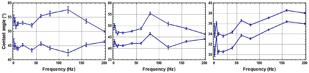
Figure 7. Contact angle as a function of frequency. For each plot, the upper line corresponds to the advancing angle and the lower line corresponds to the receding angle. Left: PEO1. Center: PEO5. Right: PEO8. The difference between advancing and receding angle diminish as the molecular weight is higher.
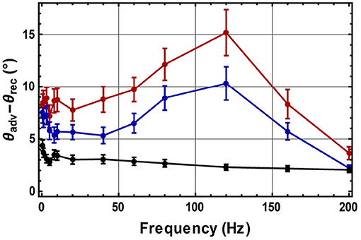
Figure 8. Contact angle hysteresis as a function of frequency for the three PEO solutions with different molecular weights for Δp = 225 Pa (red line: PEO1; blue line: PEO5; black line: PEO8).
4. Model
In order to explain theoretically our experimental results, we build up a model containing two basic features: the viscoelastic character of the fluid and the elastic character of interfaces. The interplay between these two elasticities will lead to a complex behavior, the simpler the rheology of the viscoelastic fluid, the easier the understanding of the physical interaction. Because of this, we present a model for the uniaxial dynamics of a viscoelastic slug, taking into account the presence of interfaces and the viscoelastic character of a single-relaxation-time fluid, that could be extended to models containing more characteristic times. We build up a model for the dynamics of viscoelastic slugs over a model presented for the dynamics of a Newtonian slug [33].
A study of a pulsatile fluid slug consisting of a Newtonian fluid and two air-fluid interfaces driven by a periodic pressure gradient, has been recently proposed and validated [33]. In that model, a stress tensor for a Newtonian fluid of the form τ = −η∇v, together with Laplace condition for the pressure jump at both sides of the air-fluid curved interfaces, Δp = Δpdriving + σκ1 + σκ2, has been considered. In these expressions, η is the fluid viscosity, v is the axial fluid velocity, σ is the surface tension of the air-fluid interfaces, κ1 and κ2 are the left and right hand side curvatures, respectively, and Δpdriving is the pressure drop external to the fluid slug (on the air side). The dynamics for such Newtonian slugs is described by an integro-differential equation in space and time, which, in frequency domain, can be written as a simple equation, differential in space and algebraic in frequency, that reads:
where ω denotes angular frequency, ρ is the fluid density, L is the length of the fluid slug, and and denote Fourier transforms of velocity and pressure, respectively. This equation incorporates momentum conservation, the stress tensor for a Newtonian fluid, Laplace equation for the pressure jump at the interfaces, an approximation of interface curvatures as concavities, and continuity of velocities at both interfaces. This model has given a correct description of the experimental dynamics of a water slug and of a 70% glycerol solution in water slug, when interfacial curvatures are considered to be a response to a dynamic external pressure gradient Δpdriving/L. Details of the derivation of Equation (2) can be seen in [33].
A Newtonian slug stress tensor, that integrates stresses of the Newtonian fluid and the interfaces, of the form
substituted in the linearized momentum conservation equation for uniaxial flow in the x direction,
gives exactly Equation (2) for the dynamics of a Newtonian slug. A stress tensor of the form (3) for a material consisting of a volume of fluid and two air-fluid interfaces, has not been introduced in the literature, to the best of our knowledge, since classical treatments describe both fluid phases and apply boundary conditions at air-fluid interfaces, rather than describing the system fluid-interfaces as a composite material. Vazquez-Vergara et al. [33] together with discussion in the previous paragraph, show that introduction of a slug stress tensor, as the one in Equation (3), is a consistent approach to describe the zero-mean flow, linear pulsatile dynamics of Newtonian slugs.
Viscoelastic fluids might involve, in general, several relaxation times. The coupling of such times with the characteristic time given by the presence of interfaces, is expected to lead to a complex dynamics of viscoelastic slugs. To understand such coupling, we start by introducing the simplest model of a viscoelastic slug, consisting of a volume of linear Maxwellian fluid, that has a single relaxation time, and two air-fluid interfaces, with surface tension σ.1 We propose the following expression for the viscoelastic slug stress tensor:
where the parameter tr is the Maxwell relaxation time. Equation (5) reduces to the constitutive equation of a Newtonian slug (Equation 3) in the limit tr → 0, and reduces to the Maxwell model in the absence of interfaces [58], that is, in the limit σ → 0. Along with the previous consistency proofs, experimental validity of the model given by Equation (5) must be demonstrated.
When the stress tensor (Equation 5) is substituted in the momentum conservation equation (Equation 4), we can obtain an equation for the dynamics of a viscoelastic slug,
Solution of Equation (6) subject to no-slip boundary conditions, for flow in a rectangular microchannel whose plates are separated by a distance 2l, gives a linear relation between velocity and pressure drop in frequency domain, that is,
where z is the coordinate perpendicular to the plates. The complex local dynamic permeability, K(z, ω), is given by
This linear relation is expected to coincide with experimental results, for low values of the pressure drop, where K(z, ω) is independent of the amplitude of the pulsatile forcing.
It is worth noticing that Equations (7) and (8), which are the solution for the dynamics of a Maxwellian slug given by our model, are consistent with the pulsatile solution of the linear Maxwell model for a single fluid in a rectangular cell in the limit of zero surface tension given in [26] (equivalent to the solution in [23, 24, 59] in the cylindrical case).
Expressions (7) and (8) are valid for general periodic time-dependent pressure drops, consisting of an arbitrary number of sinusoidal modes. In particular, for a one-mode driving pressure drop of frequency ω0, it can be shown that, in time domain, the amplitude of the velocity at the center of the cell, vmax, is related to the amplitude of the pressure drop, Δpmax, as
which is in agreement with the operational definition of K, used to compute the permeability from experimental data in Equation (1).
Our model has been deliberately developed for zero-mean pulsatile flows, due to the oscillatory nature of our experimental driving force. It therefore cannot be used to model fronts in imbibition-like systems, where the pressure drop has always the same sign and the interface curvature is due to wetting. In our case, curvature effects due to wetting cancel out since they have opposite signs on the left and right side interfaces [33], and the dynamics of the slug will be governed by the instantaneous interfacial curvatures caused by pulsatile forcing.
5. Comparison with Experimental Results
We compare the experimental results for K at low-amplitude pressure drops (225 Pa) from Figure 6 with K(0, ω0) derived from the linear model developed in the previous section. For the figures, we simply use K to denote the local dynamic permeability at the center of the microchannel. Figure 9 shows experimental and theoretical predictions of K as a function of the driving frequency for three PEOs. A log-log scale has been used to highlight the tendency of low frequency data.
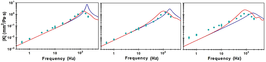
Figure 9. Comparison of theoretical (red and blue lines) and experimental results (green dots) for dynamic permeability for PEO solutions at 225 Pa of: (left) PEO1 solution; (middle) PEO5 solution; (right) PEO8 solution.
Figure 9 left shows, with green dots, the permeability K obtained from experimental data for PEO1. With a red continuous line, it shows the theoretical permeability, as predicted by our model for a Maxwellian slug, obtained from Equation (8) with z = 0 and a relaxation time, tr = 1.78 ms, reported as Maxwellian in the literature [41]. As reference, we have also plotted, in a blue continuous line, the theoretical permeability for a Newtonian slug. As Figure 9 left shows, the agreement between experimental data and theoretical prediction for a slug of a viscoelastic fluid obeying Equation (8) is excellent, both, at low frequencies and around resonance; Figure 9 middle shows equivalent curves for PEO5. Since the relaxation time, at the concentration used in our experiments, is not reported in the literature, we took one reported for PEO4, as surrogate [19]. The agreement between the green dots, obtained from experimental data, and the red line predicted by our model, is very good, both, at small frequencies and around resonance, despite the fact that the relaxation time used was obtained from a fit to a Cross model [19, 60].
Before discussing Figure 9 right for PEO8, for which there is no relaxation time reported in the literature, at the desired concentration, we will discuss the theoretical behavior of the resonance frequency, in terms of characteristic frequencies of the system.
We can define three characteristic frequencies of the system that depend on viscosity, η, surface tension, σ, relaxation time, tr, and system's geometry, l (half the microchannel thickness), as
In terms of these frequencies, the argument of the cosine term, Al, in Equation (8), can be written as
We find two different regimes for the resonance frequency. For ωrelax ≪ ωη, the resonance frequency, ωres, is given by
while for ωrelax ≫ ωη, it is given by
The resonance frequency, with the proper scaling to make the second of these regimes collapse, is given in Figure 10.
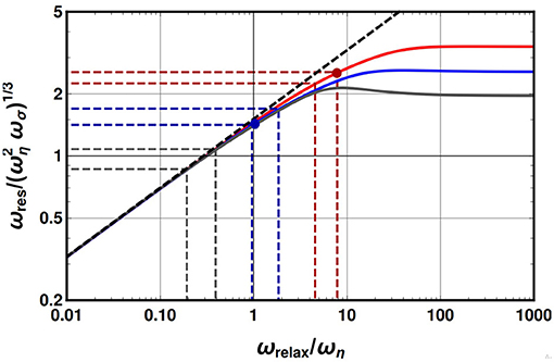
Figure 10. Illustration for the way of estimating the value of relaxation time (through ωrelax) by visual estimation of the resonance frequency, and its corresponding error bars. The theoretical model predicts a relation between resonance frequency and relaxation frequency that can be exploited to validate or estimate relaxation times. We have used PEO1 solution (red dashed lines), and PEO5 solution (blue dashed lines) to validate the method. Then we have used the method to estimate the relaxation of the PEO8 solution, from its experimental resonance (gray dashed lines). Red and blue intervals, marked with dashed lines, are in agreement with theoretical data of resonance frequency and relaxation times (placed as a circle red dot) for PEO1 and (placed as a circle blue dot) for PEO5. Black dashed line represents an approximated relation for ωres in Equation (13). Continuous lines are exact results for resonance, obtained by numerical means.
We have found numerically the maximum of the local dynamic permeability in Equation (8) using characteristic values of ωη and ωσ for each of the three PEO solutions employed in the experiments. We have plotted the resonance frequency as a function of the independent variable ωrelax/ωη. The red curve corresponds to PEO1, the blue curve to PEO5 and the gray curve to PEO8. Red and blue dots over the curves (for PEO1 and for PEO5, respectively) represent pairs , in the corresponding rescaled units of the graph, where is the theoretical resonance obtained using a relaxation time from the literature.
Our resonance curves in Figure 10 could serve “as a rheometer” to validate or estimate viscoelastic relaxation times. Such a procedure is schematized with horizontal dashed lines in Figure 10, which relate a reasonable resonance frequency range—obtained by visual inspection of Figure 9—, with a range of possible relaxation times, obtained from the vertical dashed lines, through the theoretical curve in Figure 10. To validate our method, we have estimated that the resonance frequency for PEO1, is in the range [120:136] Hz, and in the range [100:120] Hz for PEO5. As Table 1 shows, the range of relaxation times estimated by the theory—from measurement of the experimental resonance frequency—are in agreement with the values for the relaxation time reported in the literature. We consider that, as a proof of concept, this validates our method for estimating relaxation times of single-relaxation-time viscoelastic fluids. Accordingly, we estimate from Figure 9 that, for PEO8, the resonance frequency is in the range [80:100] Hz, and estimate that the relaxation time would be in the range [6.8:14.8] ms. Even though this range is wide, when considering a value in the middle of this range, we obtain the red curve in Figure 9 for the dynamic permeability,which, despite being less accurate than the ones for the lower molecular weight polymers, still gives a reasonable agreement for both, the tendency of the experimental permeability at low frequencies, and the region around resonance. It is important to note that the relaxation times obtained with our method follow the trend that, the larger the molecular weight of PEO, the larger the relaxation time. This is in qualitative agreement with global trends observed in literature for a vast range of concentrations and molecular weights in PEO aqueous solutions [19, 41, 61]. Our method promises to be valuable for low molecular weight polymers, for which relaxation times are difficult to obtain experimentally by conventional means. For high molecular weight polymers, more sophisticated models, including shear thinning, might result necessary to describe the dynamics and to obtain rheological parameters from it, as it happens for high concentrations of low molecular weight polymer solutions [19, 45]. It is worth mentioning that the size of the fluid slug can be experimentally adjusted to fall in the range where the approximated black dashed line in Figure 10 is valid, that is, whenever it agrees with the exact value of resonance frequency, given by the continuous lines; at such regime, there is a simple analytical relation between resonance frequency and relaxation time, and the indirect determination of relaxation times could be carried out easily using Equation (13). In contrast, the plateau observed for each continuous line on the right side of Figure 10, corresponds to the regime where the resonance frequency is given by Equation (12), when the relaxation time is not relevant. The curves differ from each other due to their viscous frequency, ωη.
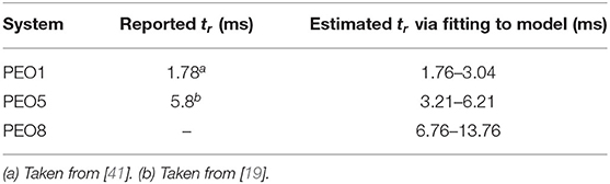
Table 1. Comparison between reported values in the literature of viscoelastic relaxation time and the range estimated by the theoretical model via the experimental resonance.
Our theory is also able to predict the contact angle, given an initial shape of the interface. Several models for front dynamics in the literature establish a difference between a static contact angle at equilibrium situations, and the angle observed due to an imbibition-like front dynamics, where the pressure gradient has always the same sign, this is typically called a dynamic contact angle. In addition to such descriptions, recent studies have dealt with a different time-varying dynamic contact angle, which is affected not only by imbibition phenomena but also by oscillatory driving forces [62]. This is the case of our dynamic contact angle. We explain in a nutshell how do we compute dynamic contact angles from our theoretical model: our differential equation gives the slug velocity v(z, t) as a function of pressure drop. Since interface shape, u(z, t), and velocity are related through ∂u/∂t = v, once the velocity v(z, t) is known, we can integrate this equation to obtain u(z, t) = ∫v(z, t)dt + u0(z), where u0(z) is an integration constant which gives the interface profile at rest (or, equivalently, at very high frequencies). Once the interfacial profile is known in time, the arctangent of its slope close to the wall gives the dynamic contact angle.
It is worth mentioning that our experiments measure an angle along the channel width, not along the channel height, which is the dimension modeled in Equation (6). So, it is necessary to find out a relation between the angles measured in both planes. We follow Tabeling results [63] on steady flow where the relation between the slope of flow velocity at the channel walls in both planes obeys a linear relation of the form
where m is a factor that only depends on the aspect ratio W/2l (see Figure 11 left). Since for a single-mode oscillatory flow, interface shapes and velocity are linearly related through the driving frequency, that is, ω0, as v(y, z, t) = ω0u(y, z, t), an equivalent relation can be proposed for interfacial profiles, u, as
This geometrical relation between the slope at both confining dimensions is illustrated in Figure 11 left. The dynamics of both angles is illustrated in Figure 11 right.
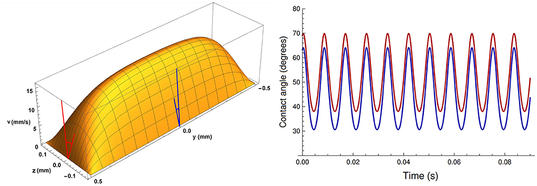
Figure 11. Left: Illustration of an instantaneous velocity profile in a cross section of a rectangular microchannel, computed theoretically following [63]. Right: Illustration of the time behavior of the angle (given by the arctan of the slope) along the channel width (red), and along the channel height (blue), for a channel whose width is three times its height.
With the correction explained above, the experimentally obtained contact angles are compared to the ones predicted by our model. This is shown in Figure 12. We find that the contact angle predicted by the theory is larger than the one obtained from experiments; however, our theory correctly predicts the phase difference between the angle and the pressure gradient.
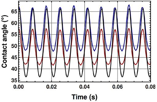
Figure 12. Comparison between predicted and measured contact angles for a slug of PEO1 solution pulsated at frequency of 120 Hz, and a pressure drop amplitude of 225 Pa. Blue and red lines correspond to the contact angle, obtained from experimental measurements, at the left and right walls of the microchannel, respectively; black line corresponds to the theoretical prediction. Agreement between theoretical and experimental results is noticeable, particularly because their oscillation is in phase.
A model for single Maxwellian fluids accounting for channel width and height, has found that the effect of the second confining dimension is relevant only at high frequencies [64]. We therefore consider that if such analysis were extended to Maxwellian slugs, it would not affect the conclusions regarding resonances and dynamic permeabilities presented in this work.
6. Conclusions and Perspectives
We have made a thorough experimental study of the dynamic behavior of pulsatile fluid slugs made by three biocompatible viscoelastic fluids [65]. We have studied their responses in a wide frequency range, from [0.5:200] Hz, at four different amplitudes of the pressure drop, which have been maintained practically constant in all the frequency range. We have chosen the dynamic permeability as a parameter to characterize the fluid dynamics since, in the regime where flow and pressure drop are linearly related, it can be analytically demonstrated that it is a response function of the system to a pulsatile pressure drop. At higher pressure drops, it is a convenient way to represent a rescaled velocity, which cancels, to linear order, the small differences in pressure drop amplitude applied at different frequencies. We have found that the permeability of the three viscoelastic slugs present resonances, that is, a special frequency range of the oscillatory pressure gradient that maximizes the amplitude of flow velocity.
We have also developed a continuum-mechanics linear model of viscoelastic slugs, containing both, the elasticity of the fluid and the elasticity given by air-fluid interfaces, through surface tension. The slug model gives excellent agreement with our experimental results at low-amplitude pressure drops. Such an agreement was a necessary condition for model validation. The dynamic permeability at all frequencies coincides very well for PEO1 and PEO5 solutions, both, at small frequencies and at resonance. Coincidence of experimental and theoretical resonances provides an alternative strategy for measuring relaxation times. We validated this strategy with relaxation times reported in the literature for PEO1 and PEO5 solutions, and estimated the relaxation time for PEO8. With such estimation, the dynamic permeability for PEO8 gives the correct slope as a function of frequency (in log-log scale), at small frequencies, and gives a very good agreement around resonance. It is worth mentioning that viscoelastic fluids, in general, have several relaxation times. If one uses a single-relaxation-time model, this one should correspond approximately to the larger characteristic time experimentally observed. Our model for viscoelastic slugs could be extended, in a more or less straightforward manner, to models with several relaxation times. The problem for validation in that case, would be the lack of experimental information in the literature of the several relaxation times reported for a specific molecular weight and a specific concentration of a polymer solution obeying a specific model.
Finally, we have compared the dynamics of the contact angle, and found that theory and experiments predict similar amplitudes and exactly the same phase shift with respect to the oscillatory pressure drop. In our experiments, the interface motion is negligible close to the wall, when compared to the motion of the interface at the center of the channel. For this reason, we have not included slip in our model and the contact line displacement is not a concern for our relatively small-amplitude pressure drops.
This is the first time that experimental resonances of the dynamic permeability of viscoelastic fluids, confined at microscales, are reported in the literature. Our results are relevant for flow and shear rate control, with potential applications to many systems, like organ-on-a-chip devices where the natural mechanical conditions of cells are emulated [14–17]; and biofluids, which are typically viscoelastic, are present. Our results could also be useful to study how cells would respond to different imposed, non-physiological, external stresses [66–71].
Data Availability Statement
The raw data supporting the conclusions of this article will be made available by the authors, without undue reservation.
Author Contributions
PV-V performed the experiments. UT-H and ECP developed the analytical model and performed analytical calculations. PV-V and UT-H carried out data curation. GC-R designed the preliminary experimental settings and performed the preliminary experiments. PV-V and LO designed the final experimental setting. LO directed the experiments. PV-V, LO, and ECP wrote the original draft. GC-R, LO, and ECP did the funding acquisition. LO and ECP supervised the investigation. ECP conceptualized the project and coordinated the work. All authors gave final approval for publication.
Funding
PV-V acknowledges CONACyT (Mexico) for 2-year postdoctoral funding through Project 219584. UT-H acknowledges financial support from CONACyT (Mexico) through Fellowship No. 589015. GC-R acknowledges financial support from CINVESTAV (Mexico) for open access expenses. LO acknowledges financial support from Faculty of Chemistry, UNAM, through PAIP Project 5000-9023. ECP acknowledges financial support from Faculty of Chemistry, UNAM, through PAIP Project 5000-9011. ECP acknowledges financial support from CONACyT (Mexico), through project 219584. The authors acknowledge financial support from DGAPA, UNAM, through PAPIIT Projects IT203318 and IN113421.
Conflict of Interest
The authors declare that the research was conducted in the absence of any commercial or financial relationships that could be construed as a potential conflict of interest.
Acknowledgments
The authors thank Pablo E. Guevara-Pantoja and Patricia Cerda Hurtado for technical assistance and Aimee Torres Rojas for analysis of preliminary data. The authors thank Julien Lombard for useful discussions.
Supplementary Material
The Supplementary Material for this article can be found online at: https://www.frontiersin.org/articles/10.3389/fphy.2021.636070/full#supplementary-material
Footnotes
1. ^This model can be generalized to other models containing more characteristic times, in a more or less straightforward manner. For example, for a linearized Oldroyd-B model, containing two relaxation times tr and t2, the viscoelastic stress tensor proposed for the fluid slug would be .
References
1. Abolhasani M, Jensen KF. Oscillatory multiphase flow strategy for chemistry and biology. Lab Chip. (2016) 16:2775–84. doi: 10.1039/C6LC00728G
2. Lestari G, Salari A, Abolhasani M, Kumacheva E. A microfluidic study of liquid-liquid extraction mediated by carbon dioxide. Lab Chip. (2016) 16:2710–8. doi: 10.1039/C6LC00597G
3. Tabeling P, Chabert M, Dodge A, Jullien C, Okkels F. Chaotic mixing in cross-channel micromixers. Philos Trans R Soc Lond Ser A Math. (2004) 362:987–1000. doi: 10.1098/rsta.2003.1358
4. Vishwanathan G, Juarez G. Generation and application of sub-kilohertz oscillatory flows in microchannels. Microfluid Nanofluid. (2020) 24:1–10. doi: 10.1007/s10404-020-02373-z
5. Xie Y, Chindam C, Nama N, Yang S, Lu M, Zhao Y, et al. Exploring bubble oscillation and mass transfer enhancement in acoustic-assisted liquid-liquid extraction with a microfluidic device. Sci Rep. (2015) 5:12572. doi: 10.1038/srep12572
6. Glasgow I, Lieber S, Aubry N. Parameters influencing pulsed flow mixing in microchannels. Anal Chem. (2004) 76:4825–32. doi: 10.1021/ac049813m
7. Glasgow I, Aubry N. Enhancement of microfluidic mixing using time pulsing. Lab Chip. (2003) 3:114–20. doi: 10.1039/B302569A
8. Qu J, Wu H, Cheng P, Wang Q, Sun Q. Recent advances in MEMS-based micro heat pipes. Int J Heat Mass Transf. (2017) 110:294–313. doi: 10.1016/j.ijheatmasstransfer.2017.03.034
9. Mutlu BR, Edd JF, Toner M. Oscillatory inertial focusing in infinite microchannels. Proc Natl Acad Sci USA. (2018) 115:7682–7. doi: 10.1073/pnas.1721420115
10. Alizadehgiashi M, Khabibullin A, Li Y, Prince E, Abolhasani M, Kumacheva E. Shear-induced alignment of anisotropic nanoparticles in a single-droplet oscillatory microfluidic platform. Langmuir. (2018) 34:322–30. doi: 10.1021/acs.langmuir.7b03648
11. Jo K, Chen YL, De Pablo JJ, Schwartz DC. Elongation and migration of single DNA molecules in microchannels using oscillatory shear flows. Lab Chip. (2009) 9:2348–55. doi: 10.1039/b902292a
12. Signe Mamba S, Magniez JC, Zoueshtiagh F, Baudoin M. Dynamics of a liquid plug in a capillary tube under cyclic forcing: memory effects and airway reopening. J Fluid Mech. (2018) 838:165–91. doi: 10.1017/jfm.2017.828
13. Signe Mamba S, Zoueshtiagh F, Baudoin M. Pressure-driven dynamics of liquid plugs in rectangular microchannels: influence of the transition between quasi-static and dynamic film deposition regimes. Int J Multiph Flow. (2019) 113:343–57. doi: 10.1016/j.ijmultiphaseflow.2018.10.019
14. Huh D. A human breathing lung-on-a-chip. Ann ATS. (2015) 12:S42–4. doi: 10.1513/AnnalsATS.201410-442MG
15. Atencia J, Beebe DJ. Controlled microfluidic interfaces. Nature. (2005) 437:648–55. doi: 10.1038/nature04163
16. Reyes DR, Iossifidis D, Auroux PA, Manz A. Micro total analysis systems. 1. Introduction, theory, and technology. Anal Chem. (2002) 74:2623–36. doi: 10.1021/ac0202435
17. Stone HA, Stroock AD, Ajdari A. Engineering flows in small devices: microfluidics toward a lab-on-a-chip. Annu Rev Fluid Mech. (2004) 36:381–411. doi: 10.1146/annurev.fluid.36.050802.122124
18. Vishwanathan G, Juarez G. Steady streaming flows in viscoelastic liquids. J Nonnewton Fluid Mech. (2019) 271:104143. doi: 10.1016/j.jnnfm.2019.07.007
19. Ebagninin KW, Benchabane A, Bekkour K. Rheological characterization of poly(ethylene oxide) solutions of different molecular weights. J Colloid Interface Sci. (2009) 336:360–67. doi: 10.1016/j.jcis.2009.03.014
20. Zhou MY, Sheng P. First-principles calculations of dynamic permeability in porous media. Phys Rev B. (1989) 39:12027. doi: 10.1103/PhysRevB.39.12027
21. Castro M, Bravo-Gutiérrez ME, Hernández-Machado A, Corvera Poiré E. Dynamic characterization of permeabilities and flows in microchannels. Phys Rev Lett. (2008) 101:224501. doi: 10.1103/PhysRevLett.101.224501
22. López de Haro M, del Rio JA, Whitaker S. Flow of Maxwell fluids in porous media. Transp Porous Media. (1996) 25:167–92. doi: 10.1007/BF00135854
23. del Rio JA, López de Haro M, Whitaker S. Enhancement in the dynamic response of a viscoelastic fluid flowing in a tube. Phys Rev E. (1998) 58:6323. doi: 10.1103/PhysRevE.58.6323
24. Collepardo-Guevara R, Corvera Poiré E. Controlling viscoelastic flow by tuning frequency during occlusions. Phys Rev E. (2007) 76:026301. doi: 10.1103/PhysRevE.76.026301
25. Corvera Poiré E, Hernández-Machado A. (2010). Frequency-induced stratification in viscoelastic microfluidics. Langmuir. (2010) 26:15084. doi: 10.1021/la1024422
26. Bravo-Gutiérrez ME, Castro M, Hernández-Machado A, Corvera Poiré E. Controlling viscoelastic flow in microchannels with slip. Langmuir. (2011) 27:2075. doi: 10.1021/la103520a
27. Tsiklauri D, Beresnev I. Enhancement in the dynamic response of a viscoelastic fluid flowing through a longitudinally vibrating tube. Phys Rev E. (2001) 63:046304. doi: 10.1103/PhysRevE.63.046304
28. Torres Rojas AM, Pagonabarrraga I, Corvera Poiré E. Resonances of Newtonian fluids in elastomeric microtubes. Phys Fluids. (2917) 29:122003 doi: 10.1063/1.5001061
29. Torres Rojas AM, Corvera Poiré E. Cooperation and competition of viscoelastic fluids and elastomeric microtubes subject to pulsatile forcing. Phys Rev Fluids. (2020) 5:063303. doi: 10.1103/PhysRevFluids.5.063303
30. Lombard J, Pagonabarraga I, Corvera Poiré E. Dynamic permeability of a compressible binary fluid mixture. Phys Rev Fluids. (2020) 5:064201. doi: 10.1103/PhysRevFluids.5.064201
31. Castrejón-Pita JR, del Río JA, Castrejón-Pita AA, Huelsz G. Experimental observation of dramatic differences in the dynamic response of Newtonian and Maxwellian fluids. Phys Rev E. (2003) 68:046301. doi: 10.1103/PhysRevE.68.046301
32. Torralba M, Castrejón-Pita JR, Castrejón-Pita AA, Huelsz G, Del Río JA, Ortin J. Measurements of the bulk and interfacial velocity profiles in oscillating Newtonian and Maxwellian fluids. Phys Rev E. (2005) 72:016308. doi: 10.1103/PhysRevE.72.016308
33. Vazquez-Vergara P, Torres-Herrera U, Olguin LF, Corvera Poiré E. Singular behavior of microfluidic pulsatile flow due to dynamic curving of air-fluid interfaces. Phys Rev Fluids. (2021) 6:024003. doi: 10.1103/PhysRevFluids.6.024003
34. Srinivasan V, Kumar S, Asfer M, Khandekar S. Oscillation of an isolated liquid plug inside a dry capillary. Heat Mass Transf Stoffuebertragung. (2017) 53:3353–62. doi: 10.1007/s00231-017-2064-x
35. Wang B, Xu JL, Zhang W, Li YX. A new bubble-driven pulse pressure actuator for micromixing enhancement. Sens Actuat A Phys. (2011) 169:194–205. doi: 10.1016/j.sna.2011.05.017
36. Khoshmanesh K, Almansouri A, Albloushi H, Yi P, Soffe R, Kalantar-zadeh K. A multi-functional bubble-based microfluidic system. Sci Rep. (2015) 5:9942. doi: 10.1038/srep09942
37. Basilio PA, Torres Rojas AM, Corvera Poire E, Olguín LF. Stream of droplets as an actuator for oscillatory flows in microfluidics. Microfluid Nanofluid. (2019) 23:64. doi: 10.1007/s10404-019-2237-7
38. Vázquez-Vergara P, Torres Rojas AM, Guevara-Pantoja PE, Corvera Poiré E, Caballero-Robledo GA. Microfluidic flow spectrometer. J Micromech Microeng. (2017) 27:077001. doi: 10.1088/1361-6439/aa71c2
39. Moschopoulos P, Dimakopoulos Y, Tsamopoulos J. Electro-osmotic flow of electrolyte solutions of PEO in microfluidic channels. J Colloid Interface Sci. (2020) 563:381–93. doi: 10.1016/j.jcis.2019.12.052
40. Pérez-Salas KY, Sánchez S, Ascanio G, Aguayo JP. Analytical approximation to the flow of a sPTT fluid through a planar hyperbolic contraction. J Nonnewton Fluid Mech. (2019) 272:104160. doi: 10.1016/j.jnnfm.2019.104160
41. Mathues W, Formenti S, McIlroy C, Harlen OG, Clasen C. CaBER vs ROJER-Different time scales for the thinning of a weakly elastic jet. J Rheol. (2018) 62:1135–53. doi: 10.1122/1.5021834
42. Zatloukal M. Differential viscoelastic constitutive equations for polymer melts in steady shear and elongational flows. J Nonnewton Fluid Mech. (2003) 113:209–27. doi: 10.1016/S0377-0257(03)00112-5
43. Gupta S, Wang WS, Vanapalli SA. Microfluidic viscometers for shear rheology of complex fluids and biofluids. Biomicrofluidics. (2016) 10:043402. doi: 10.1063/1.4955123
44. Zilz J, Schäfer C, Wagner C, Poole RJ, Alves MA, Lindner A. Serpentine channels: micro-rheometers for fluid relaxation times. Lab Chip. (2014) 14:351–8. doi: 10.1039/C3LC50809A
45. Casanellas L, Alves MA, Poole RJ, Lerouge S, Lindner A. The stabilizing effect of shear thinning on the onset of purely elastic instabilities in serpentine microflows. Soft Matter. (2016) 12:6167–75. doi: 10.1039/C6SM00326E
46. Del Giudice F, Haward SJ, Shen AQ. Relaxation time of dilute polymer solutions: a microfluidic approach. J Rheol. (2017) 61:327–37. doi: 10.1122/1.4975933
47. Vadillo DC, Mathues W, Clasen C. Microsecond relaxation processes in shear and extensional flows of weakly elastic polymer solutions. Rheol Acta. (2012) 51:755–69. doi: 10.1007/s00397-012-0640-z
48. Rodd LE, Scott TP, Cooper-White JJ, McKinley GH. Capillary break-up rheometry of low-viscosity elastic fluids. Appl Rheol. (2005) 15:12–27. doi: 10.1515/arh-2005-0001
49. Cao BH, Kim MW. Molecular weight dependence of the surface tension of aqueous poly (ethylene oxide) solutions. Faraday Discuss. (1994) 98:245–52. doi: 10.1039/fd9949800245
50. Ogilvie IRG, Sieben VJ, Floquet CFA, Zmijan R, Mowlem MC, Morgan H. Reduction of surface roughness for optical quality microfluidic devices in PMMA and COC. J Micromech Microeng. (2010) 20:065016. doi: 10.1088/0960-1317/20/6/065016
51. Zhang Z, Wang X, Luo Y, He S, Wang L. Thermal assisted ultrasonic bonding method for poly(methyl methacrylate)(PMMA) microfluidic devices. Talanta. (2010) 81:1331–8. doi: 10.1016/j.talanta.2010.02.031
52. Lei D, Lin M, Li Y, Jiang W. A two-angle model of dynamic wetting in microscale capillaries under low capillary numbers with experiments. J Colloid Interface Sci. (2018) 520:91–100. doi: 10.1016/j.jcis.2018.02.074
53. Kim JH, Rothstein JP. Dynamic contact angle measurements of viscoelastic fluids. J Nonnewton Fluid Mech. (2015) 225:54–61. doi: 10.1016/j.jnnfm.2015.09.007
54. Johnson RE, Dettre RH, Brandreth DA. Dynamic contact angles and contact angle hysteresis. J Colloid Interface Sci. (1977) 62:205–12. doi: 10.1016/0021-9797(77)90114-X
55. Hoffman RL. A study of the advancing interface. I. Interface shape in liquid-gas systems. J Colloid Interface Sci. (1975) 50:228–41. doi: 10.1016/0021-9797(75)90225-8
56. Dettre RH, Johnson RE Jr. Contact angle hysteresis. IV. Contact angle measurements on heterogeneous surfaces. J Phys Chem. (1965) 69:1507–15. doi: 10.1021/j100889a012
57. Gao L, McCarthy TJ. Contact angle hysteresis explained. Langmuir. (2006) 22:6234–7. doi: 10.1021/la060254j
59. Broer LJF. On the hydrodynamics of visco-elastic fluids. Appl Sci Res A. (1956) 6:226–36. doi: 10.1007/BF03185038
60. Cross MM. Rheology of non-Newtonian fluids: a new flow equation for pseudoplastic systems. J Colloid Sci. (1965) 20:417–37. doi: 10.1016/0095-8522(65)90022-X
61. Dinic J, Zhang Y, Jimenez LN, Sharma V. Extensional relaxation times of dilute, aqueous polymer solutions. ACS Macro Lett. (2015) 4:804–8. doi: 10.1021/acsmacrolett.5b00393
62. Flores Gerónimo J, Hernández-Machado A, Corvera Poiré E. Enhanced imbibition from the cooperation between wetting and inertia via pulsatile forcing. Phys Fluids. (2019) 31:032107. doi: 10.1063/1.5086028
64. Torres-Herrera U. Dynamic permeability of fluids in rectangular and square microchannels: shift and coupling of viscoelastic bidimensional resonances. Phys Fluids. (2021) 33:012016. doi: 10.1063/5.0038099
65. Barthel MJ, Schacher FH, Schubert US. Poly (ethylene oxide)(PEO)-based ABC triblock terpolymers-synthetic complexity vs. application benefits. Polymer Chem. (2014) 5:2647–62. doi: 10.1039/C3PY01666H
66. Dai G, Kaazempur-Mofrad MR, Natarajan S, Zhang Y, Vaughn S, Blackman BR, et al. Distinct endothelial phenotypes evoked by arterial waveforms derived from atherosclerosis-susceptible and -resistant regions of human vasculature. Proc Natl Acad Sci USA. (2004) 101:14871–6. doi: 10.1073/pnas.0406073101
67. Weibel DB, Whitesides GM. Applications of microfluidics in chemical biology. Curr Opin Chem Biol. (2006) 10:584–91. doi: 10.1016/j.cbpa.2006.10.016
68. Meldrum DR, Holl MR. Microscale bioanalytical systems. Science. (2002) 297:1197–8. doi: 10.1126/science.297.5584.1197
69. Sato M, Ohashi T. Biorheological views of endothelial cell responses to mechanical stimuli. Biorheology. (2005) 42:421–41.
70. McCue S, Noria S, Langille BL. Shear-induced reorganization of endothelial cell cytoskeleton and adhesion complexes. Trends Cardiovasc Med. (2004) 14:143–51. doi: 10.1016/j.tcm.2004.02.003
Keywords: fluid slug, pulsatile flow, dynamic permeability, microfluidics (experiment), viscoelasticity, interfaces, contact angle, relaxation time
Citation: Vazquez-Vergara P, Torres-Herrera U, Caballero-Robledo GA, Olguin LF and Corvera Poiré E (2021) Experimental Resonances in Viscoelastic Microfluidics. Front. Phys. 9:636070. doi: 10.3389/fphy.2021.636070
Received: 30 November 2020; Accepted: 27 April 2021;
Published: 01 June 2021.
Edited by:
Enrique Hernandez-Lemus, Instituto Nacional de Medicina Genómica (INMEGEN), MexicoReviewed by:
Yannis Dimakopoulos, University of Patras, GreeceJun Zhang, Griffith University, Australia
Gaetano D'Avino, University of Naples Federico II, Italy
Copyright © 2021 Vazquez-Vergara, Torres-Herrera, Caballero-Robledo, Olguin and Corvera Poiré. This is an open-access article distributed under the terms of the Creative Commons Attribution License (CC BY). The use, distribution or reproduction in other forums is permitted, provided the original author(s) and the copyright owner(s) are credited and that the original publication in this journal is cited, in accordance with accepted academic practice. No use, distribution or reproduction is permitted which does not comply with these terms.
*Correspondence: Luis F. Olguin, b2xndWluLmxmQGNvbXVuaWRhZC51bmFtLm14; Eugenia Corvera Poiré, ZXVnZW5pYS5jb3J2ZXJhQGdtYWlsLmNvbQ==