 Junting Dong1
 Yuhua Fu
 Guanshi Wang
94% of researchers rate our articles as excellent or good
Learn more about the work of our research integrity team to safeguard the quality of each article we publish.
Find out more
ORIGINAL RESEARCH article
Front. Phys. , 11 March 2021
Sec. Interdisciplinary Physics
Volume 9 - 2021 | https://doi.org/10.3389/fphy.2021.587477
This article is part of the Research Topic Physics and Seismicity of Rocks View all 18 articles
The measurement of rock joint parameters is a hotly debated and difficult problem in rock mechanics. Joints have great influence on the propagation of stress waves in rock mass. Since the multiple reflections of stress waves propagating inside the joints is not considered accurately, the reflection wave shape cannot be obtained by using a discontinuous displacement model to describe the deformation characteristics of joints. A joint is regarded as a rock using the first analysis of the stress wave transmission in the course of a single joint and the propagation law of a reflection wave. For rocks orientated in the same direction with the same type of wave superposition, stress wave parameters can be established through the multiple reflection effect of a single-joint analysis model. Further to this, analysis using an extended single-joint model can estimate a stress wave under the condition of a vertical incidence group parallel strata analysis model. Taking a single macro-joint as an example, a measuring line is arranged in the normal direction of the joint, and two measuring points on both sides of the joint are arranged in a line to record the waveforms of the incident and transmitted waves. According to the established single-joint analysis model, the calculated waveform of the incident side measuring point is calculated by using the measured waveform of the transmission side measuring point, and the measured waveform of the incident side measuring point is compared with the measured waveform of the incident side measuring point, and the joint elastic parameters with the minimum error are obtained by using the principle of least square method. Six tests were carried out through joints with a thickness of 0.04 m. The results show that the primary wave (P-wave) and secondary vertical wave (SV wave) velocity of joints obtained from many tests have good consistency, which indicates that the joint analysis model has good stability, and the test solution of joint elastic parameters based on the model is reliable.
Due to the stratification of rock, multiple transmission and reflection effects will occur when a stress wave passes through a rock formation. Some scholars have proposed a simplified calculation method for transmitted waves and reflected waves when stress waves pass through group parallel rock formations. Zhang [1]proposed that the multiple transmission and reflection times of stress waves inside joints are related to the P wave velocity of the joint, the P wave velocity of rock, wavelength, and joint thickness. Li et al. [2] presented an equivalent wave resistance method for solving the propagation of stress waves in layered rocks, which can solve stress wave transmission and energy transfer effects under different waveforms and rock structures. Pyrak-Nolte et al. [3, 4] proposed a simplified method for calculating the transmission coefficients of multiple joints by multiplying the transmission coefficients of a single joint. Cai et al. [5, 6] calculated the numerical solution of a transmission wave in group parallel rock strata under a vertical incident of a P wave using the characteristic line method. On the basis of the virtual vibration source method, Li et al. [7, 8] proposed a time-domain recursive analysis method for grouped parallel joints, using the same mechanical parameters, under an oblique incidence of stress waves. The above methods were based on the assumption that the mechanical parameters of each rock stratum and joint are the same. In fact, the mechanical parameters of group rock strata are often different, and so it was necessary to put forward an improved analysis model and calculation method.
In addition, because the mechanical parameters of joints were smaller than those of the rocks on both sides, the joints will produce a larger deformation under external loads, which precedes the failure or instability of the rocks on both sides. Accurate testing of the mechanical parameters of joints is a precondition for geotechnical engineering design, stability analysis, and numerical simulation. At present, there are two methods to test joint parameters using a stress wave. The first is to test the longitudinal and transverse wave velocities by using the travel time variation of stress waves through a joint. The second method is to establish the relationship among the amplitude, frequency, and joint parameters according to the variation of the amplitude and frequency components of the wave when a stress wave passes through the joint. Because the change in the amplitude spectrum and phase spectrum produced by stress wave propagation in rock is reflected in the change of the waveform, the change in the waveform of the stress wave through joints is more obvious than that of the travel time; this has been confirmed through a large number of field tests [9–12, 17, 18]. Therefore, it is more practical to use the change in the waveform of the stress wave to test the mechanical parameters of joints.
To use the waveform change to test the mechanical parameters of joints, Wang, Guo, and Wang et al. [9, 10] established a joint analysis model based on the in-depth analysis of the stress wave propagation law in rock, and a method for testing the viscosity coefficient of the rock and joint elastic modulus by using the waveform change was proposed. Hu and Long [11, 12] equated joints to linear springs and described the deformation characteristics of joints with a displacement discontinuity model; they then established a testing method for rock joint stiffness based on the frequency spectrum variation law. The MF Marji [13] semi-analytical method is used to study the interaction between cracks and rock interface in heterogeneous rock materials under hydraulic action. M Behnia et al. [14] stated that the boundary displacement technique is used to predict the propagation path of the original crack and wing crack.
However, without considering the multiple transmission and reflection effects of stress waves in joints, the displacement discontinuity model cannot accurately calculate the reflection wave through joints. Furthermore, for joints with greater thickness, the method has large errors.
In view of the limitation of the displacement discontinuity model, the joint is regarded as a rock stratum, and the multiple transmission and reflection effects in the joint are considered accurately. The analytical model of group parallel rock strata under single-joint and vertical incidence is established. On this basis, according to the principle of the least square method, the test method of joint elastic parameters is proposed, and the test method of joint elastic parameters is used. The elastic modulus and Poisson's ratio of in situ joints are calculated.
The geotechnical model shown in Figure 1 is a representative single-jointed rock mass model, assuming that the upper boundary of rock 1 is infinite, the lower boundary of rock layer 2 is infinite, the interface between the joint layer and rock layer 1 is interface 1, and the interface between the joint layer and rock layer 2 is interface 2. The interface between the joint layer and the rock layer is generally divided into two categories: one is the interface described by the displacement discontinuity model [15–25] and the other is the elastic interface of the tightly connected rocks [26]. When the stress wave passes through a single-jointed rock mass, multiple transmissions and reflections will occur at all interfaces (Figure 1). As shown by Snell's law, for stress waves in rock layer 1, the angles between all outgoing primary–secondary vertical waves (P–SV waves) and the normal line of interface 1 are the same. For stress waves in the joint layer, the angles between the inward P–SV wave and the normal line of interface 2 are the same, and the angle between the outward P–SV wave and the normal line of interface 1 is the same. For stress waves in rock layer 2, the angles between all inward P-SV waves and the normal line of interface 2 are the same.
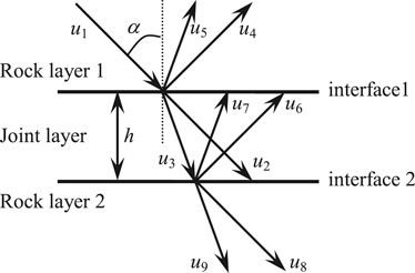
FIGURE 1. Schematic diagram of multiple transmissions and reflections of a stress wave through joints.
According to the superposition principle, the relationship between the waveforms in a single-jointed rock mass can be obtained: The outgoing P wave u4 in rock layer 1 is equal to the superposition of the reflected P wave component of incident P wave u1, the transmitted P wave component of outgoing P wave u6 in the joint layer, and the transmitted P wave component of outgoing SV wave u7 in the joint layer. The outgoing SV wave u5 in rock layer 1 is equal to the superposition of the reflected SV wave component of incident P wave u1, the transmitted SV wave component of outgoing P wave u6 in the joint layer, and the transmitted SV wave component of outgoing SV wave u7 in the joint layer. The inward P wave u8 in rock layer 2 is equal to the superposition of the transmitted P wave component of inward P wave u2 in the joint layer and the transmitted P wave component of inward SV wave u3. The inward SV wave u9 in rock layer 2 is equal to the superposition of the transmitted SV wave component of inward P wave u2 in the joint layer and the transmitted SV wave component of inward SV wave u3. The inward P wave u2 in the joint layer is equal to the superposition of the transmitted P wave component of incident P wave u1, the reflected P wave component of outgoing P wave u6 in the joint layer, and the reflected P wave component of outgoing SV wave u7 in the joint layer. The inward SV wave u3 in the joint layer is equal to the superposition of the transmitted SV wave component of incident P wave u1, the reflected SV wave component of outgoing P wave u6 in the joint layer, and the reflected SV wave component of outgoing SV wave u7 in the joint layer. The outgoing P wave u6 in the joint layer is equal to the superposition of the reflected P wave component of inward P wave u2 and the reflected P wave component of inward SV wave u3 in the joint layer. The outgoing SV wave u7 in the joint layer is equal to the superposition of the reflected SV wave component of inward P wave u2 and the reflected SV wave component of inward SV wave u3 in the joint layer.
Next, the stress wave systems on interfaces 1 and 2 are taken as research objects, and the coordinate systems are established (Figure 2). Assuming that waveforms on all sides are harmonic, the relationship between waveforms on interface 1 is shown in Eqs. 1–4:
where TPP1j represents the transmission coefficient of P wave transmitted from rock 1 through interface 1; TPS1j represents the transmission coefficient of SV wave transmitted by rock 1 through interface 1; RPP1j represents the reflection coefficient of P wave reflected by rock 1 through interface 1; RPS1j represents the reflection coefficient of SV wave reflected from rock 1 through interface 1.
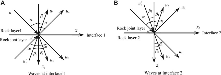
FIGURE 2. Incidental, reflective, and transmitted stress waves at interfaces.
TPPj1 represents the transmission coefficient of P wave transmitted by joint 1 through interface 1; TPSj1 represents the transmission coefficient of SV wave transmitted by joint 1 through interface 1; RPPj1 represents the reflection coefficient of P wave reflected by joint 1 through interface 1; RPSj1 represents the reflection coefficient of SV wave reflected by P wave passing through interface 1 from joint 1; TSPj1 represents the transmission coefficient of P wave transmitted by joint 1 through interface 1; TSSj1 represents the transmission coefficient of SV wave transmitted by joint 1 through interface 1; RSPj1 represents the reflection coefficient of P wave reflected by SV wave passing through interface 1 from joint 1; RSSj1 represents the reflection coefficient of SV wave reflected from joint 1 through interface 1.
The relationship between waveforms at interface 2 is shown in Eqs. 5–8:
where TPPj2 represents the transmission coefficient of P wave transmitted from joint 1 to interface 2; TPSj2 represents the transmission coefficient of SV wave transmitted by joint 1 through interface 2; RPPj2 represents the reflection coefficient of P wave reflected from joint 1 through interface 2; RPSj2 represents the reflection coefficient of SV wave reflected by P wave passing through interface 2 from joint 1; TSPj2 represents the transmission coefficient of P wave transmitted from joint 1 to interface 2; TSSj2 represents the transmission coefficient of SV wave transmitted by joint 1 through interface 2; RSPj2 represents the reflection coefficient of P wave reflected by SV wave passing through interface 2 from joint 1; RSSj2 represents the reflection coefficient of SV wave reflected from joint 1 through interface 2.
According to the propagation law of stress wave in elastic medium, the relationships between u2 and
where h is the thickness of the joint layer; cpj and csj are, respectively, the propagation velocities of the P wave and SV wave in the joint layer, α1 and β1 are, respectively, the angles between the P wave and SV wave in the joint layer and the interface normal.
According to the propagation law of stress wave in elastic medium, the relationships between u6 and u’ 6, u7, and u’ 7 are:
The general expression of each wave is as follows [27]:
where kxn is the number of SV waves. When the component of the stress wave in the X-direction is in the same direction as the X-axis, kxn = ωsinϕn/csn. When the component of the stress wave in the X-direction is opposite to the X-axis direction, kxn = -ωsinϕn/csn. In a similar way, kzn is the number of P waves. When the component of the stress wave in the Z-direction is in the same direction as the Z-axis, kzn = ωcosϕn/cpn. When the component of the stress wave in the Z-direction is opposite to the Z-axis direction, kzn = -ωcosϕn/cpn. ϕn is the angle between the stress wave and interface normal, csn is the velocity of the SV wave, and cpn is the velocity of the SV wave.
The relationship between the amplitudes of each wave can be obtained from Eqs. 1–13:
where m1 = exp [-iωh/(cpjcosα1)], m2 = exp [-iωh/(csjcosβ1)], Rpp = A4/A1, Rps = A5/A1, Rpp and Rps are, respectively, the total reflection coefficients of the P and SV waves of the P wave reflected from rock layer 1 through the joint layer and back to rock layer 1, and ω is the circular frequency of the incident wave. Mk = Ak/A1 (k = 2,3,6,7),Tpp = A8/A1, Tps = A9/A1, andTpp and Tps are, respectively, the total transmission coefficients of P and SV waves of the P wave transmitted from rock layer 1 through the joint layer and back to rock layer 2.
When the P wave is normally incident (α = 0°), the stress wave will not produce a converted wave, and then Eq. 14 can be simplified to:
From equations (15) and (17):
Substituting Eqs. 20 and (19) into Eqs. 16 and (18), respectively:
For the actual rock mass with multiple parallel joints, as shown in Figure 3A, the method of calculating the total transmission and reflection coefficients of a single-jointed rock mass when the P wave incident is vertical can still be generalized. First, the joint layers 1 to (m-1) are regarded as an interface x (Figure 3B). Then, the group parallel joint model can be equivalent to many single-joint models, so the recursive formula for the transmission and reflection coefficients with P wave vertical incidence can be deduced by Eqs. (21) and (22).
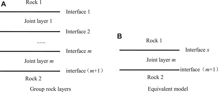
FIGURE 3. Schematic diagram of group parallel joint model.
In order to obtain the transmission and reflection coefficients of the joint layer m with P wave vertical incidence, it is necessary to know the transmission and reflection coefficients of the joint layer (m-1) with P wave vertical incidence. In order to obtain the transmission and reflection coefficients of the joint layer (m-1) with P wave vertical incidence, it is necessary to know the transmission and reflection coefficients of joint layer (m-2) with P wave vertical incidence. By analogy, in order to obtain the transmission and reflection coefficients of joint layer 2 with P wave vertical incidence, it is necessary to know the transmission and reflection coefficients of joint layer 1 with P wave vertical incidence. For the problem of P wave vertical incidence on the single-joint layer, the transmission and reflection coefficients of P wave vertical incidence on joint layer 1 can be obtained by using Eqs. (21) and (22). By analogy, the transmission and reflection coefficients of joint layer m can be calculated when P waves incidents are vertical.
Suppose that there is a joint layer with thickness h in a rock mass, the two sides of the joint layer are complete rocks, and the joint is seamlessly connected with the rock. In order to test the elastic modulus and Poisson's ratio of the joint, measuring points for recording the stress waveform are arranged on both sides of the joint. The arrangement of vibration source points, measuring lines, and measuring points are shown in Figure 4. In the field test, the incident wave is generated by a geological hammer striking at the source point, and two three-directional acceleration sensors with frequencies ranging from 0.2 Hz to 5 kHz are arranged at measuring points 1 and 2 to record the vibration waveforms.
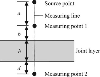
FIGURE 4. Schematic diagram of measuring points.
A vibration load with small stress amplitude is generated at the source point, and both the rock layer and the joint layer are elastically deformed. According to the spherical diffusion effect of the stress wave excited by the point source in the rock mass and the spectrum of the transmitted wave at measuring point 2, the calculated spectrum of the incident and the reflected wave can be, respectively, obtained.
In the formula:
where u2(ω) is the measured P wave spectrum at point 2, Tpp and Rpp are, respectively, transmission and reflection coefficients of the joint layer with P wave vertical incidence. k1 and k2 are the amplitude attenuation parameter caused by spherical diffusion of the point source and the waveform phase variation parameter caused by propagation distance, respectively, i is an imaginary number unit; DI, DR, and DT are the spherical diffusion compensation coefficients of incident, reflected, and transmitted waves, respectively [27]:
If the incident wave is a plane wave, the spherical compensation coefficient of each wave is 1, that is, DI = DR = DT = 1; cP1, cPj, and cP2 are the propagation velocities of P wave in rock, joint, and rock in point 2, respectively; TPP and RPP are calculated by equations [21, 22].
Since the measured waveform of measuring point 1 is a coherent waveform of the incident wave propagating to measuring point 1 and the reflected wave propagating to measuring point 1, the calculated spectrum of the measured waveform at measuring point 1 can be obtained by using the measured waveform spectrum at measuring point 2:
Inverse Fourier transformation on both sides of Eq. 25 can be used to calculate the waveform u1js at measurement point 1. If the deformation characteristics of the joint conform to the single-joint model assumption, u1js is the same as the measured waveform u1. Due to the error of the model hypothesis and the interference factors in the field test, there is a deviation between u1js and u1. Using the principle of the least square method, taking P wave velocity cpj as an unknown variable and fitting u1js to the measured waveform u1 at point 1 (Eq. 26), finally, when the weighted average error is the smallest, the corresponding cpj is the calculated P wave velocity cpjjs in the joint.
When the incident wave is the SV wave, the transmission and reflection coefficients are calculated by replacing the P wave velocity with the SV wave velocity of the rock on both joint sides, and the calculated SV wave velocity csjjs can also be obtained by the least square method:
where ρj is the joint density.
We selected a typical macro-joint with a length of 5.60 m and a thickness of 0.04 m on a flat slope next to Luojiang Luquan Water Plant in Gangzhou China for the elastic parameter test [11, 12]. The measuring point and the vibration source are arranged as shown in Figure 5. Two three-directional acceleration sensors were closely attached to measuring points 1 and 2 using gypsum. The distance between the two measuring points and the joint was 0.10 m, and the distance between the source point and the joint was 0.60 m. The P-waveform is recorded in the x-direction of the sensor to test the P wave velocity of the joint, and the SV-waveform is recorded in the y-direction of the sensor to test the SV wave velocity of the joint.
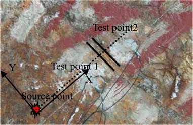
FIGURE 5. The vibration source and measuring point locations of the field test.
In the method to test joint elastic parameters described above, it is necessary to know the P and SV wave velocities at measuring points 1 and 2, the rock density, and the joint density. We tested the velocities of the P and SV waves using the wave velocity method. First, a line parallel to the joint is arranged on the side of measuring point 1. Two measuring points are selected at a distance of 1.50 m from the measuring line. Then, a source point is selected on the extension line of the two measuring points, and a geological hammer is used to knock the source point five times. Finally, according to the time difference between the measured waveforms of the two measuring points and the distance between the two measuring points, the P and SV wave velocities at point 1 of the rock mass can be calculated (Table 1). Similarly, the P and SV wave velocities at point 2 can be measured. The joint and the rocks on both sides were sampled and physically processed into standard samples, and then, the mass and volume of the samples were measured to obtain a joint density of 2357 kg/m3 and a rock density of 2645 kg/m3.

TABLE 1. P-SV wave velocity of the rock mass at point 1 (wave velocity method).
The vibration source point shown in Figure 5 is knocked, the P-SV waveforms of measurement points 1 and 2 are recorded as shown in Figure 6, and the P-SV waveforms of points 1 and 2 are recorded as up1, up2, us1, and us2, respectively. The Fourier transform of up2 and us2, respectively, can obtain frequency spectrums ũp2 and ũs2 of the measured waveform at point 2, and Eqs. 23–26 can be used to calculate the velocities of the P and SV waves in the joint. Six tests were carried out on the site joints, and the wave velocities of P and SV were calculated by the above waveform method (Table 2). Finally, by substituting the average calculated wave velocity into Eqs. 25 and (26), the joint elastic modulus and Poisson's ratio are 6.03 GPa and 0.19, respectively.
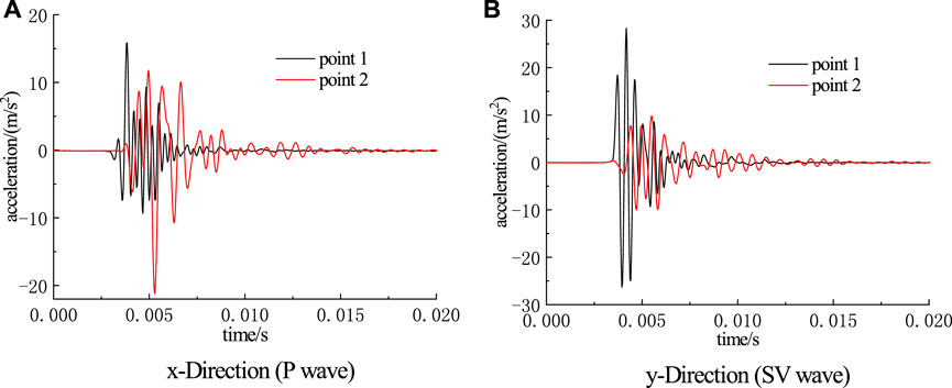
FIGURE 6. Measured waveform of points 1 and 2.
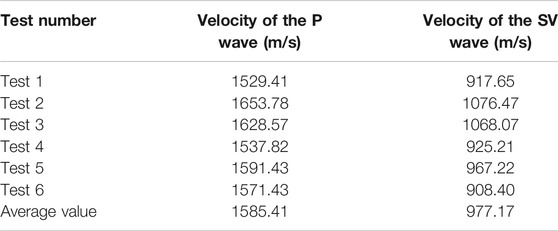
TABLE 2. P-SV wave velocity of the joint layer (waveform method).
According to the law of transmission and reflection of a stress wave through a single joint, the waves in the same direction and the same type are superposed in this article, and the analysis model of stress waves passing through single-joint rock is established. On this basis, the macro-joint model of stress waves passing through a group of parallel jointed rocks is proposed. Taking a vertical stress wave incident into a single macroscopic jointed rock stratum as an example, the calculation waveform of the incident wave is calculated according to the measured wave form of the transmission wave by using the above analysis model. The calculated wave form of the incident wave is compared with the measured wave form, and the node elastic parameter with the minimum error can be obtained by using the principle of the least square method. The results of six tests on joints with a thickness of 0.04 m show that the proposed method has good stability.
In this article, in order to simplify the analysis steps, it is assumed that the joint surface is straight and smooth, and the stress wave incident is vertical. In order to improve the applicability of the joint elastic parameter test method, more general joint model analyses and research will be developed in the future.
The original contributions presented in the study are included in the article/Supplementary Material; further inquiries can be directed to the corresponding author.
JD put forward the research ideas and designed the research scheme. YF and GW were responsible for the experiment. JD and YF were responsible for collecting, cleaning, and analyzing the data; JD, YF, and GW are responsible for drafting the paper. GW is responsible for the revision to the final version. In the end, all authors agreed to publish.
Financial support of the work by the National Natural Science Foundation of China (51464015, 41462009, and 51104069) and the Research Fund of Jiangxi University of Science and Technology (NSFJ2014-G06) is gratefully acknowledged.
JD was employed by the Fujian Makeng Mining Co., Ltd.
The remaining authors declare that the research was conducted in the absence of any commercial or financial relationships that could be construed as a potential conflict of interest.
1. Zhang Q. The transfer process of stress waves at the joint. Chin J Geotech Eng (1986) 8(6):99–105. [in Chinese, with English summary].
2. Li XB, Chen SR. A new method for investigating the propagation of stress waves through layered rock mass. J Cent South Univ (Sci Technol) (1993) 24(6):738–42. [in Chinese, with English summary].
3. Pyrak-Nolte LJ, Myer LR, Cook NGW. Anisotropy in seismic velocities and amplitudes from multiple parallel fractures. J Geophys Res (1990) 95(B7):11345–58. doi:10.1029/jb095ib07p11345
4. Pyrak-Nolte LJ, Myer LR, Cook NGW. Transmission of seismic waves across single natural fractures. J Geophys Res (1990) 95(B6):8617–38. doi:10.1029/jb095ib06p08617
5. Cai JG, Zhao J. Effects of multiple parallel fractures on apparent attenuation of stress waves in rock masses. Int J Rock Mech Mining Sci (2000) 37(4):661–82. doi:10.1016/s1365-1609(00)00013-7
6. Cai JG. Effects of parallel fractures on wave attenuation in rock. Singapore: Nanyang Technological University (2001).
7. Li JC, Li HB, Ma GW, Zhao J. A time-domain recursive method to analyse transient wave propagation across rock joints. Geophys J Int (2012) 188(2):631–44. doi:10.1111/j.1365-246x.2011.05286.x
8. Li JC, Ma GW, Zhao J. An equivalent viscoelastic model for rock mass withparallel joints. J Geophys Res (2010) 115(B03305):1–10. doi:10.1029/2008jb006241
9. Wang GS, Guo Y, Hu SL. Measuring method for viscosity coefficient of rock. Prog Geophys (2014) 29(5):2411–5. [in Chinese, with English summary].
10. Wang G, Wang X, Hu S. A dynamic measurement method of elastic modulus of weak interlayer of rock mass. Chin J Rock Mech Eng (2015) 34(9):1828–35. [in Chinese, with English summary]. doi:10.13722/j.cnki.jrme.2014.0873
11. Hu SL. Propagation rule and application of wavelet across the jointed rock mass. Peiking: China University of Geosciences (2014) [in Chinese, with English summary].
12. Long P, Wang G, Hu S, Luo S. Measuring stiffness of jointed rock based on spectrum variation of stress wave. Chin J Rock Mech Eng (2015) 34(8):1677–83. [in Chinese, with English summary]. doi:10.13722/j.cnki.jrme.2015.0120
13. Gou Y, Shi X, Qiu X, Zhou J. Propagation characteristics of blast-induced vibration in parallel jointed rock mass. Int J Geomechanics (2019) 19(5):1–14. doi:10.1061/(asce)gm.1943-5622.0001393
14. Behnia M, Goshtasbi K, Marji MF, Golshani A Numerical simulation of crack propagation in layered formations. Arab J Geosci (2014) 7(7):2729–37. doi:10.1007/s12517-013-0885-6
15. Marji MF. Numerical analysis of quasi-static crack branching in brittle solids by a modified displacement discontinuity method. Int J Sol Structures (2014) 51(9):1716–36. doi:10.1016/j.ijsolstr.2014.01.022
16. Chen E, Leung CKY, Tang S, Lu C. Displacement discontinuity method for cohesive crack propagation. Eng Fracture Mech (2018) 190:319–30. doi:10.1016/j.engfracmech.2017.11.009
17. Wang GS, Xiong P, Hu SL, Meng SM. Application of displacement discontinuity model for calculating the viscoelastic stiffness of joints. Rock Soil Mech (2018) 39(6):2175–83. [in Chinese, with English summary]. doi:10.16285/j.rsm.2016.2047
18. Wang GS, Liu SQ, Hu SL. Improved linear elastic model of discontinuous displacement and dynamic measurement of interface elastic modulus. Chin J Rock Mech Eng (2016) 35(10):2022–32. [in Chinese, with English summary].
19. Wang ZL, Chen Q, Zhang Y. A displacement discontinuity model for viscoelastic jointed rock mass. Rock Soil Mech (2015) 36(8):2177–83. [in Chinese, with English summary]. doi:10.16285/j.rsm.2015.08.007
20. Zhu JB, Zhao J. Obliquely incident wave propagation across rock joints with virtual wave source method. J Appl Geophys (2013) 88:23–30. doi:10.1016/j.jappgeo.2012.10.002
21. Gordeliy E, Detournay E. Displacement discontinuity method for modeling axisymmetric cracks in an elastic half-space. Int J Sol Structures (2011) 48(19):2614–29. doi:10.1016/j.ijsolstr.2011.05.009
22. Li J, Ma G. Analysis of blast wave interaction with a rock joint. Rock Mech Rock Eng (2010) 43(6):777–87. doi:10.1007/s00603-009-0062-0
23. Schoenberg M. Elastic wave behavior across linear slip interfaces. The J Acoust Soc Am (1980) 68(5):1516–21. doi:10.1121/1.385077
24. Schoenberg M, Douma J. Elastic wave propagation in media with parallel fractures and aligned Cracks1. Geophys Prospect (1988) 36(6):571–90. doi:10.1111/j.1365-2478.1988.tb02181.x
26. Ge G. The basis of seismic wave dynamics[M]. Peiking: Petroleum Industry Press (1980) [in Chinese, with English summary].
27. Wang LL. Stress wave foundation. Beijing: National Defense Industry Press (1985). p. 248. [in Chinese, with English summary].
Keywords: stress wave, macro-joint, rock stratum model, vertical incidence, dynamic test
Citation: Dong J, Fu Y and Wang G (2021) An Analytical Method to Test Elastic Rock Mass Parameters Based on a Macro-Joint Model. Front. Phys. 9:587477. doi: 10.3389/fphy.2021.587477
Received: 26 July 2020; Accepted: 22 January 2021;
Published: 11 March 2021.
Edited by:
Guoyang Fu, Monash University, AustraliaReviewed by:
Wenzheng Yue, China University of Petroleum, ChinaCopyright © 2021 Dong, Fu and Wang. This is an open-access article distributed under the terms of the Creative Commons Attribution License (CC BY). The use, distribution or reproduction in other forums is permitted, provided the original author(s) and the copyright owner(s) are credited and that the original publication in this journal is cited, in accordance with accepted academic practice. No use, distribution or reproduction is permitted which does not comply with these terms.
*Correspondence: Yuhua Fu, ZnloMTM2OUAxMjYuY29t
Disclaimer: All claims expressed in this article are solely those of the authors and do not necessarily represent those of their affiliated organizations, or those of the publisher, the editors and the reviewers. Any product that may be evaluated in this article or claim that may be made by its manufacturer is not guaranteed or endorsed by the publisher.
Research integrity at Frontiers
Learn more about the work of our research integrity team to safeguard the quality of each article we publish.