 Xinghua Li
 Mingde Feng*
 Jiafu Wang
 Jiaheng Yang
 Ruichao Zhu
94% of researchers rate our articles as excellent or good
Learn more about the work of our research integrity team to safeguard the quality of each article we publish.
Find out more
ORIGINAL RESEARCH article
Front. Phys. , 25 September 2020
Sec. Optics and Photonics
Volume 8 - 2020 | https://doi.org/10.3389/fphy.2020.578295
This article is part of the Research Topic Advanced Photonics Metasurfaces: Design, Fabrication, and Applications View all 15 articles
Edge scattering is one of the main scattering sources for metal objects, especially for those with thin front edges. In this paper, based on the principle of scattering cancelation, a coding metasurface purfle is proposed and employed to suppress the edge back-scattering of electromagnetic (EM) waves. To this end, two split-ring resonators with a π phase difference between them are designed to act as the 0- and 1-element of the coding metasurface. The coding metasurface fixed on the front edge of a thin metal plate can reduce the edge back-scattering significant for EM waves polarized along the edge direction due to the anti-phase scattering of the two coding elements. Both the simulation and experiment results verify the reduced back-scattering of the flat edge. A maximal reduction of 24 dB is attained within the central frequency of about 11 GHz. This work provides a novel alternative to suppressing edge scattering and may find applications in EM compatibility, radar stealth technologies, etc.
Edge scattering, as a strong scattering phenomenon, can be interpreted as scattering from discontinuous impedance between the edges of the considered targets and their surroundings [1]. Edge scattering can be excited by plane waves impinging upon the surface of a metal object. In fact, when a metal object is illuminated by an oblique incidence, specular reflection also arises, as shown in Figure 1A. But considering the distance between the source and an object, plane waves often form in a grazing condition when they arrive at a detected object [2]. In this scenario, edge scattering is the main contributor to radar cross-section (RCS) at a large angle incidence. For low RCS applications, such as stealth techniques, antennae, and RCS measurement ranges, it is crucial to suppress edge scattering in order to improve the performance of the research targets [3].
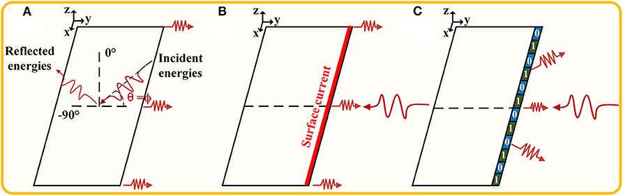
Figure 1. Suppression of edge scattering. The plane waves illuminate a rectangular metal surface. (A) Scattering pattern at an oblique incident angle of θ = ϕ (0° < ϕ <90°). (B) Edge back-scattering under horizontal polarization at the incident angle of θ = 90°. (C) The schematic of coding metasurface purfle used to suppress edge back-scattering.
Edge scattering can be suppressed by the design of the geometry and material property [4]. From the perspective of geometric design, Ufimtsev proposed a principle of using geometrical shape to minimize the back-scattering [5]. Afterwards, there have been several different geometrical shapes that were implemented [6–12]. From the perspective of material property design, the methods for edge scattering suppression include the use of edge corrugations, resistive taper loading, and edge coatings, etc., which have received considerable attention [13–24]. In addition, other related works include using inhomogeneous anisotropic impedance surfaces to guide surface waves with the purpose of suppressing the scattering of the hypotenuse of triangular scatterer [25] and using hard and soft anisotropic impedance surfaces to redirect the back-scattering [26]. However, many of the methods just mentioned suffer from obvious limitations when considering other engineering indicators, such as weight or aerodynamic performance [26]. So, in this paper, a coding metasurface purfle is proposed to suppress edge scattering following the principle of scattering cancelation. Compared with previously published references, this approach provides an alternative tool for suppression of edge scattering, without changing physical geometry, exhibiting excellent properties, including ease of fabrication, lightness of weight, and thinness of thickness. Coding metasurfaces have digital coding sequences, which can regulate EM waves by various combinations of different coding sequences. They are part of a class of structures, generally called metasurfaces, which include high impedance surface (HIS), electromagnetic bandgap (EBG), artificial impedance surface (AIS), and so forth. These metasurfaces are relevant to multiple applications for antennas, lenses, absorbers, imaging, and waveguides [27–34]. But, until now, using coding metasurfaces to reduce edge scattering has rarely been reported.
The basic principle of this paper is illustrated in Figure 1: When horizontal polarized plane waves illuminate a metal plate, the current can be induced on the front edge, due to the edge effect shown in Figure 1B [35], which generates the strong back-scattering. Therefore, we would expect to change the distribution of edge current in order to reduce the back-scattered energy according to the scattering cancelation principle. Following this idea, two coding elements with π phase difference are designed to realize the energy cancelation along the back-scattering direction. Then, the elements constitute the coding metasurface purfle, which are fixed on the front edge of a metal plate, as shown in Figure 1C. It is worth noting that two coding elements are arranged in a coding scheme similar to the grating structure. In addition, for the sake of simplicity of analysis, the incident angle of the plane wave is taken as 90°. A series of procedures of simulations and experiments have been carried out to verify the back-scattering suppression performance of our proposal. As we expected, both results indicate that this method is highly effective at the issues of suppressing edge scattering.
There are two polarizing cases when the plane waves illuminate a rectangular metal plate at an incident angle of 90° as shown in Figure 2A. One is the excited electric field E1, which is parallel to the incident plane (x–y plane), and the other, E2, is perpendicular to the incident plane. These two exciting conditions are defined as horizontal and vertical polarization, respectively. As described commonly, the scattering of a thin metal plate under horizontal polarization is stronger than that which is under the vertical one at an incident angle of 90° due to electrons by horizontal polarization driving, which can generate the front edge current to scatter energy [5]. Theoretical research indicates that the edge scattering under horizontal polarization is independent of frequency and only varies with the square of the edge length. The mono-static RCS of edge scattering can be calculated by [6]
where σ is RCS of edge backward scattering and l is the length of front edge.
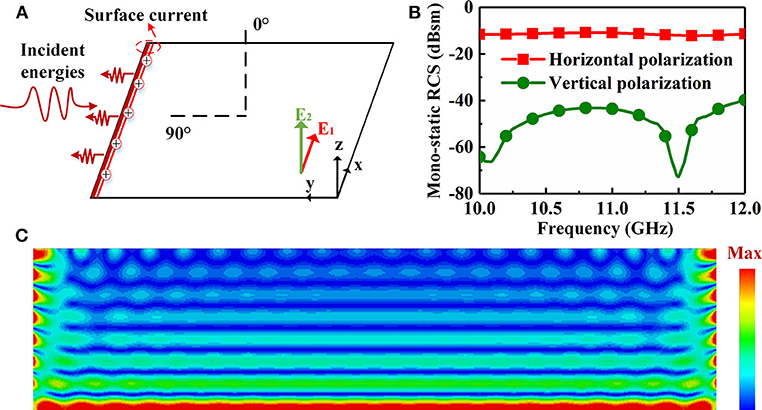
Figure 2. Illustrations of edge scattering of a thin rectangular metal plate. (A) Edge scattering at an incident angle of 90°. (B) The mono-static RCS of edge scattering under horizontal and vertical polarization. (C) Surface current on metal plate under a horizontal polarized incidence.
To further validate the analysis for the edge scattering of a metal plate, the CST 2018 simulation tool is used to calculate mono-static RCS of the metal plate under two different polarizations. In this case, the dimension of rectangular metal plate is 480 × 90 mm, and its thickness is 0.017 mm. As is shown in Figure 2B, the mono-static RCS of the metal plate under two polarizations are simulated at a frequency ranging from 10 to 12 GHz. It is obvious that the RCS under horizontal polarization (average value is −11 dB) is higher than that under vertical polarization (average value is −50 dB), which is in line with the conclusion mentioned above. So, in this investigation, edge scattering under horizontal polarization is the main focus of our study. According to Equation (1), the mono-static RCS under horizontal polarization can be calculated, with the result being about −11.3 dB, which also agrees with the simulated result. To intuitively understand the mechanism of edge scattering under horizontal polarized incidence, the distribution of surface current is simulated as shown in Figure 2C. Note that the current on the front edge is more intense than that on the other areas, which further verifies that the front edge of a metal plate is the major scattering source.
As described above, the front-edge current scatters energy in a backward direction. In order to suppress the edge back-scattering, coding elements should be designed to change the distribution of edge current. Based on this, two coding elements numbered 0-element and 1-element have been used to divide the edge current into two different parts, following the principle of scatter cancelation. When the plane waves illuminate a metal plate, two coding elements fixed on the front edge can be considered as two different scattering sources. The wave functions of the EM waves scattered by the two sources can be written as:
Where ω is the angular frequency of EM waves, A0 and A1 are amplitudes, and φ0 and φ1 are initial phases. Assume that there is a point p in the normal direction of the front edge. The distance between the sources and the point is r0 and r1, respectively. When the EM wave y0 and y1 meet at this point, the superposition function at this point can be described as:
where φ and A are the superimposed initial phase and amplitude, respectively. The superimposed amplitude meets the following expressions:
where λ is the wavelength of free space. Based on Equations (5) and (6), the maximum reduction of scattering at the point p can be obtained under the conditions of A0 = A1 and Δ φ = (2k + 1) π, (k = 0,1,2…). Similarly, if we want to suppress the edge back-scattering in the normal direction of the front edge, the foundation of the whole design process is also to find the two conditions just mentioned. Considering that the magnetic field of horizontal polarization is perpendicular to the front edge, a simple split-ring resonator with magnetic resonance can be employed to regulate the phase and amplitude.
The coding elements, illustrated in Figure 3A, consist of the split rings etched on a 3-mm thick commercial dielectric FR4 (εr = 4.3, tan δ = 0.025) with a copper ground plane on the bottom side. The split ring and copper ground plane have identical thickness of 0.017 mm. The configuration parameters after the parameter sweep by virtue of the CST are designed as follows: The period of element is p = 5 mm, and the length is w = 90 mm; the radius of split ring r = 2 mm, and the width is wr = 0.1 mm; and the size of split is g = 0.2 mm. In the next step, the Frequency Domain solver function in CST 2018 is used to numerically calculate the amplitudes and phases of two coding elements. Unit cell boundaries are applied to the x axis and y axis directions, and the z planes are set as open boundaries. The height of the upper boundary to the coding element is 25 mm. The plane waves illuminate the elements along z axis. It should be emphasized that the electric field of the incident waves is always parallel to coding elements. The simulated results are shown in Figures 3B,C. In Figure 3C, the condition of π phase difference is obtained at 11.16 GHz. Meanwhile, the values of amplitudes of two coding elements are small and approximately equal, which also satisfies the other condition of A0 = A1. Therefore, we can preliminarily speculate that the edge back-scattering can be suppressed at about 11.16 GHz. In order to further interpret the generation mechanism of the π phase difference, surface current and magnetic field of coding elements at 11.16 GHz are simulated and shown in Figure 4A. It can be seen that the surface current forms a closed loop, and a strong magnetic field is generated due to the resonance. Note that the intensity of resonance of two coding elements is different and that the intensity of 1-element is stronger than that of 0-element. Thus, the conclusion can be drawn that the π phase difference is produced by the magnetic resonance. In addition, the absorption of two coding elements is also investigated as shown in Figure 4B. There is little difference of absorption between the coding elements and copper plate at the operating frequency of 11.16 GHz, which implies that the coding elements cannot absorb EM waves.
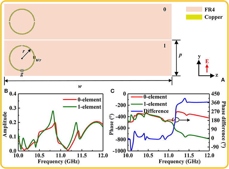
Figure 3. The coding elements used to regulate the amplitude and phase. (A) Top view of the coding elements numbered 0-element and 1-element. (B) The amplitudes of reflection coefficient of two coding elements. (C) The phases and phase difference of two elements.
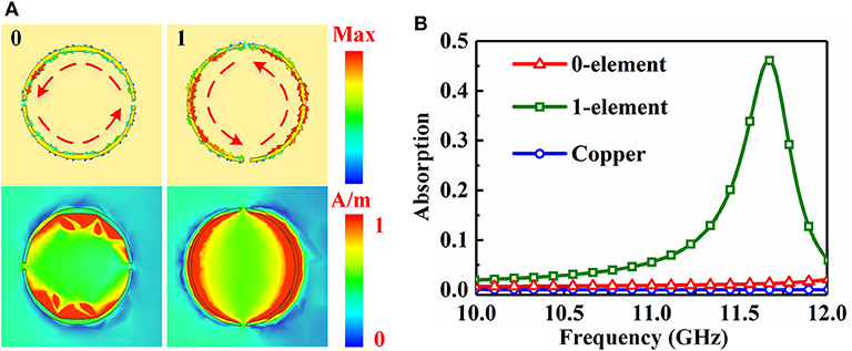
Figure 4. (A) The surface current and magnetic field of two coding elements at 11.16 GHz. (B) The absorption of two coding elements.
In order to verify the performance of coding elements for suppressing the edge back-scattering, two coding elements are fixed on the front edge of a rectangular copper plate to constitute a coding metasurface purfle. The spatial positions of regions 0-element and 1-elememt alternate periodically with a spatial period length of 6p, which is similar to the grating structure. The period length approximately corresponds to the wavelength of the operating frequency. The complete configuration is illustrated in Figure 5A. The simulated mono-static RCS of the patterned plate with coding metasurface purfle is shown in Figure 5B. In this simulation, the boundaries are all set as open (add space). When the plane waves illuminate the patterned plate along x axis, it can be seen that the result of patterned plate demonstrates a low RCS feature, compared with the copper plate. The proposal achieves desirable reduction band over 10 dB, from 10.82 to 11.3 GHz, and the peak reduction at around 11 GHz is consistent with our reasonable analysis. Figure 5D illustrates the RCS plane of the two plates. The copper plate has a single main backward lobe marked by the red arrow; but, the backward lobe of coding metasurface purfle splits into two parts due to the scattering cancelation, which also implies that coding metasurface purfle can suppress the edge back-scattering under horizontal polarization. It should be noted that the coding metasurface purfle is very good for horizontal polarization, but not as efficient for vertical polarization. This is because the magnetic field of vertical polarization is parallel to the coding elements, which cannot excite magnetic resonance on the split rings. What's more, with regard to propagation of surface wave, the FR4 substrate contributes much more, compared to the metal plate, and hence can make a stronger scatter in the backward direction. The mono-static RCS curves of copper plate, FR4 substrate with copper ground plane, and the patterned plate with coding metasurface purfle are shown in Figure 5C. The RCS value of FR4 substrate with copper ground plane has a slight difference compared with that of the patterned plate, and both the RCS values are higher than that of copper plate at the operating frequency, which demonstrates that the coding metasurface purfle is actually not efficient for vertical polarization and hence is consistent with the analysis mentioned above.
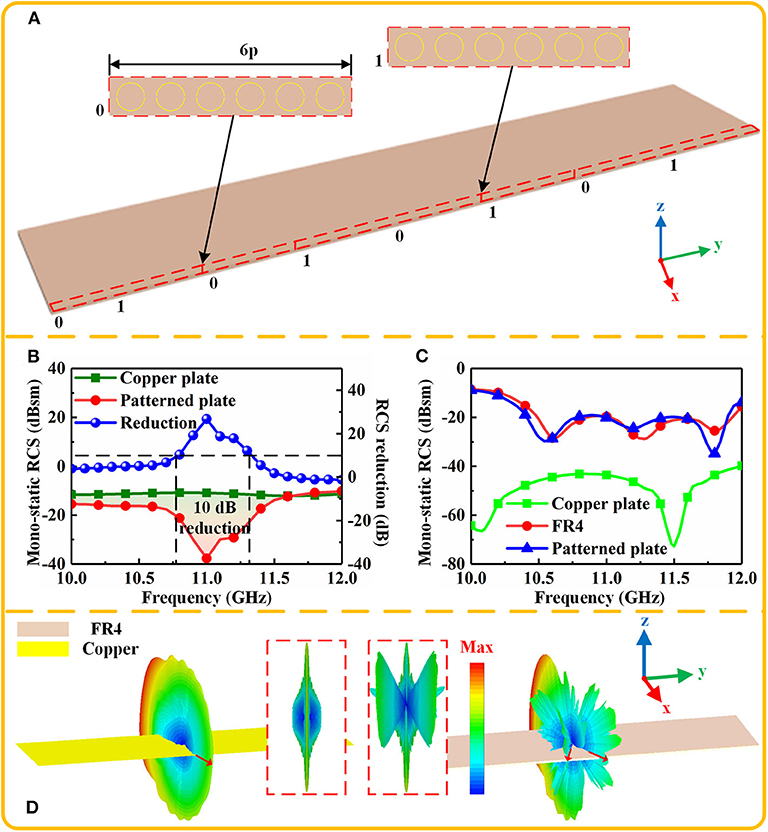
Figure 5. (A) The configuration of patterned plate with coding metasurface purfle constituted by anti-phase coding elements. (B) The mono-static RCS of copper plate and patterned plate under horizontal polarization. (C) The mono-static RCS of copper plate, FR4 substrate with copper ground plane and patterned plate under vertical polarization. (D) The RCS plane of copper plate and patterned plate under horizontal polarization at 11 GHz.
The simulated results provide a primary verification for the coding metasurface purfle to suppress the edge back-scattering issue; now, we turn to the measurement demonstration. The patterned plate with coding metasurface purfle was fabricated using Print Circuit Board (PCB) technique, and the dimensions of fabricated sample are the same as those in the simulation. The measurement was performed in a microwave anechoic chamber, and the measurement picture is shown in Figure 6A. The RCS reduction for the sample is the reflection in the far field condition [36]. Here, the reflection has been performed in a low cost and simple way to represent the RCS reduction, and the measured curves of RCS reduction are presented in Figure 6B. The patterned plate has a reduction of 10 dB from 10.7 to 11.05 GHz with a reduction peak of 21 dB at 10.7 GHz. The measured and simulated results have good agreements with slight difference, which may be brought by the imperfection in the fabricating process. Hence, it can be concluded that the coding metasurface purfle is actually effective on suppressing the edge back-scattering.
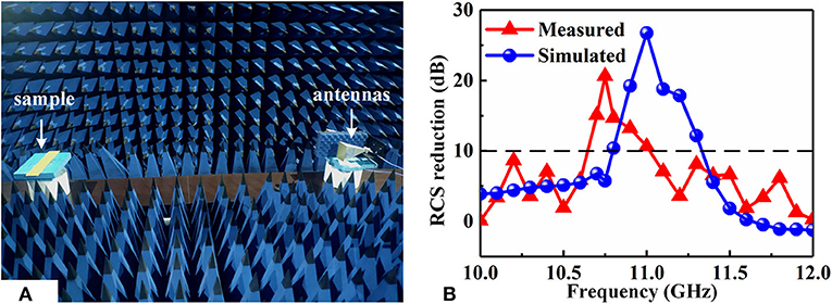
Figure 6. (A) The measurement setup for RCS reduction measurement. (B) Comparison of simulated and measured RCS reduction.
A coding metasurface purfle is proposed in order to suppress the edge back-scattering by using the principle of scattering cancelation. Two split rings with π phase difference constitute the coding elements to implement the scattering cancelation principle. The scattering of a rectangular copper plate and the patterned plate with coding metasurface purfle were then analyzed using numerical simulations. Finally, the experimental examination has been presented to verify the suppression performance of the patterned plate with coding metasurface purfle. The measured result is line with the simulated one, which demonstrates the feasible of our proposal. In addition, the method may gear toward various applications, such as improving stealth performance, reducing coupling between the antennas, eliminating unwanted lobes and EM compatibility. Furthermore, this work is only focused on reducing horizontal polarized scattering, and the incident angle is also limited. So, in the next step, we can keep on designing a structure that is independent on the polarization and incident angle.
All datasets generated for this study are included in the article/supplementary material.
XL: software, investigation, writing - original draft. MF: project administration. JW: conceptualization, methodology. YM: formal analysis, resources. JY: data curation. TL: modification. RZ: assistance in doing experiments. SQ: supervision, funding acquisition. All authors contributed to the article and approved the submitted version.
The authors are grateful for the support from the National Natural Science Foundation of China under Grant Nos. 61671466, 61971435, and 61901508.
The authors declare that the research was conducted in the absence of any commercial or financial relationships that could be construed as a potential conflict of interest.
1. Chen HY, Deng LJ, Zhou PH, Xie JL. Tapered impedance loading for suppression of edge scattering. IET Microwaves Antennas Propag. (2011) 5:1744–9. doi: 10.1049/iet-map.2010.0623
2. Zhou Y, Cao X, Gao J, Li S, Liu X. RCS reduction for grazing incidence based on coding metasurface. Electron Lett. (2017) 53:1381–3. doi: 10.1049/el.2017.2414
3. Chen HY, Zhu ZW, Lu LJ, Guan Y, Xie JL, Deng LJ. Design and implementation of the tapered resistive sheets to control edge scattering. J Appl Phys. (2014) 115:164906. doi: 10.1063/1.4874162
4. Kappa J, Dang Z, Sokoluk D, Rahm M. Analysis of coding metasurfaces for incident radiation at oblique incidence angles. OSA Continuum. (2019) 2:2172–80. doi: 10.1364/OSAC.2.002172
5. Ufimtsev PY. Method of Edge Waves in the Physical Theory of Diffraction. Foreign Technology Div Wright-Pattersonafb Oh. National Technical Information Service (1971).
6. Jenn D. Radar and Laser Cross Section Engineering. American Institute of Aeronautics and Astronautics, Inc. (2005).
7. Liu ZH, Huang PL, Wu Z, Gao X. Analysis of scattering from serrated edge plate on aircraft with MLFMA. J Beij Univ Aeronaut Astronaut. (2008) 34:499−502. doi: 10.3969/j.issn.1003-5060.2008.12.032
8. Liu D, Huang J, Song L, Ji J. Influence of aircraft surface distribution on electromagnetic scattering characteristics. Chin J Aeronaut. (2017) 30:759–65. doi: 10.1016/j.cja.2017.02.015
9. Kumar N, Vadera SR. Stealth Materials and Technology for Airborne Systems. Aerospace Materials and Material Technologies. Singapore: Springer (2017). p. 519–37. doi: 10.1007/978-981-10-2134-3_24
10. Ni X, Wong ZJ, Mrejen M, Wang Y, Zhang X. An ultrathin invisibility skin cloak for visible light. Science. (2015) 349:1310–4. doi: 10.1126/science.aac9411
11. Pu M, Li X, Ma X, Wang Y, Zhao Z, Wang C, et al. Catenary optics for achromatic generation of perfect optical angular momentum. Sci Adv. (2015) 1:e1500396. doi: 10.1126/sciadv.1500396
12. Xie X, Li X, Pu M, Ma X, Liu K, Guo Y, et al. Plasmonic metasurfaces for simultaneous thermal infrared invisibility and holographic illusion. Adv Funct Mater. (2018) 8:1706673. doi: 10.1002/adfm.201706673
13. Lee WS, Lee SJ, Lee DJ, Lee WS, Yu JW. TE scattering from concaved wedges with longitudinal corrugations. IEEE Transact Antennas Propag. (2012) 61:2355–9. doi: 10.1109/TAP.2012.2233703
14. Knott EF. Suppression of edge scattering with impedance strings. IEEE Transact Antennas Propag. (1997) 45:1768–73. doi: 10.1109/8.650194
15. Smith FC. Edge coatings that reduce monostatic RCS. IEE Proc Radar Sonar Navig. (2002) 149:310–4. doi: 10.1049/ip-rsn:20020717
16. Choi WH, Shin JH, Song TH, Kim JB, Lee WJ, Joo YS, et al. Design of thin circuit-analogue multilayer absorber and application to leading edge of wing structure. Electron Lett. (2013) 49:216–7. doi: 10.1049/el.2012.3983
17. Gustafsson M. RCS reduction of integrated antenna arrays with resistive sheets. J Electromagn Waves Appl. (2006) 20:27–40. doi: 10.1163/156939306775777323
18. Sjoberg D, Gustafsson M. Realization of a matching region between a radome and a ground plane. Progr Electromagn Res. (2010) 17:1–10. doi: 10.2528/PIERL10071906
19. Nam Y, Choi J, Jang M, Lee WJ, Kim CG. Radar-absorbing structure with nickel-coated glass fabric and its application to a wing airfoil model. Comp Struct. (2017) 180:507–12. doi: 10.1016/j.compstruct.2017.08.017
20. Choi W, Kwak B, Nam Y. Radar absorbing serrated edge for broadband radar cross-section reduction. Microw Opt Technol Lett. (2020) 62:1112–6. doi: 10.1002/mop.32152
21. Huang D, Lyo SK. Suppression of impurity and interface-roughness back-scattering in double quantum wires: theory beyond the Born approximation. J Phys Condens Matter. (2000) 12:3383. doi: 10.1088/0953-8984/12/14/314
22. Wang H, Liu W, Pan Z, Tao Y, Niu J, Tang J, et al. Suppression of backscattering-induced noise in a resonator optic gyro by the dual-frequency modulation method. Opt Commun. (2019) 459:124766. doi: 10.1016/j.optcom.2019.124766
23. Charola S, Patel SK, Parmar J, Ladumor M, Dhasarathan V. Broadband graphene-based metasurface solar absorber. Microw Opt Technol Lett. (2019) 62:1366–73. doi: 10.1002/mop.32156
24. Parmar J, Patel SK, Kartodiya D, Nguyen TK, Skibina JS, Dhasarathan V. Numerical investigation of gold metasurface based broadband near-infrared and near-visible solar absorber. Phys B Condens Matter. (2020) 591:412248. doi: 10.1016/j.physb.2020.412248
25. Hou H, Long J, Wang J, Sievenpiper DF. Reduced electromagnetic edge scattering using inhomogeneous anisotropic impedance surfaces. IEEE Transact Antennas Propag. (2017) 65:1193–201. doi: 10.1109/TAP.2016.2647681
26. Quarfoth R, Sievenpiper D. Alteration of electromagnetic scattering using hard and soft anisotropic impedance surfaces. IEEE Transact Antennas Propag. (2015) 63:4593–9. doi: 10.1109/TAP.2015.2458330
27. Liu Y, Li K, Jia Y, Hao Y, Gong S, Guo YJ. Wideband RCS reduction of a slot array antenna using polarization conversion metasurfaces. IEEE Transact Antennas Propag. (2016) 64:326–31. doi: 10.1109/TAP.2015.2497352
28. Lee GY, Hong JY, Hwang S, Moon S, Kang H, Jeon S, et al. Metasurface eyepiece for augmented reality. Nat Commun. (2018) 9:4562. doi: 10.1038/s41467-018-07011-5
29. Liu T, Meng Y, Ma H, Wang J, Zhu R, Chen H, et al. Extraordinary spoof surface plasmon polaritons excitation by linear and circular polarization conversions phase gradient metasurface. J Phys D Appl Phys. (2020) 53:045003. doi: 10.1088/1361-6463/ab522e
30. Sui S, Ma H, Wang J, Pang Y, Feng M, Xu Z, et al. Absorptive coding metasurface for further radar cross section reduction. J Phys D Appl Phys. (2018) 51:065603. doi: 10.1088/1361-6463/aaa3be
31. Li YB, Li LL, Xu BB, Wu W, Wu RY, Wan X, et al. Transmission-type 2-bit programmable metasurface for single-sensor and single-frequency microwave imaging. Sci Rep. (2016) 6:23731. doi: 10.1038/srep23731
32. Semmlinger M, Tseng ML, Yang J, Zhang M, Zhang C, Tsai WY, et al. Vacuum ultraviolet light-generating metasurface. Nano Lett. (2018) 18:5738–43. doi: 10.1021/acs.nanolett.8b02346
33. Li A, Singh S, Sievenpiper DF. Metasurfaces and their applications. Nanophotonics. (2018) 7:989–1011. doi: 10.1515/nanoph-2017-0120
34. Sun H, Gu C, Chen X, Li Z, Liu L, Xu B, et al. Broadband and broad-angle polarization-independent metasurface for radar cross section reduction. Sci Rep. (2017) 7:40782. doi: 10.1038/srep40782
35. Wang JH, Gan YB. In-band scattering of dipole array with edge loaded rectangular reflector. IEEE Antennas Propag Soc Int Symp Digest. (2003) 4:468–71. doi: 10.1109/APS.2003.1220312
Keywords: edge back-scattering, coding metasurface purfle, scattering cancellation, radar cross section reduction, horizontal polarization
Citation: Li X, Feng M, Wang J, Meng Y, Yang J, Liu T, Zhu R and Qu S (2020) Suppressing Edge Back-Scattering of Electromagnetic Waves Using Coding Metasurface Purfle. Front. Phys. 8:578295. doi: 10.3389/fphy.2020.578295
Received: 30 June 2020; Accepted: 13 August 2020;
Published: 25 September 2020.
Edited by:
Zhi Hong, China Jiliang University, ChinaReviewed by:
Shobhit K. Patel, Marwadi University, IndiaCopyright © 2020 Li, Feng, Wang, Meng, Yang, Liu, Zhu and Qu. This is an open-access article distributed under the terms of the Creative Commons Attribution License (CC BY). The use, distribution or reproduction in other forums is permitted, provided the original author(s) and the copyright owner(s) are credited and that the original publication in this journal is cited, in accordance with accepted academic practice. No use, distribution or reproduction is permitted which does not comply with these terms.
*Correspondence: Mingde Feng, Zm1pbmdkZUBtYWlsLnhqdHUuZWR1LmNu; Jiafu Wang, d2FuZ2ppYWZ1MTk4MUAxMjYuY29t
Disclaimer: All claims expressed in this article are solely those of the authors and do not necessarily represent those of their affiliated organizations, or those of the publisher, the editors and the reviewers. Any product that may be evaluated in this article or claim that may be made by its manufacturer is not guaranteed or endorsed by the publisher.
Research integrity at Frontiers
Learn more about the work of our research integrity team to safeguard the quality of each article we publish.