
94% of researchers rate our articles as excellent or good
Learn more about the work of our research integrity team to safeguard the quality of each article we publish.
Find out more
ORIGINAL RESEARCH article
Front. Phys., 02 November 2020
Sec. Medical Physics and Imaging
Volume 8 - 2020 | https://doi.org/10.3389/fphy.2020.570697
This article is part of the Research TopicApplied Nuclear Physics at AcceleratorsView all 57 articles
 Fabio Di Martino1*
 Patrizio Barca1Salvatore Barone2
 Eleonora Bortoli1Rita Borgheresi1Silvia De Stefano2Massimo Di Francesco2Luigi Faillace3Lucia Giuliano3Luigi Grasso2
 Stefania Linsalata1
 Daniela Marfisi1Mauro Migliorati3Matteo Pacitti2Luigi Palumbo3
 Giuseppe Felici2*
Various in vivo experimental works carried out on different animals and organs have shown that it is possible to reduce the damage caused to healthy tissue still preserving the therapeutic efficacy on the tumor tissue, by drastically reducing the total time of dose delivery (<200 ms). This effect, called the FLASH effect, immediately attracted considerable attention within the radiotherapy community, due to the possibility of widening the therapeutic window and treating effectively tumors which appear radioresistant to conventional techniques. Despite the experimental evidence, the radiobiological mechanisms underlying the FLASH effect and the beam parameters contributing to its optimization are not yet known in details. In order to fully understand the FLASH effect, it might be worthy to investigate some alternatives which can further improve the tools adopted so far, in terms of both linac technology and dosimetric systems. This work investigates the problems and solutions concerning the realization of an electron accelerator dedicated to FLASH therapy and optimized for in vivo experiments. Moreover, the work discusses the saturation problems of the most common radiotherapy dosimeters when used in the very high dose-per-pulse FLASH conditions and provides some preliminary experimental data on their behavior.
FLASH Radiotherapy (FLASH-RT) is a radiotherapy technique which consists of administering the entire radiation at dose-rate orders of magnitude higher than conventional ones [1].
Various in vivo preclinical experiments carried out on different animals and organs have shown a reduction of the side effects on healthy tissues still preserving the therapeutic efficacy on the tumor tissue, by using electron beams of 4–6 MeV at a dose rate higher than 40 Gy/s, for a total irradiation duration of <200 ms. The robustness of the FLASH effect is validated by the fact that it has been reproduced in various animal models (mice, rats, zebrafish, pigs, and cats), various organs (lung, skin, gut, and brain), and various radiobiology research works [2–8].
These results attracted considerable attention within the radiotherapy community for their potential clinical applications: in fact, the possibility of being able to increase the administered dose to the target without increasing the damage to the neighboring tissues would allow to effectively treat tumors, otherwise radioresistant to conventional radiotherapy techniques (CONV-RT) [9, 10].
Nevertheless, there are still many questions to be addressed, before using the FLASH effect in the clinical practice. The radiobiological mechanism underlying the FLASH effect is still unknown [11]; oxygen consumption has been proposed as a possible explanation [12–14] but other works underlined the limits of this explanation attempt and the need of further investigations [11, 13].
There are also different aspects still to be clarified regarding the dependence of the FLASH effect on various beam parameters and the irradiated tissue. The dependence on the LET of the radiation used is still an unknown factor; the majority of the experiments were performed with electron beams (energy 4–6 MeV). There are significant difficulties in obtaining beams with sufficient intensity to reach the FLASH effect with X-ray [15], protons [16], and heavy ions; nevertheless, several attempts were done. The interested reader can find an exhaustive review of the state of the art in a paper recently published by Esplen et al. [17].
Only the dependence on the average dose rate and on the duration of the entire irradiation has been clearly observed so far. The roles of dose-per-pulse, instantaneous dose per pulse (dose per pulse divided by pulse duration), and pulse duration and frequency still remain to be understood.
This is essentially due to the fact that the accelerators used up to now for in vivo FLASH experiments are electron accelerators designed for industrial use [18–20] or modified medical accelerators, where diffuser filters and monitor chambers have been mechanically dismounted and removed from the beam path [21]. Therefore, such accelerators are not able to perform beam parameters real-time monitoring as well as provide an accurate and reproducible output.
The linacs used did not have the possibility to modify the beam geometry in order to obtain homogeneous dose profiles on fields of different sizes and geometries. For this reason, such electron beam did not allow neither performing accurate irradiation of well-defined volumes nor studying the dependencies of the effect on the volume of the irradiated tissue from a quantitative point of view.
Moreover, the dosimetry is complicated by the saturation problems typical of all clinical dosimeters which provide online information to these dose-per-pulse values. In all the experimental works published so far [18–21], the dosimetry was performed using independent dose-rate dosimeters, in most cases radiochromic films. Radiochromic films do not have the same accuracy of other detectors (for example ionization chambers), they do not provide online dosimetric information, and they are not able to control any changes in the output during the experiment.
All these aspects, together with the objective difficulties of obtaining quantitative radiobiological data from in vivo experiments, have contributed, so far, to not definitively and quantitatively understand the dependencies of the FLASH effect on the various parameters that characterize the beam used and the tissue irradiated.
The main issues covered hereafter are as follows:
- The problems concerning the realization of an accelerator dedicated to the production of FLASH electron beams, in order to both optimize the experimental characterization phase and, as a perspective, provide suggestions for the future clinical applications.
- The issues concerning the saturation of the current available dosimeters.
Regarding the linac, this work is focused on problems and solutions concerning:
1. The production and acceleration of a fluence capable of reaching the level needed to achieve the FLASH effect on large/clinical volumes.
2. Reduction of the radiation leakage produced by the radiant head/gantry, as defined in NCRP151 [22].
3. Possibility to vary the dimensions and geometric shape of the beam.
4. Online fluence monitoring system, which should be compliant with IEC 60601-2-1 requirements [23].
5. Possibility of delivering in FLASH/non-FLASH mode without changing the irradiation setup.
The discussion on the new linac proposal, ElectronFlash, is presented in section 2, “A dedicated research linac proposal.”
The problems concerning the dosimetric characterization of a FLASH electron beam due to the saturation of the dosimeters commonly used in the clinical practice are also addressed.
In particular, the behavior of three classes of dosimeters has been analyzed:
1. Ionization chambers (PTW Advanced Markus).
2. Semiconductors (diamond and diode).
3. Scintillators.
The ionization chambers already showed significant recombination problems at dose-per-pulse values typical of IORT beams [24–27], which are about 2 orders of magnitude lower than FLASH ones. In that case, the use of the ionization chambers had been made possible by quantifying ksat–a corrective factor to account for the loss of charge collected due to recombination—by means of a formula deriving from the Boag [28] theory. This formula takes into account the fraction of free electrons (p), which is the fraction of electrons that are not captured by the polarized oxygen molecules present in the chamber air cavity.
In order to quantify accurately ksat, and, consequently, be able to use the ionization chamber as a dosimeter for FLASH beams, the theory of recombination should be rewritten for FLASH dose-per-pulse values (dose per pulse around 1 Gy/p or higher), taking into account the shielding effects of moving charges (please refer to Appendix, Section 1—Ionization Chambers).
The saturation problems of semiconductor and scintillation dosimeters for FLASH dose-per-pulse values have not been investigated yet. Semiconductor detectors are characterized by a negligible time of electron–hole displacement; each pair of electron holes, if invested by the radiation, is capable of providing a signal but cannot be reused. This aspect suggests a negligible saturation (energy absorbed by the dosimeter but not revealed by its detection system) until all the electron–hole pairs available within the material have been used. Beyond such value, the saturation suddenly reaches 100%: this is the cutoff dose-per-pulse value, beyond which all the energy absorbed inside the detector is not revealed and the value read by the dosimeter no longer grows. Therefore, the saturation is expected to be negligible up to a cutoff value and, once this threshold is trespassed, it is no longer correctable. If FLASH dose-per-pulse values are beyond such cutoff, these dosimeters cannot be used in this context.
The scintillators instead have reusable, hence non-exhaustible scintillation centers; however, the system has a deadtime given by both the crystal scintillation time and the electronics. This implies that a saturation increasing at increasing dose-per-pulse values may arise at lower dose-rate values; however, the threshold value for which saturation is no longer correctable is probably higher. A method for the correction of the saturation can be implemented (please refer to Appendix, Section 2—Scintillators).
In this paper, some preliminary experimental data collected irradiating various dosimeters in FLASH modality will be shown.
In particular, the saturation of two semiconductor dosimeters (PTW T60017 Dosimetry Diode and PTW T60019 microDiamond) and a scintillation dosimeter (DoseWire™ Series 10) was assessed experimentally at different dose-per-pulse values.
Since ElectronFlash was not yet operational in 2019, all the measurements were performed with an IORT dedicated electron linear accelerator NOVAC11, in a nonclinical configuration.
A common clinical specification for the minimum FLASH dose rate has not been identified yet; the minimum amount of e-beam current is not known either. Furthermore, the optimal beam optic for delivering FLASH RT in electron mode is still under investigation. Therefore, the exact number of electrons to be accelerated has not been identified yet. In the following, the peak current of 100 mA for the accelerated e-beam is chosen as a reasonable, even preliminary, guess (at least with an optimized beam collimation system). Moreover, literature [2] suggests that the whole dose should be delivered in <200 ms. Such beam current features pose new and additional challenges both for beam monitoring system (inside the linac) and for linac commissioning, which are briefly discussed and analyzed in the following sections. The solution proposed in this work is the design of a new research linac.
In order to consolidate the promising radiobiological results given by the FLASH effect, a specifically designed linac is necessary. This idea led Institut Curie (https://institut-curie.org/), who pioneered the research in this field [1, 2, 18], to look for a dedicated linac: the system ElectronFlash (in the following identified as EF) has been designed according to this request. The system is a research linac operating in electron mode only, with energies 5 and 7 MeV, and a dose rate ranging from 0.01 to 4,000 Gy/s and higher. Pulse duration can be set according to the user need in a wide range.
EF can be installed in a common radiotherapy bunker; the first unit will be installed at Orsay Research Center of Institut Curie in summer 2020.
The system drawing is shown in Figure 1 and the system block diagram is shown in Figure 2.
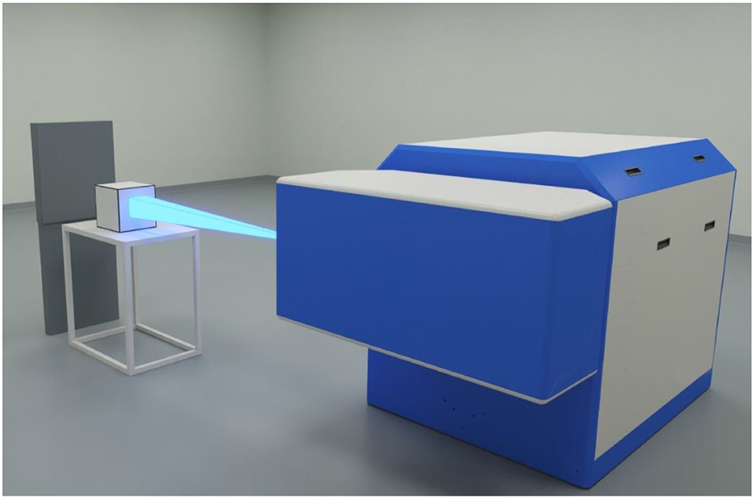
Figure 1. ElectronFlash.
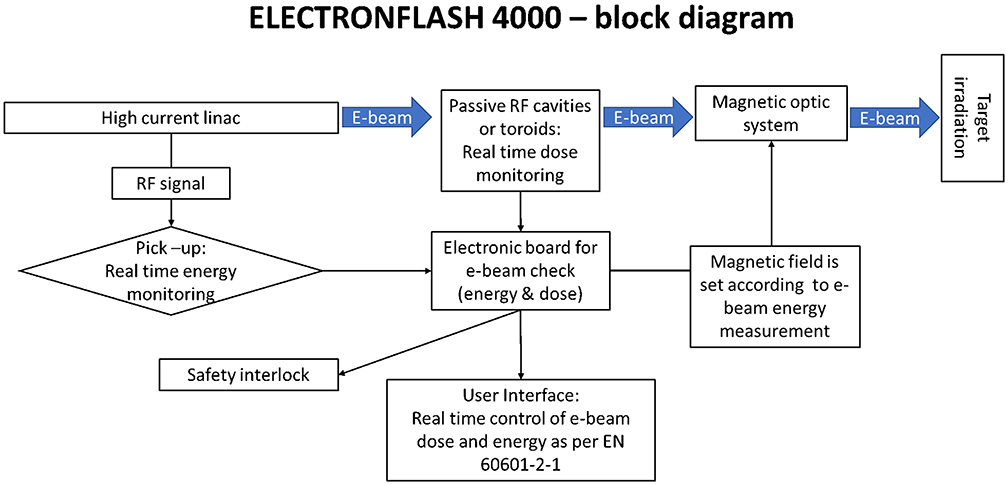
Figure 2. ElectronFlash block diagram.
The accelerating wave guide has been designed by adopting the radial focusing technique: the e-beam radial dynamics is guided by the electric field of the cavities and not by an external solenoid. This approach, though challenging from the manufacturing point of view, not only allows a better control with virtually no X-ray leakage, but also the design of a lighter and more compact system.
The accelerating waveguide concept is based on the experience gained by SIT staff in the design of IORT-dedicated linacs [29].
Beam dynamics simulations have been performed by La Sapienza SBAI Department (https://www.sbai.uniroma1.it/) in order to optimize the tank for high current beam. The guide is shown in Figure 3 together with some outputs of beam dynamics simulation performed with PARMELA code (https://laacg.lanl.gov/laacg/services/serv_codes.phtml). It is shown that no scattering happens between e-beam and the radiofrequency (RF in the following) cavities: e-beam radial dimensions are always smaller than the diameter hole (8 mm) of the RF cavities beam channel, as shown in Figure 3.
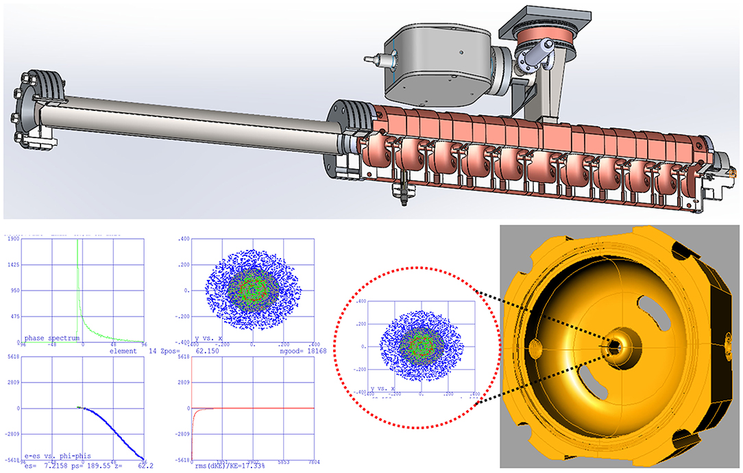
Figure 3. Accelerating tank and beam dynamics simulation.
A different approach has been implemented for e-beam collimation compared to the standard medical linac. Instead of using thick scattering foil, the beam is defocused by two quadrupoles into the desired field. Such approach provides several advantages for a linac operating in FLASH mode:
- Fluence transmission into the target is optimized, as long as the only element the e-beam scatters with is the thin titanium window that seals the vacuum tube.
- Due to the absence of thick scattering elements leakage radiation is minimized.
- Large/clinical fields are achievable by properly setting the quadrupoles current.
It is remarkable that such beam optic system implies that the ratio of the doses for two different fields F1 and F2 is given by:
where DF1 and DF2 are the delivered doses and SF1 and SF2 are the surfaces of the two fields.
In order to comply with the standard IEC 60601-2-1 [23], beam monitoring in the FLASH region requires not only a real time measurement of the beam current (which is proportional to the absorbed dose) but also a real-time check of the average energy of the beam.
The standard IEC 60601-2-1, in the paragraph 201.10.1.2.101.5 (“Selection and Display of Energy”) requires that:
“IRRADIATION shall be TERMINATED if the mean ENERGY, Ei, of the ELECTRONS striking:
[…]
- the ELECTRON RADIATION window deviates by more than ±20% or ± 2 MeV, whichever is the lesser during ELECTRON IRRADIATION, from the value of mean ENERGY that would occur under normal operating conditions for the selected energy and mode of operation.”
In a radiofrequency powered linac, the power generated by the RF source can be written as:
where WLINAC is the power absorbed by the accelerating waveguide and We−beam is the power absorbed by the beam itself. If the power absorbed by the e-beam becomes comparable with the power absorbed by the accelerating tank, e-beam current variation influences the beam energy.
Assuming a monochromatic spectrum,
the precise calculus of the power absorbed by the accelerating waveguide, WLINAC, can be performed as described in [30]; for an accelerating waveguide operating in the S band, designed for 10 MeV, WLINAC is around 2 MW.
The percentage energy variation of the electron beam can be roughly estimated as (refer to [30] for a detailed calculus).
In the abovementioned hypotheses, a beam current variation slightly >10% induces an energy variation >20%. It is therefore clear that a specific system for checking energy constancy is mandatory. Such system should operate independently with respect to the dose monitoring system.
The solution proposed is illustrated in Figure 4: e-beam energy can be real time monitored, pulse by pulse, by means of a signal taken by a pick-up positioned inside a RF cavity. The operation principle is briefly described; further details can be found in [30]. The total energy gain ΔKTOT in the accelerating waveguide is:
where NACC is the number of the accelerating cavities and ΔK is the energy gain per single cavity.
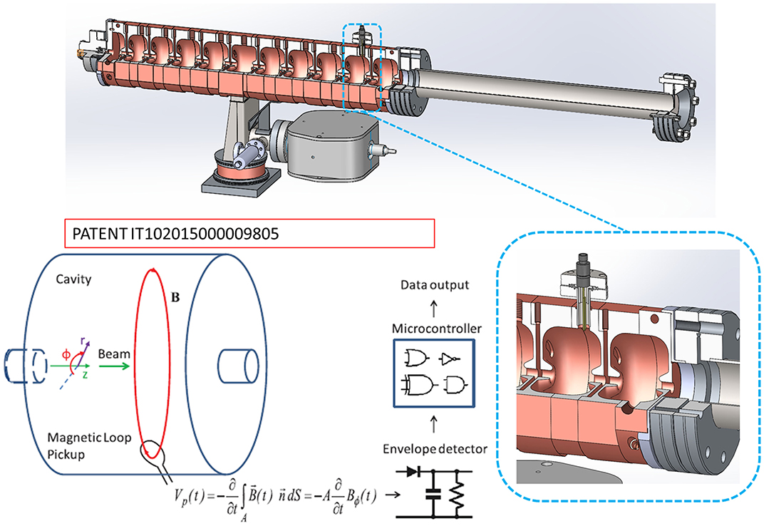
Figure 4. Energy real time measurement.
In general, ΔK ∝ E0 where E0 is the spatial average of the longitudinal electrical field along the cavity (at a fixed time, when e-beam is in phase with the field). Inside each cavity, the electric field has a fixed ratio respect to the magnetic field B. Therefore, the measurement of such field provides a real time, nondestructive measurement of the electric field E0 and, therefore, of overall energy of the accelerated e-beam [31]. The time derivative of the magnetic flux generated by B is measured through the pick-up shown in Figure 4 so that,
the speed of such system is determined by the electronic board maximum speed, as long as signal detection itself is luminal. Such technique provides an online and easy system for checking energy constancy, with a precision better than 5%.
Ionization chamber technology appears probably not adequate both for beam monitoring and dose measurements. There are, at least, two issues:
- Assuming the electrical field inside the ionization chamber not being affected by the one generated by the ionization, the current models [32] cannot describe properly the ionization chamber behavior;
- Response time of the chamber itself.
The dose monitor system must guarantee that the correct dose is delivered within the required tolerance levels. Furthermore, the dose monitor system should respond quickly enough to shut off the beam when the dose set is reached. The drift time of the electrons within an ionization chamber operating in FLASH regime is probably too slow to reach this goal; hence, new dose monitoring techniques will be required. A solution for overcoming all the issues related to ionization chamber operation in the FLASH region represents a change of paradigm. Fluence can be detected by means of in vacuum electrical measurements. Such techniques, widely adopted in high-energy physics, are still not common in medical linacs but represent indeed the most promising perspective.
The system EF has been designed in order to produce both FLASH and conventional dose rates. Therefore, a dual-dose monitoring system has been implemented (Figure 5) to allow an adequate fluence reading within a very broad range (0.01 cGy/p−40 Gy/p) for FLASH and conventional modality.
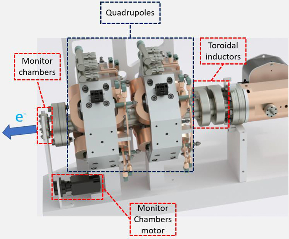
Figure 5. e-beam monitoring system.
In FLASH modality, e-beam output is monitored by means of two toroidal inductors and monitor chambers are positioned outside the beam line; in conventional modality, the monitor chambers are inserted along the beam line, as illustrated in Figure 5. Because of their sensitivity of 10 V/A, the toroidal inductors provide a fast and robust signal up to few milliamperes of beam current. The dual hardware allows to get a very good signal to noise ratio in every operational mode.
A possible alternative to toroidal inductors is represented by a passive resonant cavity, as proposed by Leggieri et al. [33]: the beam, while crossing the cavity, induces a resonant electromagnetic field that can be detected through a pick-up. The voltage at pick-up terminations is representative of the real time beam current and is elaborated, by a microcontroller system, for the output monitoring.
The passive resonant cavity reading, for a given beam current, can be varied by changing parameters such as its internal shape and material [34]; however, an optimized monitor system capable of appropriately monitoring a beam in a wide range (1–100 mA for ElectronFlash) would necessarily require at least two different cavities, each optimized for a specific range. Furthermore, this solution requires the a fine tuning of each cavity and its thermostating at the same linac temperature. On the other hand, the dual monitoring system implemented in ElectronFlash adopts two different technologies (monitor chambers and toroidal inductors), achieving in principle the same overall accuracy. Monitoring system performances will be experimentally verified and validated after ElectronFlash installation.
The dose-rate DR generated by a pulsed electron beam is directly proportional to the dose-per-pulse Dp
where PRF is the pulse repetition frequency.
At PRF smaller than 100 Hz, all the dosimeters analyzed have a shorter signal collection time with respect to the repetition time of the pulses (≥ 10 ms), and, consequently, the saturation is influenced only by the dose-per-pulse (duration of the pulse is around 2.5 μs).
Considering a standard frequency of 30 Hz, in order to reach FLASH dose-rate values (> 40 Gy/s) it is necessary to produce dose-per-pulse higher than 1 Gy/p. This value is at least one or two orders of magnitude greater than the dose-per-pulse produced respectively by IORT and conventional linacs, for which the most common online dosimeters were designed, produced, and tested.
Absolute dose in a PMMA phantom was measured with a 10-MeV electron beam produced by a NOVAC11 mobile accelerator. The dose-per-pulse has been increased by a minimum of 5 cGy/p in reference conditions up to 40 Gy/p by modifying the collimation system as described in detail in section Experimental Setup. In order to investigate dosimeter saturation problems in FLASH dose-per-pulse conditions, different types of detectors were irradiated at increasing dose-per-pulse up to FLASH values (40 Gy/p), using as reference the measurements performed with independent dose-rate radiochromic films dosimeters.
Currently, IORT dedicated linacs are characterized by a significantly high dose-per-pulse [26, 27], typically around 5 cGy/p, with a pulse repetition frequency ranging from 1 to 30 Hz: dose rates higher than conventional ones are achievable. This feature, together with the very simple beam collimation system, makes the system itself particularly attracting for a preliminary study of the dosimeters behavior in FLASH mode.
In order to produce an electron beam with dose-rate values proper of a FLASH beam (>1 Gy/p), a preexisting dedicated IORT electron linear accelerator has been considered, the NOVAC11.
NOVAC11 provides 4 nominal electron energies (4, 6, 8, 10 MeV) and the electron beam collimation system is purely passive: NOVAC11 does not use any scattering foil for beam broadening that is obtained by means of a hard-docking collimation system. Such collimation system consists of two separated polymethylmethacrylate (PMMA) cylindrical applicators that can be directly attached to the radiant head. The applicator is made of two parts: an upper part called applicator holder or upper applicator—directly mounted to the radiant head—and the terminal part called terminal applicator, which is connected to the upper one by means of a ring nut. The PMMA applicators have 5 mm wall thickness, internal diameter ranging from 3 to 10 cm, and a flat or beveled end. The length of the applicators determines the Source Surface Distance (SSD), which is 80 cm for the reference applicator with a diameter of 10 cm. Thanks to this relatively simple architecture, it is possible to obtain several collimation configurations (Figure 6). Every configuration leads to a different SSD and, consequently, to a different resulting dose-per-pulse.
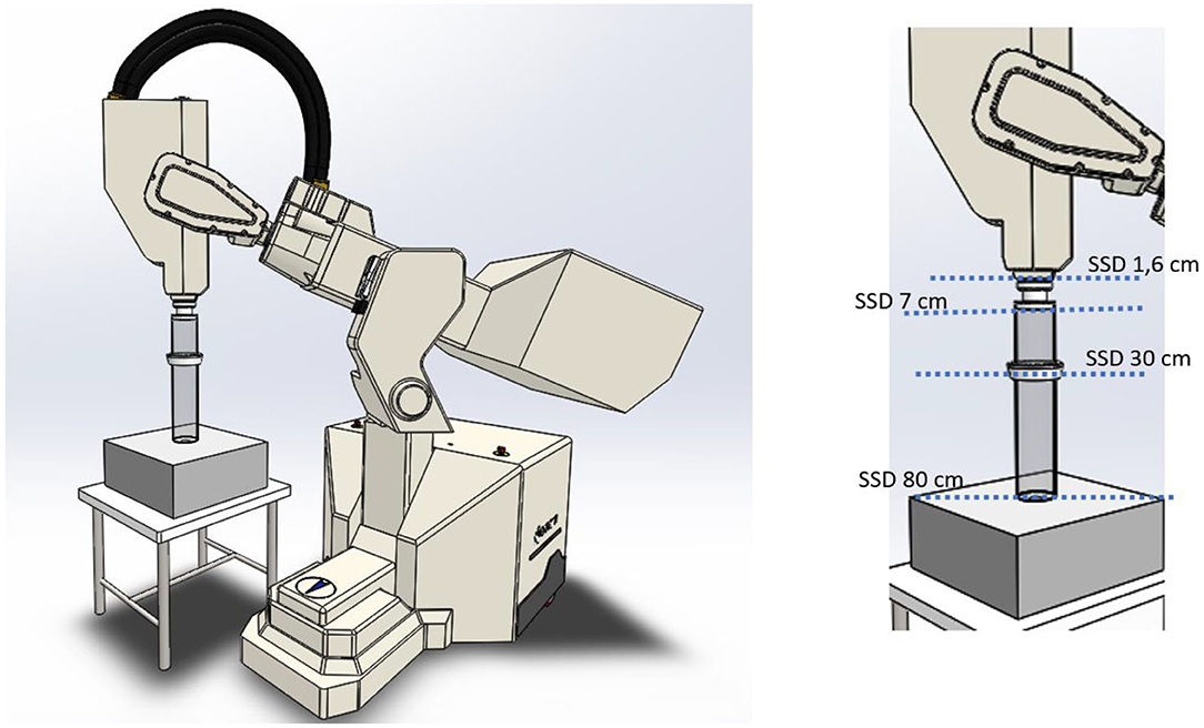
Figure 6. NOVAC11: FLASH irradiation setup.
The different setups are obtained as follows:
- Clinical reference configuration: upper and terminal applicator connected to the chambers housing (SSD 80 cm).
- Upper applicator connected to the monitor chambers housing (SSD 30 cm).
- Only monitor chambers housing (SSD 7 cm).
- Dismounted monitor chambers (SSD 1.6 cm).
In Figure 7, such configurations, together with the possible maximum achievable dose-rates, are detailed.
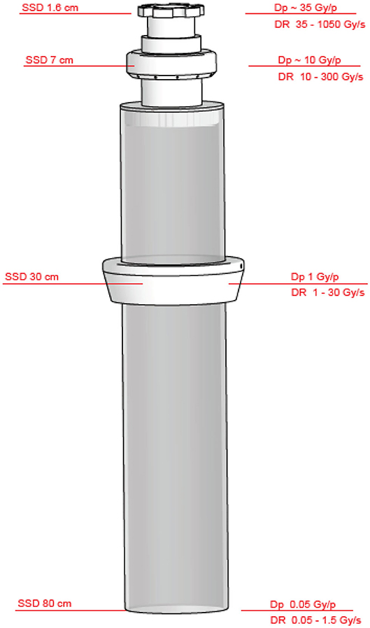
Figure 7. Beam collimation and achievable SSDs, maximum dose rates, and dose per pulse achievable with NOVAC11 (applicator Ø10 cm).
A more detailed description on how Novac can be converted into a FLASH research machine, and its dosimetric characterization is available in [28].
Even though NOVAC11 is not able to produce a FLASH beam suitable for radiobiological experiments, it is however possible, by changing the SSD, to reach a very high dose-per-pulse beam inside a small spot homogenous enough for the irradiation of small dosimeters like those considered in the present study. Due to the unsuitability of the dosimeters commonly used in the clinical practice—as they show saturation problems approaching to FLASH dose-rates—reference dosimetry was performed using radiochromic films. Radiochromic films are dose-rate independent, hence they allow an extensive dosimetric characterization of the e-beam. The GAFCHROMIC EBT-XD [35] calibration curve has been obtained by irradiating the films with increasing dose values in the range from 0 to 150 Gy, by positioning the films in a PMMA solid phantom at R100 depth. The calibration fitting function, according to the optimized protocol for calibration and dosimetry [36] distributed by Ashland, is represented by the rational function:
where A, B, and C are parameters of the function, and f (x) and x are, respectively, the absorbed dose in cGy and the color value in 16 bpch [36], as read by the RGB scanner Epson 1680 Pro. Cross-calibration between optical densities and absolute dose-response has been performed by means of an ionization chamber in a conventional dose-rate range.
The detectors to be tested have been chosen among the commercially available ones adequate for measuring the beam produced by IORT linacs. IORT linac is the highest dose-per-pulse machine among the currently available medical linacs (3–13 cGy/p against 0.07–0.3 cGy/p). Radiochromic films (GAFCHROMIC EBT-XD) irradiated within a PMMA phantom have been considered as reference.
The online dosimetric systems tested were:
- PTW TW34045 Advanced Markus® Electron Chamber [37].
- PTW TM60017 Dosimetry Diode E [38].
- PTW TW60019 microDiamond [39].
- DoseVue DoseWire™ Series 100 scintillating fiber [40].
DoseWire is an inorganic scintillator detector consisting of a hemispherical 0.1 cc active volume of europium-doped yttrium oxide. The emission light is in the range 600–650 nm. If the dosimeter is used in its standard counter mode, the minimum time between two consecutive events, in order that the system is able to discriminate them, is of the order of 20 ns.
Calibration curve calculated by the dedicated software FilmQA Pro is shown in Figure 8.
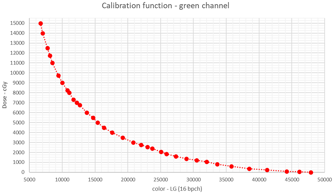
Figure 8. Calibration fitting function in the green channel, as calculated by FilmQA Pro.
The focus of the present work is the saturation phenomena of the dosimetric systems tested. As previously discussed, saturation phenomena are primarily caused by the value of the dose-per-pulse Dp. At a value of 1 cGy/p, either the dosimeters cannot show saturation phenomena (scintillator, diode, and microdiamond [26]) or their saturation can be correctly calculated (ionization chambers [24, 25, 27]). Then, we have considered the ratio between the reading of each dosimeter at varying the dose-per-pulse and its reading at Dp = 1 cGy/p; such ratio is called DrR (dosimeter reading ratio) in Figure 9.
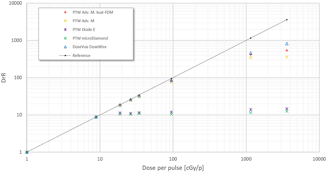
Figure 9. DrR vs. dose per pulse.
DrR is defined as
DrR combined standard uncertainty can be estimated as . The quantity is evaluated as the standard deviation over five consecutive measurements and results always around or <0.7%; therefore, the combined standard uncertainty is smaller than 1% and it is not shown in the graphs of Figures 9, 10.
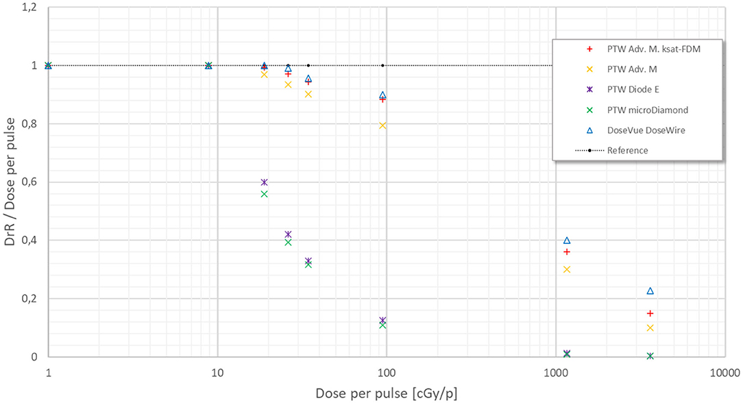
Figure 10. DrR/dose-per-pulse vs. dose-per-pulse.
The graphs are displayed in a double log plot in order to facilitate their visualization. Such approach offers an immediate and qualitative picture of dosimeters behavior in a very wide range. Ideally, for a dosimeter not affected by any saturation phenomena, DrR is a line with angular coefficient equal to 1, as for radiochromic films (reference black line in Figure 9).
In Figure 10, the ratio between DrR and the dose-per-pulse as measured by radiochromic films is reported.
The measurements performed offer a clear, even though preliminary, picture of the inadequacy of the current dosimetric equipment when operating in the FLASH region.
PTW Diode E and microDiamond semiconductors show a nonreversible saturation beyond a threshold around 15 cGy/p. DoseVue DoseWire™ Series 100 scintillators show a negligible saturation up to 1 Gy/p, it increases significantly up to at least 11 Gy/p and it reaches a cutoff value between 11 and 36 Gy/p.
PTW Advanced Markus® Ionization chamber saturation cannot be adequately described according to the methods reported in literature for values above 30 cGy/p: the Laitano et al. [25] model does not provide any solution while the Di Martino model [24] greatly underestimates the recombination effect, as shown in Figure 10. Such experimental results are consistent with the data reported by McManus et al. [41], even they adopt a Very High Energy Electrons (VHEE) system and the maximum dose per pulse is 5.26 Gy/p.
The recent experimental evidence of the FLASH effect obtained in vivo has generated great interest within the radiotherapy community due to its potential and important clinical implications.
Before the radiobiological mechanisms underlying this effect could be fully understood, several technological and scientific challenges must be faced.
Such challenges affect the irradiator as well as the measuring devices.
This work presents the design of an electron linac dedicated to ultra-high dose rate experiments, ElectronFlash [42].
The specific problems and requirements generated by the acceleration and monitoring of a Flash electron beam are discussed, and some possible solutions are presented. The first EF unit will be installed in Institut Curie during summer 2020; a complete characterization of its performances will be presented in a future manuscript.
While electron linacs may be the simplest implementation for a Flash irradiator, they may represent the most complex challenge for dosimetry. Radiofrequency (RF)-powered electron linacs produce a heavily pulsed beam, with a dose per pulse up to 40 Gy/p or higher, with a pulse repetition frequency (PRF) up to 400 Hz.
On the other hand, proton and carbon ion accelerators produce a continuous or almost continuous beam; even when reaching the ultra-high dose rate region, their dosimetric characterization can be performed adopting the common dosimetric protocols, provided that saturation is determined with a different approach (the recombination theory for proton and light ions has been presented and discussed in [43]).
Thus, while Flash proton beams may be successfully measured within the framework of the current protocols [44], even with some adjustment in the determination of recombination factor [43], Flash electron beams may require a complete change of paradigm. The experimental results with ionization chambers, which confirm the data presented by McManus et al. [41], show the inadequacy of the current approaches [24, 25, 44] in determining the chamber saturation.
The analysis performed in Appendix, Section 1—Ionization Chambers shows that, for electron beams around 1 Gy/p or higher, the electric field generated by ionized charges exceeds the one generated by the polarization applied and, therefore, cannot be neglected. This may lead to the need of introducing a different, more complex model, capable of describing properly the chamber ionization behavior in the ultra-high dose rate region.
This may lead to the need of introducing a different and more complex model capable of describing properly the chamber ionization behavior in the ultra-high dose rate region.
Other dosimeters were studied: semiconductor diodes and scintillators.
The tested semiconductor dosimeters have a total saturation at a precise dose-per-pulse value (cutoff value) around 15 cGy/p that is significantly lower than the FLASH dose-per-pulse values. Hence, semiconductor dosimeters currently available on the market cannot be used.
The tested scintillator shows a dose-per-pulse response as expected, with the saturation increasing with the dose-per-pulse, reaching a cutoff value between 11 and 36 Gy/p, where saturation is no longer correctable.
The scintillator was used in its standard mode (counter mode); nevertheless, the analysis performed in Appendix, Section 2—Scintillators suggests that a better behavior could be reached if the system works in integrator mode, introducing a correction for the deadtime.
Additional studies are required for assessing this result properly.
The present work offers some possible solutions in the design of an electron Flash linac and raises many questions about its dosimetric characterization which remain to be answered.
A new linac concept has been described, a system capable of accelerating and monitoring the fluence needed for reaching the Flash beam dose rates studied so far [1, 2, 4, 5] and even beyond; the specific solutions implemented were discussed and its performances will be described in a future work after its installation in Institut Curie.
However, the Flash electron beam dosimetric characterization still poses unsolved challenges, for online dosimeters, both concerning relative and absolute dosimetry.
In particular, the current description of ionization chambers behavior in the Flash region for electron beams is not adequate. When dose-per-pulse is around or above 1 Gy/p, the shielding effect of the electric field generated by the ionized charges, during their movement toward the two opposite electrodes, is no longer negligible. Therefore, the current recombination models [24, 25, 44], which totally neglect such effect, do not properly describe saturation phenomena in FLASH dose-per-pulse regime. New theoretical models must be developed and experimentally validated before ionization chambers could be used for FLASH beam dosimetry.
In conclusion, it is possible to state that there is a lot of research to be done before the dosimetric characterization of Flash electron beams will be fully understood.
The raw data supporting the conclusions of this article will be made available by the authors, without undue reservation.
FM and GF designed the study. FM, LGr, and GF wrote the manuscript. LF, LGi, MM, and LP performed the simulations shown in Figure 3. All authors discussed the manuscript and performed the experimental job. All authors contributed to the article and approved the submitted version.
Sordina IORT Technology has provided funds for open access fees.
SB, SD, MD, GF, LGr, and MP are SIT employees; GF is a SIT shareholder. Nonetheless, they confirm that this does not affect the design and preparation of the paper neither the analysis nor the interpretation of data.
The remaining authors declare that the research was conducted in the absence of any commercial or financial relationships that could be construed as a potential conflict of interest.
The handling editor declared a past supervisory role with one of the authors MP.
The authors thank Ilaria Breglia for the English revision of the paper and Emiliano D'Agostino, DoseVue founder, for his helpful scientific comments and discussion.
The Supplementary Material for this article can be found online at: https://www.frontiersin.org/articles/10.3389/fphy.2020.570697/full#supplementary-material
1. Fouillade C, Favaudon V, Vozenin M-C, Romeo P-H, Bourhis J, Verrelle P, et al. Les promesses du haut débit de dose en radiothérapie. Bull Cancer (Paris). (2017) 104:380–4. doi: 10.1016/j.bulcan.2017.01.012
2. Favaudon V, Caplier L, Monceau V, Pouzoulet F, Sayarath M, Fouillade C, et al. Ultrahigh dose-rate FLASH irradiation increases the differential response between normal and tumor tissue in mice. Sci Transl Med. (2014) 6:245ra93–ra93. doi: 10.1126/scitranslmed.3008973
3. Montay-Gruel P, Petersson K, Jaccard M, Boivin G, Germond J-F, Petit B, et al. Irradiation in a flash: Unique sparing of memory in mice after whole brain irradiation with dose rates above 100 Gy/s. Radiother Oncol. (2017) 124:365–9. doi: 10.1016/j.radonc.2017.05.003
4. Bourhis J, Montay-Gruel P, Gonçalves Jorge P, Bailat C, Petit B, Ollivier J, et al. Clinical translation of FLASH radiotherapy: why and how? Radiother Oncol. (2019) 139:11–7. doi: 10.1016/j.radonc.2019.04.008
5. Bourhis J, Sozzi WJ, Jorge PG, Gaide O, Bailat C, Duclos F, et al. Treatment of a first patient with FLASH-radiotherapy. Radiother Oncol. (2019) 139:18–22. doi: 10.1016/j.radonc.2019.06.019
6. Buonanno M, Grilj V, Brenner DJ. Biological effects in normal cells exposed to FLASH dose rate protons. Radiother Oncol. (2019) 139:51–5. doi: 10.1016/j.radonc.2019.02.009
7. Simmons DA, Lartey FM, Schüler E, Rafat M, King G, Kim A, et al. Reduced cognitive deficits after FLASH irradiation of whole mouse brain are associated with less hippocampal dendritic spine loss and neuroinflammation. Radiother Oncol. (2019) 139:4–10. doi: 10.1016/j.radonc.2019.06.006
8. Montay-Gruel P, Acharya MM, Petersson K, Alikhani L, Yakkala C, Allen BD, et al. Long-term neurocognitive benefits of FLASH radiotherapy driven by reduced reactive oxygen species. Proc Natl Acad Sci U S A. (2019) 116:10943–51. doi: 10.1073/pnas.1901777116
9. Vozenin M-C, Baumann M, Coppes RP, Bourhis J. FLASH radiotherapy International Workshop. Radiother Oncol. (2019) 139:1–3. doi: 10.1016/j.radonc.2019.07.020
10. Freeman T. FLASH Radiotherapy: From Preclinical Promise to the First Human Treatment. Phys World (2019). Available online at: https://physicsworld.com/a/flash-radiotherapy-from-preclinical-promise-to-the-first-human-treatment/
11. Durante M, Brauer-Krisch E, Hill M. Faster and safer? FLASH ultra-high dose rate in radiotherapy. Br J Radiol. (2018) 91:20170628. doi: 10.1259/bjr.20170628
12. Spitz DR, Buettner GR, Petronek MS, St-Aubin JJ, Flynn RT, Waldron TJ, et al. An integrated physico-chemical approach for explaining the differential impact of FLASH versus conventional dose rate irradiation on cancer and normal tissue responses. Radiother Oncol. (2019) 139:23–7. doi: 10.1016/j.radonc.2019.03.028
13. Pratx G, Kapp DS. A computational model of radiolytic oxygen depletion during FLASH irradiation and its effect on the oxygen enhancement ratio. Phys Med Biol. (2019) 64:185005. doi: 10.1088/1361-6560/ab3769
14. Spitz DR, Buettner GR, Limoli CL. Response to letter regarding “An integrated physico-chemical approach for explaining the differential impact of FLASH versus conventional dose rate irradiation on cancer and normal tissue responses.” Radiother Oncol. (2019) 139:64–5. doi: 10.1016/j.radonc.2019.07.009
15. Maxim PG, Keall P, Cai J. FLASH radiotherapy: newsflash or flash in the pan? Med Phys. (2019) 46:4287–90. doi: 10.1002/mp.13685
16. Jolly S, Owen H, Schippers M, Welsch C. Technical challenges for FLASH proton therapy. Phys Med. (2020) 78:71–82. doi: 10.1016/j.ejmp.2020.08.005
17. Esplen NM, Mendonca MS, Bazalova-Carter M. Physics and biology of ultrahigh dose-rate (FLASH) radiotherapy: a topical review. Phys Med Biol. (2020). doi: 10.1088/1361-6560/abaa28. [Epub ahead of print].
18. Lansonneur P, Favaudon V, Heinrich S, Fouillade C, Verrelle P, De Marzi L. Simulation and experimental validation of a prototype electron beam linear accelerator for preclinical studies. Phys Med. (2019) 60:50–7. doi: 10.1016/j.ejmp.2019.03.016
19. Jaccard M, Durán MT, Petersson K, Germond J-F, Liger P, Vozenin M-C, et al. High dose-per-pulse electron beam dosimetry: commissioning of the Oriatron eRT6 prototype linear accelerator for preclinical use. Med Phys. (2018) 45:863–74. doi: 10.1002/mp.12713
20. Jorge PG, Jaccard M, Petersson K, Gondré M, Durán MT, Desorgher L, et al. Dosimetric and preparation procedures for irradiating biological models with pulsed electron beam at ultra-high dose-rate. Radiother Oncol. (2019) 139:34–9. doi: 10.1016/j.radonc.2019.05.004
21. Lempart M, Blad B, Adrian G, Bäck S, Knöös T, Ceberg C, et al. Modifying a clinical linear accelerator for delivery of ultra-high dose rate irradiation. Radiother Oncol. (2019) 139:40–5. doi: 10.1016/j.radonc.2019.01.031
22. National Council on Radiation Protection and Measurements. Structural Shielding Design and Evaluation for Megavoltage X- and Gamma-Ray Radiotherapy Facilities: Recommendations of the National Council on Radiation Protection and Measurements Bethesda, MD: National Council on Radiation Protection and Measurements (2005).
23. Medical Electrical Equipment - Part 2-1: Particular Requirements for the Basic Safety and Essential Performance of Electron Accelerators in the Range 1 MeV to 50 MeV.
24. Di Martino F, Giannelli M, Traino AC, Lazzeri M. Ion recombination correction for very high dose-per-pulse high-energy electron beams: ksat evaluation for very high dose-per-pulse electron-beams. Med Phys. (2005) 32:2204–10. doi: 10.1118/1.1940167
25. Laitano RF, Guerra AS, Pimpinella M, Caporali C, Petrucci A. Charge collection efficiency in ionization chambers exposed to electron beams with high dose per pulse. Phys Med Biol. (2006) 51:6419–36. doi: 10.1088/0031-9155/51/24/009
26. Pimpinella M, Andreoli S, De Angelis C, Della Monaca S, D'Arienzo M, Menegotti L. Output factor measurement in high dose-per-pulse IORT electron beams. Phys Med. (2019) 61:94–102. doi: 10.1016/j.ejmp.2019.04.021
27. Scalchi P, Ciccotelli A, Felici G, Petrucci A, Massafra R, Piazzi V, et al. Use of parallel-plate ionization chambers in reference dosimetry of NOVAC and LIAC ® mobile electron linear accelerators for intraoperative radiotherapy: a multi-center survey. Med Phys. (2017) 44:321–32. doi: 10.1002/mp.12020
28. Felici G, Barca P, Barone S, Bortoli E, Borgheresi R, De Stefano S, et al. Transforming an IORT Linac Into a FLASH Research Machine: procedure and dosimetric characterization. Front Phys. (2020) 8:374. doi: 10.3389/fphy.2020.00374
29. Felici G, DiFrancesco M, De Stefano S, Grasso L. 349. IORT dedicated linac radiation protection: a novel approach. Phys Med. (2018) 56:271–2. doi: 10.1016/j.ejmp.2018.04.357
31. Dispositivo di Misura dell'energia del Fascio di Particelle in Uscita da Acceleratori IORT. Italian Patent IT102015000009805
32. Khan FM, Gibbons JP. Khan's the Physics of Radiation Therapy. Philadelphia, PA: Lippincott Williams & Wilkins/Wolters Kluwer (2014).
33. Leggieri A, Passi D, di Paolo F, Ciccotelli A, De Stefano S, Marangoni F, et al. Real-time beam monitor for charged particle medical accelerators. IEEE Trans Nucl Sci. (2016) 63:869–77. doi: 10.1109/TNS.2015.2504403
34. Stevens P, Van Hoof F, Messens E, Holvoet M, Verellen D. IORT & stray radiation: comparison of 2 commercial linacs. in: Electronic Poster: Physics Track: Radiation Protection, Secondary Tumour Induction and Low Dose (Incl. Imaging) (2019) 133(Suppl 1):S909S910. doi: 10.1016/S0167-8140(19)32111-5
35. Gafchromic™ radiotherapy films Chemistry: Radiochromic Film. Available online at: https://www.ashland.com/industries/medical/medical-radiation-dosimetry/gafchromic-radiotherapy-films#
36. Lewis D, Micke A, Yu X, Chan MF. An efficient protocol for radiochromic film dosimetry combining calibration and measurement in a single scan: efficient protocol for radiochromic film dosimetry. Med Phys. (2012) 39:6339–50. doi: 10.1118/1.4754797
37. Advanced Markus® Electron Chamber. Available online at: https://www.ptwdosimetry.com/en/products/advanced-markus-electron-chamber/
38. Dosimetry Diode E Type 60017. Available online at: https://www.rpdinc.com/ptw-dosimetry-diode-981.html
39. microDiamond. Available online at: https://www.ptwdosimetry.com/en/products/microdiamond/
40. DoseVue DoseWire™ Series 100. Available online at: https://www.dosevue.com/index.php/product-line
41. McManus M, Romano F, Lee ND, Farabolini W, Gilardi A, Royle G, et al. The challenge of ionisation chamber dosimetry in ultra-short pulsed high dose-rate Very High Energy Electron beams. Sci Rep. (2020) 10:9089. doi: 10.1038/s41598-020-65819-y
42. Dispositivo Per Il Trattamento Radioterapico Di Malati Oncologici. Italian Patent Application N. 102019000016760 19.09.2019
43. Rossomme S, Delor A, Lorentini S, Vidal M, Brons S, Jäkel O, et al. Three-voltage linear method to determine ion recombination in proton and light-ion beams. Phys Med Biol. (2020) 65:045015. doi: 10.1088/1361-6560/ab3779
Keywords: radiotherapy, FLASH effect, FLASH electron linac, beam monitoring system, saturation problems
Citation: Di Martino F, Barca P, Barone S, Bortoli E, Borgheresi R, De Stefano S, Di Francesco M, Faillace L, Giuliano L, Grasso L, Linsalata S, Marfisi D, Migliorati M, Pacitti M, Palumbo L and Felici G (2020) FLASH Radiotherapy With Electrons: Issues Related to the Production, Monitoring, and Dosimetric Characterization of the Beam. Front. Phys. 8:570697. doi: 10.3389/fphy.2020.570697
Received: 08 June 2020; Accepted: 22 September 2020;
Published: 02 November 2020.
Edited by:
Vincenzo Patera, Sapienza University of Rome, ItalyReviewed by:
Alessio Sarti, Sapienza University of Rome, ItalyCopyright © 2020 Di Martino, Barca, Barone, Bortoli, Borgheresi, De Stefano, Di Francesco, Faillace, Giuliano, Grasso, Linsalata, Marfisi, Migliorati, Pacitti, Palumbo and Felici. This is an open-access article distributed under the terms of the Creative Commons Attribution License (CC BY). The use, distribution or reproduction in other forums is permitted, provided the original author(s) and the copyright owner(s) are credited and that the original publication in this journal is cited, in accordance with accepted academic practice. No use, distribution or reproduction is permitted which does not comply with these terms.
*Correspondence: Fabio Di Martino, Zi5kaW1hcnRpbm9AYW8tcGlzYS50b3NjYW5hLml0; Giuseppe Felici, Z2l1c2VwcGUuZmVsaWNpQHNvcmRpbmEuY29t
Disclaimer: All claims expressed in this article are solely those of the authors and do not necessarily represent those of their affiliated organizations, or those of the publisher, the editors and the reviewers. Any product that may be evaluated in this article or claim that may be made by its manufacturer is not guaranteed or endorsed by the publisher.
Research integrity at Frontiers
Learn more about the work of our research integrity team to safeguard the quality of each article we publish.