 L. Bottura
 E. Felcini
 V. Ferrero
 E. Fiorina
 V. Monaco4,3
 F. Pennazio
 P. Cerello
- 1CERN, Geneva, Switzerland
- 2EPFL, Lausanne, Switzerland
- 3INFN, Sezione di Torino, Torino, Italy
- 4Department of Physics, University of Torino, Torino, Italy
The design of a particle therapy system that integrates an innovative beam delivery concept based on a static toroidal gantry and an imaging configuration suitable for beam and online range monitoring is proposed and discussed. Such approach would provide a compact and cost-effective layout, with a highly flexible and fast beam delivery, single particle counting capability for fast measurement of beam fluence and position and a precise real time verification of the compliance between the treatment delivery and its prescription. The gantry configuration is discussed, presenting an analysis of the residual magnetic field in the bore and of the feasibility of irradiating a realistic target volume. Moreover, the expected performance of the PET-based range monitor is assessed through Monte Carlo simulations, showing a precision in the reconstruction of the activity distribution from a clinical treatment plan better than the state-of-the-art devices. The feasibility of the proposed design is then discussed through an assessment of the technological improvements required to actually start the construction and commissioning of a system prototype.
1. Introduction
Particle therapy exploits the energy deposition pattern of ion beams, with the Bragg peak at the end of range, to minimise the unwanted dose to healthy tissues. However, the cost, complexity, and large footprint of the installations have somehow limited its diffusion; the lack of well-established real-time verification tools to precisely verify the compliance between the planned and delivered treatment is an additional limitation to the full exploitation of its clinical potential.
Operating particle therapy facilities implement beam delivery through either a fixed beam line [1] or a mobile gantry [2], a rotating transfer line able to deliver the required dose from virtually any direction.
Fixed beam lines are relatively simple to implement with respect to gantries, but the beam incident angle on the patient in some conditions does not allow an optimal design of the dose distribution and the treatment field geometry; also, fixed lines require moving the patients, with both translations and rotations, in order to complete a full treatment session.
Rotating gantries overcome this limitation, at the cost of a more complex and technically challenging implementation. The gantry itself and the supporting mechanical structure are remarkably large and bulky, both for protons and, especially, for heavier ions. While in the proton case commercial solutions are in the range of 4–5 m in radius and up to 200 tons in weight, existing carbon ion gantries can exceed the 14 m in diameter and 600 tons in weight [3]. Making use of superconducting magnets, it is possible to increase the magnetic field and reduce the footprint of the machine down to about 9 m and 300 tons [4].
Several new concepts of rotating gantries have been proposed recently, making use of combined function [5, 6] or large acceptance magnets [7, 8] to reduce their size.
In any case, the gantry rotation requires high mechanical precision and increases the treatment session duration; also the rotation of cryogenic parts and the ramping of the magnetic field create challenging operating conditions for the superconducting systems, particularly sensitive to unwanted transitions to normal-conducting state. As a consequence, most of the treatments are delivered from only a small subset of the possible incident angles [9], suggesting that a decrease in the gantry structure complexity might be achieved at the cost of decreasing the possible treatment angles.
As reported in [10] one of the driving factors of particle therapy facilities is the gantry footprint, as well as the size of the building required to contain it. The design and construction of more compact and lighter gantries is of utmost importance to facilitate the accessibility of particle therapy to the largest number of patients.
Regardless of the selected solution for beam delivery, beam monitoring functionality is essential and is usually integrated in the nozzle. A limitation in beam monitoring arises from the technology, based on gas detectors, currently employed to measure the number of delivered particles and the beam position [11]. The slow collection time of gas detectors, of the order of hundreds of μs, and their poor sensitivity, with a minimum threshold of the order of thousands of protons, prevent their use in fast delivery modality, which is required, for example, to improve the treatment of moving targets, for which shorter response times and higher sensitivity are needed [12].
New implementations based on solid state detectors, that could overcome these limitations, are being investigated: in particular the short pulse duration in thin sensors can be exploited to directly count the number of delivered particles, instead of measuring it indirectly from the charge produced in a gas. Silicon detectors with moderate internal gain (Low-Gain Avalanche Detectors, LGAD [13]) can be used to compensate for the reduction of signal in small thicknesses.
Segmented LGAD detectors optimized for timing measurements, also known as Ultra Fast Silicon Detectors (UFSD) [14], could concurrently provide position and time information for each beam particle with extremely high resolutions: nowadays the time resolution reached by 45 μm thick UFSD sensors for Minimum ionizing Particles is about 27 ps [15].
Online range monitoring is a crucial step to provide early treatment assessment in particle therapy. Intrinsic uncertainties in the beam range limit the exploitation of the advantages of particle therapy: for example, current treatment plans for protons implement a safety margin up to 3.5% + 3 mm [16]. In order to reduce this margin, a better control on range uncertainties is mandatory. Moreover, over the course of a treatment, often lasting several weeks, morphological changes can occur in the tissues and require a reassessment of the treatment plan: range monitoring tools can effectively identify if and when such reevaluation should take place.
The issue of online range monitoring can be addressed by taking advantage of passive signals originating from beam-induced effects: prompt photon production from nuclear de-excitation, back-to-back monochromatic photons from electron-positron annihilation following β+ decay and, for treatment with ion beams, protons from beam fragmentation are strictly correlated to the beam path, and can therefore be exploited to indirectly monitor the delivered dose. In particular, β+ emitting isotopes have been thoroughly investigated with Positron Emission Tomography (PET) techniques. Due to tissue composition mostly short-lived emitting isotopes are produced (e.g., 11C and 15O, with half-lives of about 20 and 2 min, respectively): therefore, PET measurements are best performed simultaneously to the beam irradiation (in-beam PET). This is also a key factor to minimise the biological washout, and therefore maximise the correlation between the delivered dose and the measured activity. The production yield of positron emitters is also low, resulting in a much smaller number of detected events with respect to nuclear medicine PET. These attributes imply that high sensitivity scanners are required for in-beam-PET measurements; moreover, the scanner geometry is constrained by the requirement of not interfering with the passage of the beam and the patient positioning and handling subsystems. Although geometries with full angular coverage have been proposed [17], past and present in-beam PET scanners feature open geometries and limited angular coverage: the BASTEI scanner [18], BOLPs-RGp [19], LAPD [20], the dual-ring OpenPET [21] and DOPET [22], as well as the state-of-the-art INSIDE scanner [23].
As of now, however, only few results were obtained in real time in a clinical environment with proton beams: tests on a small number of patients show that prompt gamma imaging [24] provides an accuracy in range verification that is better than the range uncertainty margin set in the treatment plans, while in-beam PET provides a range agreement within 1 mm between consecutive delivery sessions [25] and in the comparison of simulations to data [26].
We discuss in the following the concept design of an innovative system that would allow hybrid in-vivo real-time high-precision imaging thanks to the combination of a static toroidal gantry, a single particle beam counting device and a hybrid range monitoring system, providing a lightweight, cost effective and highly performant solution. We then focus on a specific implementation of a prototype to be used for proton treatment delivery and present the results of our first simulations of the response of a PET detector as online range monitor in the GaToroid layout when a treatment plan is delivered in a clinical setting.
2. Materials and Methods
The heart of the proposed design is a radically new gantry concept [27], based on a superconducting toroidal magnet generating an axially symmetrical field, that allows focusing beams of different energies on the same point.
The static gantry will preserve the advantage of rotating gantries, allowing to deliver the beam from many directions, with a much simpler and lightweight circular layout, consisting of a toroidal magnet operated in steady state conditions. The magnet coils are arranged so as to form a large number of beam channels with windows, corresponding to the pre-selected subset of beam delivery directions. Hence, the gantry does not need to rotate, and can be conveniently built using superconductors, resulting in dimensions that are a factor two to four smaller than those of state-of-the-art facilities.
The inner part of the static gantry will host both the beam delivery monitor and the online treatment verification system.
The beam monitoring system, made of multiple LGAD silicon detectors, would be positioned either on each beam window or on an internal rotating nozzle.
PET rings, installed either on both sides of the beam delivery windows or, in case of a single rotating beam monitor, in a ring with a gap in which the beam monitor itself would be mounted, would cover a large fraction of the solid angle, increasing both the field of view and the precision on the 3D activity map reconstruction with respect to presently available systems. In both options, sufficient statistics for reconstructing the beam-induced activity distribution would be collected in a short time and geometrical artefacts related to the limited angular coverage would be minimised.
Gantry
GaToroid represents a novel gantry concept for particle therapy, based on the use of an axially symmetric magnetic field generated by toroidal coils to bend and focus the particle beam. Such a gantry allows the dose delivery from a discrete number of angles, depending on the magnetic design.
This machine is conceived to work in steady-state, with no rotation of major mechanical components and no variations of the magnetic field. These features properly suit the use of superconductive technology, simplifying cryogenics stability, as well as remarkably increasing the intensity of the generated magnetic field.
The coils can be designed to have a very large acceptance, able to cover the complete range of treatment energies [28], i.e. from 70 to 250 MeV for protons and from 120 to 430 MeV/u for carbon ions, without changing the current or field. The Vector Magnet, an upstream bending magnet, rotating or combined vertical/horizontal, is used to steer the particles into the gantry with a proper angle, depending on the beam rigidity and the required treatment directions.
In the present work, we will focus our attention on a GaToroid for proton beams, constituted by 16 coils and the corresponding beam windows between the coils. Such a toroidal magnet configuration, discussed in detail in Ref. [29], is characterized by an inner free bore diameter of 0.8 m and an outer diameter of 3.3 m, resulting in a total mass of about 12 tons, including the main mechanical supports. The torus resulting from the optimization is presented in Figure 1, together with a schematic representation of a human for size comparison.
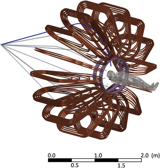
FIGURE 1. Representation of the GaToroid coil configuration for the beam delivery together with two PET rings used for the range monitoring simulations (case 1 in the following). The shape of the patient is used for size comparison. The beam lines start diverging after the vector magnet, that directs them toward the GaToroid with the appropriate angles.
The selected configuration is considered so far the most suitable to address the magnetic design challenges, allow the proper incorporation of the solid state beam monitoring devices and PET detectors and it would be suitable for building a first prototype. The use of superconductors operating in steady-state high fields (Β > 3T) remarkably reduces the footprint and the weight of the gantry in comparison with the state of the art. The magnet was designed to allow the use of both Low (LTS) and High (HTS) Temperature Superconductors, limiting the peak field to about 8T. Considering the former option, Nb-Ti would be a simple and effective choice, given the maturity of the technology and the relatively low price of the material. As for the latter, the use of superconductors above liquid helium temperature is an intriguing, yet challenging proposal, and the possibility to use Rare-earth Barium Copper Oxide (ReBCO) conductors is being investigated.
At the proposed magnetic field intensity, HTS would allow to operate in simpler cryogenics conditions, i.e. helium gas at 20 K, reducing cooling cost and power consumption. On the other hand, the use of HTS in liquid helium, i.e., 4.2 K, would open the possibility for a further increase of magnetic field beyond 10 T, with a drastic reduction of the gantry footprint and weight, but also an increase of complexity in terms of mechanics and quench protection.
Figure 2 shows the number of beam entrance windows (i.e., directions) from which any given point in a 20 cm diameter cylinder is reachable with the proposed configuration. The beam windows, shown in gray thick lines, have a size of about 10·10 cm2. Considering a SAD (Source-to-Axis Distance) of 4 m, necessary to limit the superficial dose increase [30], the maximum divergence of the beam during the scanning is 0.7°. With these geometric specifications the centered innermost disk of 11 cm diameter, highlighted in red, can be reached from 16 directions. The outermost disk, enclosed by a red line, shows a possible coverage of 20 cm diameter. The target volume can be reached at the isocenter from any of the beam windows (Figure 2A), while non-isocentric targets could be covered by using selected beam windows (Figure 2B).
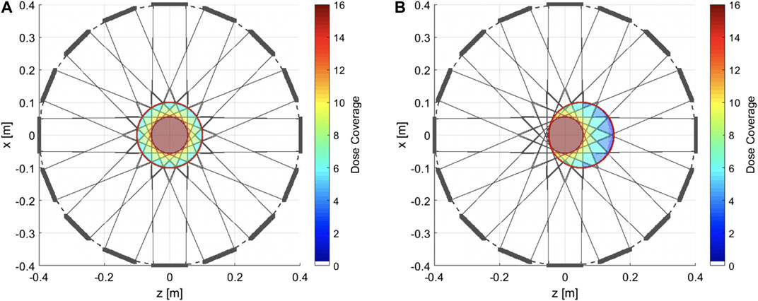
FIGURE 2. Beam coverage map. Beam exit windows are represented by the gray thick lines, in a Gatoroid configuration with 16 coils and an 80 cm diameter bore. For each beam window, the beam coverage area is drawn (light gray lines). (A) A cylindrical target volume of 20 cm diameter is highlighted at the isocenter. The color map indicates the number of beam windows from which the target volume can be accessed. (B) For non-isocentric targets, the same volume can be reached, with the limitation of fewer beam windows available.
Due to the axisymmetric configuration of the coils, the magnetic field at the isocentre, calculated with Field2017 [31] using a direct Biot-Savart method on the plane transversal to the toroidal axis around the isocenter location, is below the critical threshold for instrumentation and humans safety (order of μT). Similarly, the magnetic field rapidly decays with the radius inside the bore and at 30 cm radius is in the order of 10 mT.
In case of a loss of symmetry, for instance due to a short-circuit in a coil, the magnetic field strongly penetrates inside the bore exceeding hundreds of mT close to the patient region. For this reason, the quench protection system of the superconducting torus considers the simultaneous discharge of all the coils on external resistors [29].
Beam Monitoring
Segmented LGAD detectors with dedicated fast electronics are a promising option to overcome the limitation of gas detectors nowadays used for beam monitoring in charge particle therapy and would allow new delivery schemes with enhanced speed, sensitivity, spatial and time resolutions. Solid state detectors would be the natural choice for a monitoring device to be positioned in a region close to the GaToroid coils, where the performance of traditional gas detectors could be affected by the residual magnetic field, shown in Figure 3. The field residual values in the vicinity of the beam windows, where the beam and range monitor would be installed, drops quickly to zero.
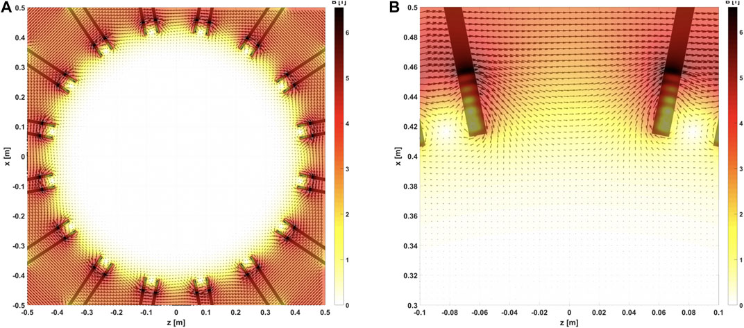
FIGURE 3. (A) Map of the magnetic field inside the bore (80 cm diameter) volume. The field value, when exiting the coils, drops quickly to values in the order of μT. (B) Zoom on the transition volume between the coils and the bore. The magnetic field in the beam and range monitor volumes, at 40 cm radius, is about 0.7 T, and drops to 10 mT at about 30 cm.
Preliminary results from test of 50 μm thick LGAD silicon sensors segmented in strips show that the number of particles of a therapeutic beam can be measured with a maximum error of 1% up to a flux of more than 108 p/(cm2s), limited by pile-up effects at higher fluxes, and that a fast online measurement of the beam energy for each spot can be obtained with the required clinical accuracy with time of flight techniques exploiting the high time resolution of the LGAD technology [32]. However, a measurement of the number of beam particles up to therapeutic fluxes of 1010 p/(cm2s) or more can be achieved only with silicon sensors segmented in pixels.
The main difficulties in designing silicon detectors for beam monitoring in the clinical practice are related to the technology complexity, high cost, and radiation resistance of large area pixelated silicon sensors and of their readout electronics. For this reason, the technological choice for the beam monitoring devices is still open to several possibilities, including traditional ionization chambers in case the time schedule and the budget of the prototype construction did not fit the time and costs required for the development of LGAD detectors. However, it should be remarked that the technology selected for the beam monitoring will be an important feature in defining the speed and precision of the delivery schemes that could be adopted with the GaToroid system. In addition, the time resolution of LGAD design could be exploited to enhance the capabilities of the range monitoring devices integrated in the gantry, while ionization chambers do not provide useful timing information.
Independently of the technological choice, the beam monitoring detectors will match the beam delivery windows foreseen by the GaToroid prototype design and will have to meet all the requirements for their use in clinical practice.
Online Range Monitoring
The GaToroid design, thanks to its circular symmetry, allows for the simple integration of a PET-based range monitoring system. In this work, we investigate two different configurations. The first one (case 1) is an open geometry consisting of two individual rings, shifted in the axial direction and positioned on each side of the GaToroid beam delivery windows. A similar geometry was proposed in Ref. [33], where it was shown how an axially-shifted dual ring detector could be suitable for in-beam-PET monitoring, as the image quality is almost independent of the width of the gap between the two rings, with uniform spatial resolution in the trans-axial direction, but a decreasing resolution in the axial direction as the gap width increases.
The second geometry (case 2) features a single-ring design, to be installed on a rotating structure inside the gantry, comprising a gap for the integration of the beam monitor. An additional geometry comprising a single ring with no gaps (case 0), is simulated as the reference case. All geometries, shown in Figure 4, have a 0.8 m diameter that fits the gantry design.
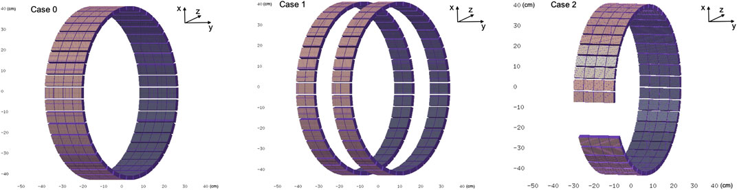
FIGURE 4. Solid model of the proposed PET detector geometries to be integrated within the GaToroid system. Case 0: single ring geometry, reference. Case 1: static dual ring open geometry, with the PET detectors positioned on each side of the beam entrance windows. Case 2: dynamic single ring geometry, to be mounted on a rotating structure inside the gantry, with a gap for the beam path.
The reconstruction performances corresponding to the proposed geometries were assessed with simulations based on the FLUKA Monte Carlo simulation tool [34, 35]. Lutetium-based state-of-the-art scintillating modules are considered as PET detectors elements, each of them made of 16·16 pixels (3.1·3.1·20 mm3, with 3.2 mm pitch), coupled one-to-one to Silicon PhotoMultiplier tiles. Case 1 and case 2 configurations include 176 (44·2 module arrays per ring) and 164 (41·4 module arrays) PET detector modules, respectively. For the reference case 176 modules, organized in 44 · 4 arrays, are simulated. Each detector module has an overall dimension of 52.1 · 52.1 · 21 mm3. Modules belonging to the same ring are distanced by 2 mm along the axial direction. The air gap between the two PET rings presented in case 1 is of 106.2 mm, corresponding to the overall dimension of each PET ring. As for case 2, the opening for the beam passage corresponds to about 16 cm length, which is compatible with the GaToroid beam window dimension.
Multiple scattering processes, electronic stopping power, energy loss fluctuations and nuclear reaction chains are modeled in the simulation [36], with positron and electron ranges traced down to 100 keV. The energy and interaction time of the detected events are smeared with a Gaussian distribution, considering a 15% dE/E and 300 ps FWHM timing resolution. A filtering algorithm is then used to search for events in a 2.7 ns coincidence window.
As benchmark, a homogeneous activity distribution corresponding to 106 annihilation events was simulated inside a 5 · 7 · 5 cm3 water phantom to assess the imaging performances of the proposed geometries (Figure 5).
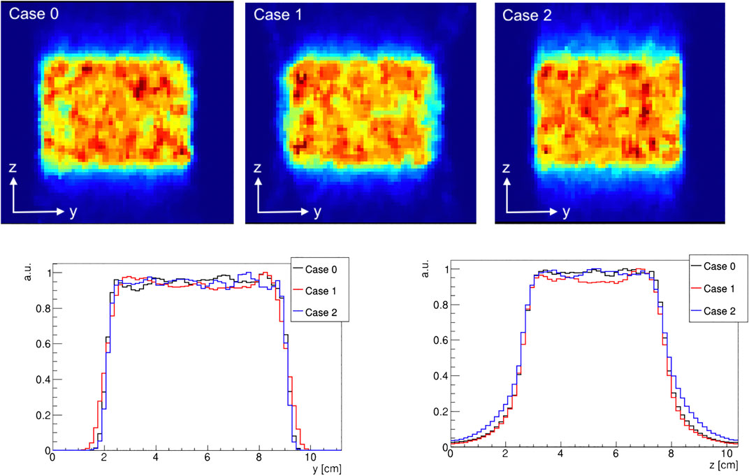
FIGURE 5. central slice in the (y, z) plane of a reconstructed homogeneous activity distribution for case 0, case 1, and case 2 (top). The corresponding activity profiles along the y and z directions, evaluated at the central slice (bottom).
Moreover, a proton treatment plan was simulated to assess the quality and precision of the reconstructed activity distribution. A clinical proton beam, modeled after the CNAO synchrotron facility clinical beam, was used for this purpose. The injected clinical treatment plan corresponds to the first field of a double-field adenoid cystic carcinoma (ACC) treatment, with the delivery of a horizontal beam line with the beam entrance from the left side (see Figures 6 and 7). A total of 1.8 · 109 protons were simulated in the beam field, in the [62, 141] MeV energy range.
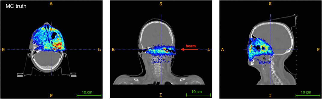
FIGURE 6. Axial (left), coronal (center) and sagittal (right) sections of the patient CT with the Monte Carlo activity distribution superimposed. The beam direction is shown for the coronal slice. A standard RAI coordinate system is considered.
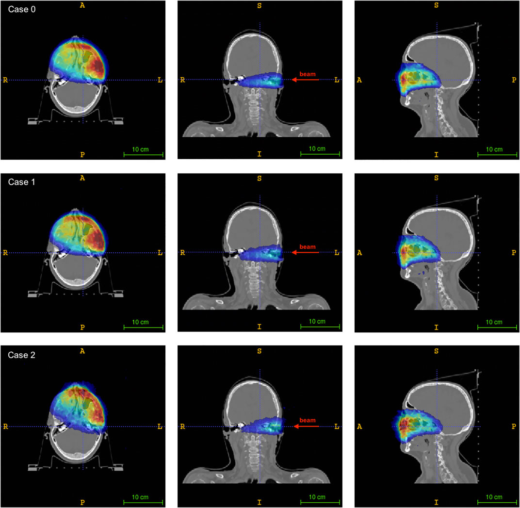
FIGURE 7. Axial (left), coronal (center) and sagittal (right) sections of the patient CT superimposed to the reconstructed activity distributions for the different geometries: case 0 (upper row), case 1 (central row), case 2 (lower row). The activity maps are normalized to their maximum intensity. The beam direction is shown for the coronal slice. A standard RAI coordinate system is considered.
The simulation tool was successfully validated both in controlled conditions (phantom tests) and in a clinical environment, providing an agreement with the data comparable to the variability of data from consecutive treatment sessions [26].
The activity images were reconstructed using an MLEM algorithm computed with Siddon’s single-ray-tracing system matrix which was validated on a previous work [37]. A 140 · 70 · 165 Field of View (FOV), with a pixel size of 1.6 mm, was used. Due to the missing projections in the case 1 and 2 geometries, the image quality is expected to worsen with respect to the reference condition (case 0).
3. Results
The present work focuses on the expected performance of the real time imaging system, by analysing different PET configurations integrated in the gantry, whose delivery configuration has already been discussed in detail in Ref. [28]. The beam monitoring design parameters are somehow set by the size of the beam entrance windows in the gantry; the technology choice will be addressed later on, in view of the construction of a prototype, based on results of ongoing R&D studies.
PET Image Quality Assessment
An assessment of the imaging performance of each considered geometry was carried out considering the reconstructed activity distribution coming from the simulation of a homogeneously activated 5 · 7 · 5 cm3 water phantom. The number of coincidences detected for each case is reported in Table 1. As expected, case 1 has the smallest number of coincidences, due to the larger gap and therefore larger number of missing projections that lead to a decrease in the number of detected events, while the reference case reports the highest. Still, the detected number of coincidences is of the same order of magnitude, with a minimal difference due to the diverse geometry, that does not significantly change the reconstructed activity distribution among the considered cases.
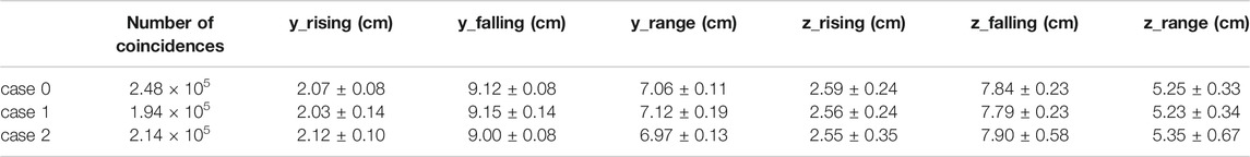
TABLE 1. Number of coincidences and range parameters of the activity profile in the y and z direction for a simulated 5 × 7 × 5 cm3 homogeneous activity. The reconstructed range matches the expected value within the error, for both projections and for all the configurations.
The reconstructed activity distributions and their profiles are shown in Figure 5, normalized to their maximum value: case 1 and 2 show slight image artefacts with respect to the reference case, due to truncation effects in the axial direction for case 1 and in the azimuthal one for case 2.
A comparison was performed on the activity profiles along the axial axis y and trans-axial axis z. The profiles were calculated by considering a rectangular area of 3 · 3 cm2 in the plane transverse to the preferred direction: for the z profile, a rectangular area at the center of the (x, y) plane is considered; similarly, for the y profile a rectangular area at the center of the (x, z) plane is considered. The rising and falling edges of the activity profile were fitted with a sigmoidal function as described in Ref. [23]. The inflection points of the sigmoidal fits were thus used to identify the beginning and the end of the distribution, calculating the activity range as the difference between the two. Results, reported in Table 1, show that the range values, both in the axial direction y and in the trans-axial direction z, are compatible, within the error, with the nominal values.
Clinical Treatment Plan Simulation
Figure 6 shows the axial (left), coronal (center) and sagittal (right) views of the patient CT superimposed with the activity distribution of the treatment plan under consideration, as obtained from the Monte Carlo simulation. The central slice of the corresponding reconstructed activity maps for each of the considered geometries are reported in Figure 7, with all the images shown in Right-to-Left, Anterior-to-Posterior, Inferior-to-Superior (RAI) coordinates.
A good visual comparison is found between the reconstructed activity distributions and the Monte Carlo truth, with the absence of strong image artefacts which are typically found in dual-head geometry detectors [37] that can hamper image quality and therefore the range assessment. A preliminary comparison between the reconstructed activity maps was done by considering the activity profiles along the beam direction (see for reference the coronal slice in Figure 7). The profiles, calculated considering a 7 · 7 voxels area (i.e., about 1 cm2) at the center of the (x, y) plane, are shown in Figure 8. The number of coincidences found for each case, and the rising and falling edges, calculated as the inflection points of a sigmoidal function, are reported in Table 2 for each profile. Even though a small difference is appreciated between the number of events detected by each of the simulated PET configurations, results show an excellent agreement between both case 1 and case 2 with the reference case 0, confirming the feasibility of using either geometry to implement online treatment monitoring in the GaToroid static gantry.
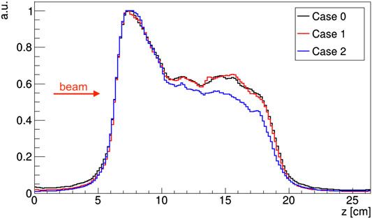
FIGURE 8. Activity profiles of a proton treatment plan evaluated along the beam direction for the considered PET geometry configurations. Profiles are normalized to their maximum.
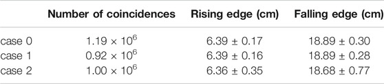
TABLE 2. Rising and falling edge defining the activity profile distribution for each of the considered PET geometries.
4. Discussion
The proposed design addresses in an innovative and integrated way the three key components that are necessary to fulfill particle therapy's promise of high-precision cancer treatment coupled to minimum damage to healthy tissue: beam delivery, dose monitoring and treatment verification.
Although a final technical design of the proposed system is not ready yet, the focus of this manuscript is on the description of the concept and on the evaluation of the expected performance of the imaging system to be integrated in GaToroid.
GaToroid is a gantry design concept that completely changes the approach to the beam delivery: the recently patented [38] lightweight, static toroidal gantry will allow a very precise beam modulation coupled to a very fast delivery time. The delivery of typical treatment plans can thus be quicker and simpler, while retaining the flexibility of firing the beam from many directions.
Moreover, the static configuration also allows a much lighter footprint, with remarkably smaller size, lower weight and lower cost, compared to existing gantries.
These advantages come at the price of restricting the set of delivery angles, since the entrance windows only cover a fraction of the azimuthal angle, with the rest taken by the coils. However, the design optimisation, in terms of bore size, number of coils, beam windows size will focus on maximising the angular acceptance for the incoming beam.
Beam monitoring is currently based on ionization chambers, a solid technology but a limiting factor for more performing delivery schemes requiring higher speed, sensitivity, spatial and time resolution. The development of LGAD thin silicon sensors offers the possibility to design innovative monitoring detectors that would overcome many limitations of gas chambers, opening at the same time the possibility to exploit extremely accurate time information. GaToroid allows the implementation of both options, and at the present stage no decision has been made in view of the design and implementation of a prototype system yet.
High precision range monitoring by means of in-vivo real time imaging is crucial in order to achieve full control of the treatment delivery and implement adaptive strategies in particle therapy. The few tests performed in clinical conditions show promising - but not optimized - results: with a gamma camera only the 1D beam profile along its delivery direction is measured [24], with two flat in-beam PET heads, the 3D activity distribution is reconstructed with limited statistics and a modest precision on the vertical coordinate [25].
We propose a PET-based online range monitoring, which is easily integrated in the GaToroid static configuration, that allows a ring-like layout similar to standard commercial scanners and, by means of a (nearly) full azimuthal angular coverage, will both enhance the statistics and limit the effect of geometry-related artefacts in the reconstruction.
The simulations of the delivery of a clinical treatment plan for adenoid cystic carcinoma provide a high quality 3D activity map, with no significant artefact, for both the PET configurations considered in the study,confirming the suitability of the proposed design.
In view of the choice of the beam monitoring technology, LGADs present an interesting option, as they would provide time-of-flight information, which, as already proposed by a previous study [39], could be combined to PET-based photon detection to implement a prompt-gamma-timing analysis. By coupling 3D activity maps and prompt-gamma distributions, the combination of the LGAD beam monitor and the PET range monitor would be a hybrid imaging device.
Technology Readiness
Although the construction of a prototype implementing the proposed design could be started with presently existing technologies, some ongoing developments would allow important improvements in view of the design of a full size system.
HTS conductors represent one of the most challenging aspects of the GaToroid magnetic design. Rare-earth-based Barium Copper Oxide (ReBCO) conductors are nowadays deeply investigated for high field application, such as toroidal fusion magnets [40, 41], particle accelerator magnets [42] and even for traditional rotating gantries [43]. While already providing the possibility of working well above the liquid helium temperature in a magnetic field of about 10 T, HTS conductors still present technological limits and challenges, such as insufficient field quality, not established quench protection techniques and limited amount of industrial manufacturing, inadequate for series production and costs reduction.
The ongoing development of GaToroid HTS coils will tackle these technical problems, for example by further investigating insulated windings with stacked tapes and Non or Partially-Insulated [44, 45] configurations for such large magnets. Beyond the cable topology and the insulation, effective and robust solutions for joints between grades and pancake layers are crucial aspects for the magnet design. At the same time, simulation tools and experimental validation are challenging aspects of HTS quench protection and must be faced to propose a solid and reliable machine for particle therapy.
Furthermore, the use of this kind of conductors for medical applications can also contribute to drive the ReBCO market toward a price reduction and a much wider spread, as was for Nb-Ti in MRI in the last decades.
For beam monitoring, the choice of segmented silicon detectors based on the LGAD technology naturally matches the requirements of the GaToroid design. However, this technology still has to face many challenges, starting from the need of a segmentation in small pixels to cope with the fluxes of therapeutic beams when the detectors are operated in counting mode. A high number of channels is required for the electronics, that must be bump-bonded to the sensor pads, and at the same time the total material thickness must be kept low enough to avoid significant beam perturbations. Another issue to be addressed for the use of LGAD detectors for beam monitoring is their limited radiation resistance, which was recently improved [46], in particular in view of their applications in high energy physics experiments; further progress is expected in the near future. For all the above mentioned reasons, the technology choice for implementing the beam monitoring functionality is still open.
However, the use of LGAD detectors would allow to implement more sophisticated analysis tools, giving access to the imaging of fast-decaying isotopes [47, 48], i.e., isotopes whose half life is in the ns-ms time-scale. As shown in a previous work by some of the authors [39], if a background rejection method based on data acquired in the inter-bunch period is implemented so as to discriminate only fast-decaying isotopes data, the activity range shows a stronger and more linear correlation to the primary particle range than longer-decaying isotopes, therefore yielding an enhanced detector sensitivity and range detection precision. Indeed, the real-time information collected within a few tens of milliseconds at a single beam-spot scale minimizes the long-lived contributions accumulated from previous spots that often correspond to different ranges.
Also, the timing information provided by LGAD detectors can be used to provide a start signal that, combined with a stop given by PET detectors, would generate a Time-Of-Flight (TOF) spectrum that could be analyzed with the Prompt Gamma Timing (PGT) technique [39, 49]. The TOF depends on the particle beam path and the photon emission point, therefore correlating the measured spectrum to the range in the delivered treatment. Moreover, prompt-gammas are emitted on a ps-scale, yielding a stronger correlation to the beam path than any distribution obtained measuring very-short- (i.e., shorter than the spill) or short-lived (i.e., mostly 11C and 15O) in-beam PET isotopes.
State-of-the-art PET detectors and electronics [50] can measure photons with a time resolution of the order of 100 ps; on the other hand, a single PET detector has a smaller active volume and energy resolution worse than a system optimised for photons in the MeV range. As shown in a preliminary feasibility study [39], it is in principle possible to implement PGT measurements with a PET detector. With a large angular coverage, as for the proposed in-beam PET scanner configuration, the information obtained by prompt photons can be exploited, as long as it is integrated with the position-dependent measurements of each detector. An algorithm designed for this purpose is in an advanced development stage, and will be the object of a future publication. Preliminary simulation results [51] show that the proposed in-beam PET scanner geometry could measure the prompt photons range with about 5 mm precision. The experimental implementation of the proposed technique will be definitely challenging, with the bottleneck being the high proton rate crossing the LGAD detector; however, the requirements for prompt gamma timing are less strict than for beam monitoring, where pile-up effects must be kept well under control. Although a full efficiency cannot be achieved at therapeutic rates, due to DAQ bandwidth limitations and to the overlap of signals very close in time (the last effect also depending on the beam time structure), the detection of these fast signals, combined with PET information, should lead to an enhanced correlation between the delivered dose and the measured distribution.
5. Conclusions
Large acceptance, steady-state configuration and superconducting magnets offer interesting reduction of size, weight and cost of gantries and related infrastructures, creating an attractive alternative to the state of the art. Furthermore, such a structural integration with beam and range monitoring represent an additional step toward compact gantries and single room facilities.
The GaToroid concept was presented, and a configuration suitable for proton beam delivery was defined, with an 80 cm diameter bore. The feasibility of irradiating a realistic target volume was assessed for the proposed configuration, and the residual magnetic field inside the bore was evaluated, in view of the choice of the dose delivery system. Moreover, an accurate simulation study of the expected performance of a PET-based range monitor, integrated in the gantry with different configurations, showed that a reliable, high resolution 3D activity image can be reconstructed from the delivery of a clinical treatment plan.
Further work will focus on defining the specifications of a beam monitor based on solid-state detectors, in terms of required area, pixelization, readout speed, sensitivity, spatial and flux measurement precision, and in developing the tools to exploit its time resolution to improve the treatment monitoring quality with the Prompt Gamma Timing (PGT) technique, in view of the final design of a GaToroid prototype with hybrid imaging capabilities.
Data Availability Statement
The raw data supporting the conclusions of this article will be made available by the authors, without undue reservation.
Author Contributions
LB, EFe and GDR designed and simulated the GaToroid configuration; VF, EFi, FP and VM defined the imaging system configuration, assessed the potential of a UFSDbased beam monitor device and implemented the simulation of the PET detector response in case of delivery of a clinical treatment plan; PC coordinated the development, in the framework of the ATTRACT/H2I2 project (see next section on Funding), and edited the manuscript.
Funding
This work is part of the ATTRACT project funded by the EC under Grant Agreement 777222, with project name Hybrid High-precision In-vivo Imaging in Particle Therapy (H2I2). The project is co-funded by the CERN Budget for Knowledge Transfer to Medical Applications.
Conflict of Interest
The authors declare that the research was conducted in the absence of any commercial or financial relationships that could be construed as a potential conflict of interest.
References
1. Rossi S. The national centre for oncological hadrontherapy (CNAO): status and perspectives. Phys Med (2015). 31:333–51. doi:10.1016/j.ejmp.2015.03.001.
2. Pedroni E, Bacher R, Blattmann H, Böhringer T, Coray A, Lomax A, et al. The 220-MeV proton therapy project at the Paul Scherrer Institute: conceptual design and practical realization. Med Phys (1995). 22(1):37–53.
3. Fuchs R, Weinrich U, Emde P. The heavy ion gantry of the HICAT facility (2004). Lucerne. EPAC-2004-THPLT033.
4. Iwata Y, Noda K, Shirai T, Murakami T, Furukawa T, Mori S, et al. Design of a superconducting rotating-gantry for heavy-ion therapy. Phys Rev Spec Top Accel Beams (2012). 15:044701. doi:10.1103/PhysRevSTAB.15.044701
5. Robin DS, Arbelaez D, Caspi S, Sun C, Sessler A, Wan W, et al. Superconducting Toroidal Combined-Function Magnet for a compact ion beam cancer therapy gantry. Nucl Instrum Methods Phys Res (2011). 659:484–93. doi:10.1016/j.nima.2011.08.049
6. Wan W. Alternating-gradient canted cosine theta superconducting magnets for future compact proton gantries. Phys Rev Spec Top Accel Beams (2015). 18:103501. doi:10.1103/PhysRevSTAB.18.103501
7. Trbojevic D. Carbon/proton therapy: a novel gantry design. Phys Rev Accel Beams (2007). 10:053503. doi:10.1103/PhysRevSTAB.10.053503
8. Gerbershagen A. A novel beam optics concept in a particle therapy gantry utilizing the advantages of superconducting magnets. Z Med Phys (2016). 26:224–37. doi:10.1016/j.zemedi.2016.03.006
9. Haberer T. The heidelberg ion beam therapy center, workshop: ideas and technologies for a next generation facility for medical research and therapy with ions (2018). Available at: https://indico.cern.ch/event/682210/contributions/2960999/attachments/1670825/2682144/Haberer_IONS2018_HITandMIT-Status_2018Jun19_public.pdf.
10. Yan S, Lu HM, Flanz J, Adams J, Trofimov A, Bortfeld T. Reassessment of the necessity of the proton gantry: analysis of beam orientations from 4332 treatments at the Massachusetts general hospital proton center over the past 10 years. Int J Radiat Oncol (2016). 95(1):224–33. doi:10.1016/j.ijrobp.2015.09.033
11. Giordanengo S, Donetti M, Garella MA, Marchetto F, Alampi G, Ansarinejad A, et al. Design and characterization of the beam monitor detectors of the Italian national center of oncological hadron-therapy (CNAO). Nucl Instrum Meth A (2013). 698:202–7. doi:10.1016/j.nima.2012.10.004
12. Farr JB, Flanz JB, Gerbershagen A, Moyers MF. New horizons in particle therapy systems. Med Phys (2018). 45(11): e953–83. doi:10.1002/mp.13193.
13. Sadrozinski HW, Ely S, Fadeyev V, Galloway Z, Ngo J, Parker C, et al. Ultra-fast silicon detectors. NIMA (2013). 730:226–231. doi:10.1016/j.nima.2013.06.033
14. Staiano A, Arcidiacono R, Boscardin M, Dalla Betta GF, Cartiglia N, Cenna F, et al. Development of ultra-fast silicon detectors for 4D tracking. J Inst Met (2017). 1017:C12012. doi:10.1088/1748-0221/12/12/C12012
15. Cartiglia N, Staiano A, Sola V, Arcidiacono R, Cirio R, Cenna F, et al. Beam test results of a 16 ps timing system based on ultra-fast silicon detectors. NIMA (2017). 850:83–88. doi:10.1016/j.nima.2017.01.021
16. Paganetti H. Range uncertainties in proton therapy and the role of Monte Carlo simulations. Phys Med Biol (2012). 57(11):R99–117. doi:10.1088/0031-9155/57/11/R99
17. Tashima H, Yoshida E, Inadama N, Nishikido F, Nakajima Y, Wakizaka H, et al. Development of a small single-ring OpenPET prototype with a novel transformable architecture, Phys Med Biol (2016). 61(4):1795–809. doi:10.1088/0031-9155/61/4/1795.
18. Enghardt W, Parodi K, Crespo P, Fiedler F, Pawelke J, Pönisch F. Dose quantification from in-beam positron emission tomography. Radiother Oncol (2004). 73(2):S96–98. doi:10.1016/S0167-8140(04)80024-0
19. Nishio T, Miyatake A, Ogino T, Nakagawa K, Saijo N, Esumi H. The development and clinical use of a beam on-line PET system mounted on a rotating gantry port in proton therapy. Int J Radiat Oncol Biol Phys (2010). 76(1):277–86. doi:10.1016/j.ijrobp.2009.05.065
20. Binet S, Bongrand A, Busato E, Force P, Guicheney C, Insa C, et al. Construction and first tests of an in-beam PET demonstrator dedicated to the ballistic control of hadrontherapy treatments with 65 MeV protons. IEEE Trans Radiat Plasma Med Sci (2018). 2(1):51–60. doi:10.1109/TRPMS.2017.2780447
21. Yoshida E, Tashima H, Shinaji T, Shimizu K, Wakizaka H, Mohammadi A, et al. Development of a whole-body dual ring OpenPET for in-beam PET. IEEE Trans Radiat Plasma Med Sci (2017). 4(1):293–300. doi:10.1109/TRPMS.2017.2703823
22. Topi A, Muraro S, Battistoni G, Belcari N, Bisogni MG, Camarlinghi N, et al. Monitoring proton therapy through in-beam PET: an experimental phantom study. IEEE Trans Radiat Plasma Med Sci (2020). 4(2):194–201. doi:10.1109/TRPMS.2019.2924036
23. Bisogni MG, Attili A, Battistoni G, Belcari N, Camarlinghi N, Cerello P, et al. INSIDE in-beam positron emission tomography system for particle range monitoring in hadrontherapy. J Med Imag (2017). 4(1):011005. doi:10.1117/1.JMI.4.1.011005
24. Xie Y, Bentefour EH, Janssens G, Smeets J, Vander Stappen F, Hotoiu L, et al. Prompt gamma Imaging for in vivo range verification of pencil beam scanning proton therapy. Int J Radiat Oncol Biol Phys (2017). 99(1):210–8. doi:10.1016/j.ijrobp.2017.04.027
25. Ferrero V, Fiorina E, Morrocchi M, Pennazio F, Baroni G, Battistoni G, et al. Online proton therapy monitoring: clinical test of a Silicon-photodetector-based in-beam PET. Sci Rep (2018). 8:4100. doi:10.1038/s41598-018-22325-6.
26. Belcari E, Ferrero V, Pennazio F, Baroni G, Battistoni G, Belcari N, et al. Monte Carlo simulation tool for online treatment monitoring in hadrontherapy with in-beam PET: a patient study. Phys Med (2018). 51:71–80. doi:10.1016/j.ejmp.2018.05.002.
27. Bottura L, Felcini E, De Rijk G, Dutoit B. GaToroid: a novel toroidal gantry for hadron therapy. Nucl Instrum Methods Phys Res (2020). 983:164588. doi:10.1016/j.nima.2020.164588
28. Felcini E, Bottura L, van Nugteren J, Gerbershagen A. Particle tracking and beam optics analysis on toroidal gantry for hadron therapy, submitted for publication to focus on early career researchers. Phys Med Biol (2020).
29. Felcini E, Bottura L, van Nugteren J, De Rijk G, Kirby G, Dutoit B. Magnetic design of a superconducting toroidal gantry for hadron therapy. IEEE Trans Appl Supercond 30(2020).
30. Pullia M, Lante V, Necchi M, Savazzi S, Moreno JO. Deliverable report JRA6.3 conceptual design of a carbon ion gantry. ULICE Union of Light Centres in Europe (2009).
31. Van Nugteren J Software development for the science and design behind superconducting magnet systems (2011). CERN Internship Report.
32. Vignati A, Donetti M, Fausti F, Ferrero M, Giordanengo S, Hammad Ali O, et al. Thin low gain avalanche detectors for particle therapy applications, proceedings of the mini-micro-nano dosimetry and innovative technologies in radiation oncology conference, 10-16 February 2020, north Wollongong, Australia. J Phys Conf 1662 (2020). 012035.
33. Yoshida E, Tashima H, Nishikido F, Yamaya T. Development of open-type PET scanners with single-ring and dual ring geometries. J Nucl Med (2016). 57:105.
34. Ferrari A, Sala P, Fassò A, Ranft J. FLUKA: a multi-particle transport code (program version 2005) (2005). Rep. SLAC-R-773. Available from: https://www.osti.gov/biblio/877507.
35. Böhlen TT, Cerutti F, Chin MPW, Fassò A, Ferrari A, Ortega PG, et al. The FLUKA code: developments and challenges for high energy and medical applications. NuclData Sheets (2014). 120:211–4. doi:10.1016/j.nds.2014.07.049
36. Battistoni G, Bauer J, Böhlen TT, Cerutti F, Chin MPW, Ortega PG, et al. The FLUKA code: an accurate simulation tool for particle therapy. Front Oncol (2016). 6:116. doi:10.3389/fonc.2016.00116
37. Ferrero V, Pennazio F, Cerello P, Fiorina E, Garbolino S, Monaco V, et al. Evaluation of in-beam PET treatment verification in proton therapy with different reconstruction methods. IEEE TRPMS (2020). 4(2):202–11. doi:10.1109/TRPMS.2019.2942713
38. Bottura L. A Gantry and apparatus for focussing beams of charged particles. WO2019/224215. (2019).
39. Ferrero V, Cerello P, Fiorina E, Monaco V, Rafecas M, Wheadon RJ, et al. Innovation in online hadrontherapy monitoring: an in-beam PET and prompt-gamma-timing combined device. NIMA (2019). 936:48–9. doi:10.1016/j.nima.2018.08.065
40. Sykes A, Costley AE, Windsor CG, Asunta O, Brittles G, Buxton P, et al. Compact fusion energy based on the spherical tokamak. Nucl Fusion (2018). 58(1):016039. doi:10.1088/1741-4326/aa8c8d
41. Whyte DG, Minervini J, LaBombard B, Marmar E, Bromberg L, Greenwald M. Smaller & sooner: exploiting high magnetic fields from new superconductors for a more attractive fusion energy development path. J Fusion Energy (2016). 35(1):41–53. doi:10.1007/s10894-015-0050-1
42. Kirby GA, van Nugteren J, Bajas H, Benda V, Ballarino A, Bajko M, et al. First cold powering test of REBCO roebel Wound coil for the EuCARD2 future magnet development project. IEEE Trans Appl Supercond (2017). 27(4):1–7. doi:10.1109/TASC.2017.2653204
43. Takayama S, Kiyanagi K, Yamaguchi A, Tasaki K, Kurusu T, Ishii Y, et al. Design of conduction-cooled HTS coils for a rotating gantry. Phys Procedia (2015). 67:879–84. doi:10.1016/j.phpro.2015.06.148
44. Hahn S, Park DK, Bascunan J, Iwasa Y. HTS pancake coils without turn-to-turn insulation. IEEE Trans Appl Supercond (2011). 21(3):1592–5. doi:10.1109/TASC.2010.2093492
45. Hahn S, Kim K, Kim K, Lee H, Iwasa Y. Current status of and challenges for no-insulation HTS winding technique. J Cryog Supercond Soc Jpn (2018). 53(1):2–9. doi:10.2221/jcsj.53.2
46. Cartiglia N, Sadrozinski H, Seiden A. Tracking particles at fluences 5-10⋅1E16 neq/cm2. In: Proceedings, 27th international workshop on vertex detectors (VERTEX 2018); 2018 Oct 21–26; Chennai, India. Vertex (2018). 9 p.
47. Miyatake A, Nishio T, Ogino T, Sajio N, Esumi H, Uesaka M. Measurement and verification of positron emitter nuclei generated at each treatment site by target nuclear fragment reactions in proton therapy. Med Phys. (2010). 37(8):4445–55. doi:10.1118/1.3462559
48. Dendooven P, Buitenhuis HJT, Diblen F, Heeres PN, Biegun AK, Fiedler F, et al. Short-lived positron emitters in beam-on PET imaging during proton therapy. Phys Med Biol (2015). 60(23):8923–47. doi:10.1088/0031-9155/60/23/8923
49. Golnik C, Fernando Hueso-González F, Müller A, Dendooven P, Enghardt W, Fiedler F, et al. Range assessment in particle therapy based on prompt gamma-ray timing measurements. Phys Med Biol (2014). 59(18):5399–422. doi:10.1088/0031-9155/59/18/5399
50. Bugalho R, Di Francesco A, Ferramacho L, Leong C, Niknejad T, Oliveira L, et al. Experimental results with TOFPET2 ASIC for time-f-flight applications. Nucl Instrum Methods Phys Res A (2018). 912:195–8. doi:10.1016/j.nima.2017.11.034
51. Bottura L, Felcini E, Ferrero V, Fiorina E, Monaco V, Pennazio F, et al. Hybrid high-precision in-vivo imaging in particle therapy (H2I2). (2020). Available from: https://attract-eu.com/wp-content/uploads/2019/05/H2I2.pdf.
Keywords: particle therapy, gantry, beam monitor, range monitor, treatment verification, PET, PGT
Citation: Bottura L, Felcini E, Ferrero V, Fiorina E, Monaco V, Pennazio F, de Rijk G and Cerello P (2020) Delivery, Beam and Range Monitoring in Particle Therapy in a Highly Innovative Integrated Design. Front. Phys. 8:566679. doi: 10.3389/fphy.2020.566679
Received: 28 May 2020; Accepted: 28 October 2020;
Published: 30 November 2020.
Edited by:
Yolanda Prezado, INSERM U1021 Signalisation normale et pathologique de l’embryon aux thérapies innovantes des cancers, FranceReviewed by:
Giacomo Cuttone, Laboratori Nazionali del Sud (INFN), ItalyDenis Dauvergne, Centre National de la Recherche Scientifique (CNRS), France
Copyright © 2020 Bottura, Felcini, Ferrero, Fiorina, Monaco, Pennazio, de Rijk and Cerello. This is an open-access article distributed under the terms of the Creative Commons Attribution License (CC BY). The use, distribution or reproduction in other forums is permitted, provided the original author(s) and the copyright owner(s) are credited and that the original publication in this journal is cited, in accordance with accepted academic practice. No use, distribution or reproduction is permitted which does not comply with these terms.
*Correspondence: P. Cerello, cGllcmdpb3JnaW8uY2VyZWxsb0B0by5pbmZuLml0