- 1Department of Mathematics, Division of Science and Technology, University of Education, Lahore, Pakistan
- 2Department of Mathematics, Dammam Community College, King Fahd University of Petroleum and Minerals, Dhahran, Saudi Arabia
The current investigation deals with the inclusion of solid particles in the flow of a non-Newtonian incompressible fluid passing through a symmetric, curved channel admitting flexible walls and exhibiting wavy characteristics for the passage of fluid. This analysis reflects the disease of white particles occurring in the flow of urine. The problem formulation is structured under the constraints of lubrication approach. The flow is considered to be laminar and steady by transforming the unsteady coordinates into wave frame coordinates. The governing equations have been formulated with the help of similarity transformations. The solution of boundary value problems has been handled by perturbation procedure. The analytical solutions for fluid and particulate phase velocities, mean flow rates, and pressure gradient profile have been presented, while a numerical treatment has been carried out for pressure rise. Analyses of fluid velocity and particulate suspension velocity, pressure gradient, and pressure rise curves under the variations of material parameters have been discussed by graphs. It is observed from this investigation that solid particles are curtailing the velocity and pressure of the liquid. It is also procured that the curvature of the channel also reduces the movement of the fluid and that the particulate suspension is occurring at the bottom of the container. It is very considerable that the increase in peristaltic pumping causes a decrease in the solid particle concentration. This theoretical analysis can help in curing the diseases like urinary tract infections (UTIs). The analysis may also be pertinent to the flow of other physiological liquids and industrial solicitation where peristaltic pumping is concerned.
Introduction
Peristaltic flows are produced by spreading waves along the exorable membranes of a conduit. These flows provide an efficient means for fluid transport and are therefore used in the physical simulation. In clinical and medical contexts, peristaltic flows are meant for the blood transport within tiny blood vessels or fabricated blood instruments. Fluid trapping and material reflux are the two wonderful aspects of peristaltic passages. They describe the development and flow of free transport, called bolus supply. These two factors are of major importance, as they can be responsible for blood circulation and transport of viruses. From the point of view of mechanical engineering, these phenomena highlight the complexity of the chosen apparatus, but also encourage the fundamental study of such flows. Studies of peristaltic phenomena have been reported in Bhatti et al. [1], Hussain et al. [2], and Riaz [3].
It is noticed that the instant flow studies are congested to Newtonian fluids. The non-Newtonian behavior of fluids is of greater concern in many areas of science and technology. In applications for electroosmosis, for example, test accumulation, discovery, blending, and division of different natural and synthetic species on a chip coordinated with fluidic siphons and valves, the liquid rheological conduct for the most part should be considered. Major comprehension of the non-Newtonian job in fluid transport through microchannels is imperative in accurately foreseeing the exhibition and qualities of microfluidic gadgets. Numerous specialists have researched the entry of non-Newtonian liquid through peristaltic component [4, 5].
The progression of particles in a liquid is a part of multiphase mechanism. Such studies are significant in different physical issues, for example, sedimentation, barometril aftermath, powder innovation, vaporized filtration, fluidization [6], debris and lunar streams, and so forth. Moreover, with the assistance of the continuum hypothesis of blends, it is anything but difficult to look at different assorted subjects, for example, the rheology of blood [7], dissemination of proteins, demeanor of particles in a respiratory tract, and swimming of microorganisms [8]. Besides, molecule portrayal is likewise a significant part in a generation of molecule, preparing, taking care of, producing, and in different modern scientific applications [9]. Molecule portrayal is an essential and starting approach that aids in a procedure concerning solid particles. Such a depiction not only includes the natural static parameters—for example, volume, morphology, recision, dimensions, and so on—but also their dynamic frame of mind related to the liquid stream for example maximum speed and drag constant. Yao et al. [10] considered the multi-phase course across the penetrable porous passage with walls impact. He prepared the perturbation solutions by considering the slip boundary conditions and observed that the slip limit condition essentially improved the speed of the liquid and a reduction of slip factor will in general increase the speed through a channel. Additionally, with an augmentation in volume portion thickness, liquid axis speed climbs. Mekheimer and Abd Elmaboud [11] evaluated the viscous fluid and particle mixture in uniform and non-uniform inlets for peristaltic concept and exact solutions are structured. Kamel et al. [12] explored the wave stream of molecule liquid adultration considering a planar channel having boundary slip and exhibited an arrangement utilizing perturbation technique. Lozano et al. [13] presented the peristaltic flow of incompressible Newtonian fluid with alike, solid particles of spherical shape distribution. They have found that the pressure in the wrinkled part of the ureter is enhanced accordingly with larger particle volume fraction.
Experimental work demonstrates that there is no check on basic speed for a liquid coursing through a curved channel. If the channel is straight, the loss of the head increases suddenly as the speed reaches its base value. The head loss varies below the basic frequency of the speed, but over it approximately as the following energy. But, through a curved channel, there is no impression of such an unexpected change at any speed of the stream. One plausibility is that movement through a curved channel is stream-lined at speeds much more noteworthy than the basic for a straight channel, however testing seems to indicate that the basic speed is less in a curved channel than in a straight one. The mathematical examination of the peristaltic flow of hyperbolic tangent liquid in a curved channel has been explored by Nadeem and Maraj [14]. Narla et al. [15] have disclosed the peristaltic transport of Jeffrey nanofluid in curved channels. They discussed the dissemination of velocity, temperature, and nanoparticles fixation for different parameters overseeing the stream with the concurrent impacts of Brownian movement and thermophoretic dispersion of nanoparticles.
The urinary mechanism explains the homeostatic regulation of water and ion content in the blood and the disposal of waste products of metabolism. The kidneys receive blood from the renal artery, process it, and return the processed blood to the body through the renal vein. Urine produced in the kidneys passes into the urethra. Under normal conditions, peristalsis in the upper urinary tract begins with the origin of electrical activity at pacemaker sites located in the proximal part of the urinary collecting system. This electrical activity spreads distally, triggering the mechanical event of peristalsis and renal pelvic and ureteral contractions, which push urine from the kidney into the bladder [16]. Urine is expelled through the urethra into the outer body. Likoudis and Roos [17] studied the fluid flow in the ureter under lubrication approximation and focused their analysis on the pressure profile in the contracted part. Griffiths [18] studied the ureter with a one-dimensional lubrication approach and emphasized the relationship between low and high flow rates, pressure fields, and peristaltic contractions. Peristaltic flow in the ureter presents as an important application of peristalsis; the parameters are reasonably known, and the fluid being transported is fundamentally non-neutron and incompressible. Geometrically, however, the problem is complex. Peristaltic waves in the ureter can occur in multiple forms, either isolated or periodic, with complete occlusion throughout the cycle. Although the ureter itself is a tubular duct, the configuration of the lumen during peristalsis can be altered because its inner layer is made up of mucosa lined by the transitional epithelium. In this study, the geometry of having a two-dimensional curved shape is considered as it is of immense importance in the sense of applications.
As far as we could possibly know, no endeavor is made for peristaltic system of Eyring—Powell tensor within the sight of solid particles coursing through a curved channel. This examination is uncovered to fill this void in the literature and present the analytical and numerical examination of the model chosen. Right off the bat, we have transformed the conservation of mass and momentum into segment structure of velocity field and afterward changed over them by presenting wave outline. After this progression, physical demonstrated conditions have been diminished into a dimensionless structure by receiving some new dimensionless parameters. We have assembled the problem more comprehensively by lubrication constraints. To assess the nonlinear coupled differential conditions, perturbation strategy is applied on Eyring–Powell parameter A. The outflows of liquid and particulate suspensions, stream rates, pressure slope, and pressure rise have been revealed. At last, physical ailments have been outlined in different diagrams under the changing estimations of appropriate parameters.
Modeling and Formatting of the Problem
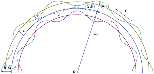
Let us assume the creeping transport through a curved passage with small solid particles. We have adopted curvilinear cylindrical coordinates in a three-dimensional curved passage where and rays are selected to be normal and parallel to the flow, respectively. Moreover, the surfaces of the container are supposed to be flexible and executing sinusoidal waves propagating at the lower and upper surfaces at a fixed pace “c.”
The boundary of the panel is expressed mathematically as
The symbols, like ã and , represent the radius of the channel and wave amplitude, accordingly. Moreover, is the wavelength, and executes time characteristics (see Figure 1). Here, we write the continuity and momentum conservation relations of the fluid and particle phases.
Fluid Phase
For fluid phase, the physical conservation laws of mass and momentum can be described in component form as
where C is the partial volume fraction parameter, μs is the solvent viscosity, and represent the fluid velocities, exhibits the stress tensor components whose general form is defined as [19]:
where ∂i Vi gives the gradient tensor of velocity vector, the dynamic viscosity is measured by μ, and flow constants are represented by β and l.
Particulate Phase
For particle phase, the above defined equation will take the following form:
In above relations, , and S represent the density of solid particles, their velocities and drag coefficient, respectively. The drag coefficient term and the empirical expression for the suspension viscosity are defined as [1]
Now suggesting the following lab and wave framework transformations
In new frame of reference, Equations (3), (4), (7), and (8) transformed into the subsequent form
Now we introduce the following dimensionless quantities for further simplification
Injecting the above revealed factors, Equations (10) through (13) become
Now inserting assumptions of long wavelength (δ ≈ 0) and low Reynolds number (Re ≈ 0), we arrive at
where the stress component τ12 for Eyring–Powell fluid is found as [19]
After proper substitution, Equation (22) becomes
We apply no-slip at the walls and the corresponding boundary conditions are manufactured as
In dimensionless form, using wave frame, we have
where dimensionless form of the channel height in wave frame is disclosed as ±h′ = ±(1 + φ cos x).
Methods and Results
This section has produced regular perturbation solutions for small values of A. So, we will use the following series expansion as a proposed solution for uf
The system generated by equating coefficients of exponent A0
with corresponding B.Cs
and the first order system (comparing coefficients of A1) is achieved as
with
After handling the above obtained problems by executing built-in commands of the computer software, Mathematica, we finally get the following results
Hence,
From Equation (21), we get the solution of particulate velocity, up, which is displayed below
Mathematical form of total mean volume flow rate due to fluid and particles is recognized as
where
and
Hence, we conclude
From the above described Equations (35) through (40), we can find the value of pressure gradient dp/dx, which is achieved as shown below:
Graphical Analysis
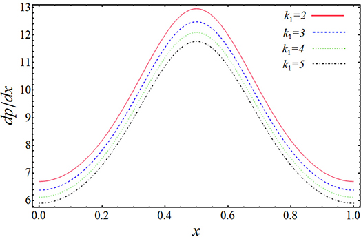
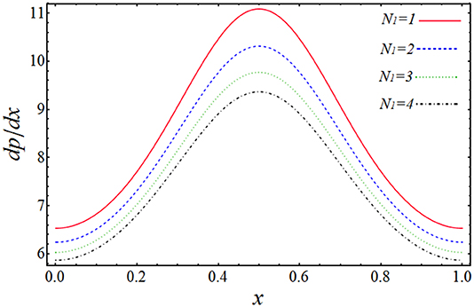
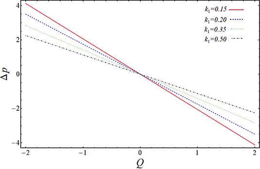
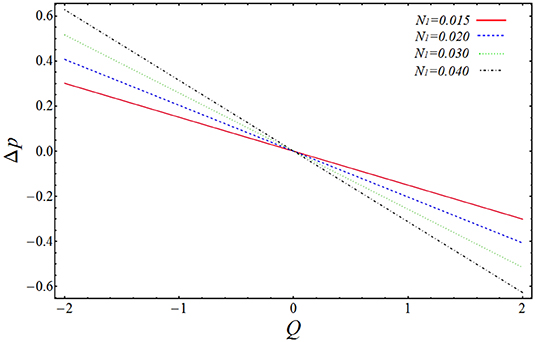
In the above section, we have solved the obtained governing equations for velocity, pressure gradient, and pressure rise by regular perturbation technique. The observing systems of differential equations have been handled on a mathematical software, Mathematica, via built-in DSolve commands. The more clarified results can be shown by plotting the graphs of above-obtained important quantities to see the effect of various physical parameters on them. The graphs will give a clearer picture of what is happening to the velocity, pressure gradient, and pressure rise when changes are made to the values of affecting parameters. To imagine these theoretical aspects, we have plotted the profiles of velocities uf and up against the radial coordinate y in Figures 2–5, the pressure gradient vs. the coordinate x in Figures 6, 7, and pressure rise along the flow rate Q in Figures 8, 9. The trapping bolus mechanism has been provoked in Figures 10, 11. It is observed from Figures 2, 3 that when we increase the numerical values of curvature parameter, k1, and solid particle concentration, N1, the fluid velocity, uf, is decreasing its height in most part of the channel for both the parameters expect the lower part where the velocity is showing almost a constant behavior with k1. They are usually included in systems that allow solids to settle to the bottom of the channel without any interruption. This is showing the physical fact that when channel is more curved and there are some solid particles placed in front of fluid flow, the velocity lowers, which is very much in agreement with the true experimental and physical facts. Figures 4, 5 are plotted for velocity of solid particles, up, with the variation of parameters k1 and N1. From these figures, it is captured that the velocity of solid particles, up, is showing almost a similar character as we have measured in the graphs of fluid velocity, uf, but the height of the parabolic path of velocity is less than that of fluid velocity, which admits that the velocity of particulate phase is less than that of the fluid phase. This is because the increase in curvature will slow down the particle's movement and because the large amount of particles will affect the motion and suppresses the fluid. Figures 6, 7 have been drawn to estimate the behavior of pressure gradient for different values of curvature parameter, k1 and N1. It is very obvious from these figures that pressure gradient profile is decreasing with the increasing magnitudes of both the parameters, and maximum change in axial pressure is depicted at the central part of the channel as compared to the both side corners. Figures 8, 9 shows the variation of pressure rise quantity, Δp, against the flow rate parameter, Q, to find the influence of k1 and N1. These two plots can be divided into two portions, namely Region-I (Δp > 0, η < 0) and Region-II (Δp < 0, η > 0), and we can observe that point of intersection of all the lines is almost, the origin. In Region-I, it can be seen that pressure rise curves are showing inverse behavior with the variation of k1, but in Region-II, the situation is completely opposite (see Figure 8). From Figure 9, it is quite clear that Δp rises proportionally to the increasing values of N1 in Region-I, while in Region-II, the curves are showing inverse relation.
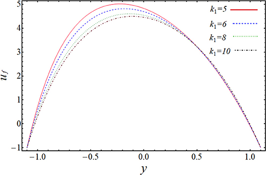
Figure 2. Change of velocity uf for k1 when Q = 1, x = 1, ϕ = 0.1, N1 = 0.9, B = 0.02, A = 0.01, C = 0.12.
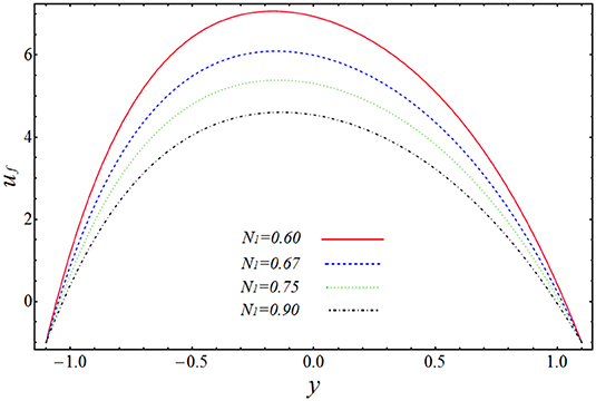
Figure 3. Change of velocity uf for N1 when Q = 1, x = 1, ϕ = 0.1, k1 = 8, B = 0.02, A = 0.01, C = 0.12.
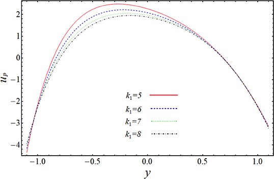
Figure 4. Change of velocity up for k1 when Q = 1, x = 1, ϕ = 0.1, N1 = 2, B = 0.02, A = 0.05, C = 0.01.
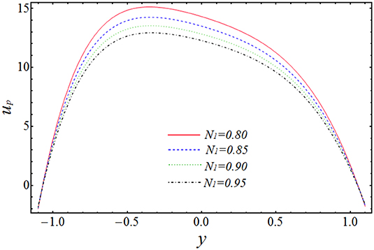
Figure 5. Change of velocity up for N1 when Q = 1, x = 1, ϕ = 0.1, k1 = 9, B = 0.02, A = 0.1, C = 0.9.

Figure 10. Trapping variation for fluid phase when N1 = 3, ϕ = 0.04, Q = 1, B = 0.1, A = 0.1, C = 0.03. (A) k = 3.1, (B) k = 3.2, and (C) k = 3.3.

Figure 11. Trapping variation for particulate phase when N1 = 3, ϕ = 0.04, Q = 1, B = 0.1, A = 0.1, C = 0.03. (A) k = 3.1, (B) k = 3.2, and (C) k = 3.3.
The most important phenomenon of peristaltic flows is circulating bolus trapping. The scenario is mentioned in Figures 10, 11. Figure 10 is developed for fluid phase under the variation of curvature parameter, k1. It is measured here that boluses expand against the increasing values of curvature, which shows that curvature affects the bolus shape directly. Figure 11 also depicts the same results for particulate phase streamlines, but, in this case, the number of boluses has been reduced to one.
Conclusions
In the above study, we have obtained the analytical solutions of peristaltic flow Eyring–Powell fluid model in a curved two-dimensional channel in the presence of solid particles. This study can contribute to the curing of diseases like urinary tract infections (UTIs). The problem is maintained simple under the implementation of lubrication approach. Analytical solutions have been achieved by applying the perturbation technique. The graphs have been plotted to show the behavior of some prominent quantities under the variation of pertinent parameters. From all of the above discussion, the following key points have been measured:
1. It is noted that both the curvature of the channel and the presence of solid particles slow the flow velocity, as compared with the flow in a straight channel and without solid particles.
2. It is observed that the curvature of the channel also affects the solid suspension velocity in the same manner as fluid velocity.
3. It is noticed that pressure gradient curves are getting lower as we increase the curvature of the channel and the amount of solid particles.
4. It is seen that the curvature of the channel decreases the peristaltic pressure on the negative side of the flow rate domain and increases on the other side.
5. It is examined from the above analysis that solid particles affect the pressure rise curves in quite the opposite manner when compared to the curvature parameter.
Data Availability Statement
The datasets generated for this study are available on request to the corresponding author.
Author Contributions
AR produced the methodology and formal analysis. MS wrote and edited the paper.
Funding
The authors wish to express their thanks for the financial support received from King Fahd University of Petroleum and Minerals, Saudi Arabia.
Conflict of Interest
The authors declare that the research was conducted in the absence of any commercial or financial relationships that could be construed as a potential conflict of interest.
Acknowledgments
The authors are grateful to the University of Education, Lahore Pakistan for providing suitable facilities to perform this research.
References
1. Bhatti MM, Zeeshan A, Tripathi D, Ellahi R. Thermally developed peristaltic propulsion of magnetic solid particles in biorheological fluids. Indian J Phys. (2018) 92:423–30. doi: 10.1007/s12648-017-1132-x
2. Hussain F, Ellahi R, Zeeshan A, Vafai K. Modelling study on heated couple stress fluid peristaltically conveying gold nanoparticles through coaxial tubes: a remedy for gland tumors and arthritis. J Mol Liq. (2018) 268:149–55. doi: 10.1016/j.molliq.2018.07.034
3. Riaz A, Alolaiyan H, Razaq A. Convective heat transfer and magnetohydrodynamics across a peristaltic channel coated with nonlinear nanofluid. Coatings. (2019) 9:816. doi: 10.3390/coatings9120816
4. Abbas MA, Bai YQ, Bhatti MM, Rashidi MM. Three dimensional peristaltic flow of hyperbolic tangent fluid in non-uniform channel having flexible walls. Alexandria Eng J. (2016) 55:653–62. doi: 10.1016/j.aej.2015.10.012
5. Akbar NS, Butt AW. Entropy generation analysis in convective ferromagnetic nano blood flow through a composite stenosed arteries with permeable wall. Commun Theor Phy. (2017) 67:554. doi: 10.1088/0253-6102/67/5/554
6. Enwald H, Peirano E, Almstedt AE. Eulerian two-phase flow theory applied to fluidization. Int J Multiph. (1996) 22:21–66. doi: 10.1016/S0301-9322(96)90004-X
7. Mekheimer KS, Kot ME. Suspension model for blood flow through arterial catheterization. Chem Eng Commun. (2010) 197:1195–214. doi: 10.1080/00986440903574883
8. Matousek P, Morris M. (Eds.). Emerging Raman Applications and Techniques in Biomedical and Pharmaceutical Fields. New York, NY: Springer Science & Business Media.
9. Beddow JK. Particle Characterization in Technology: Volume II: Morphological Analysis. Boca Raton, FL: CRC Press. (2018).
10. Yao J, Tao K, Huang Z. Flow of particulate-fluid suspension in a channel with porous walls. Transport Porous Med. (2013) 98:147–72. doi: 10.1007/s11242-013-0137-y
11. Mekheimer KS, Abd Elmaboud Y. Peristaltic transport of a particle–fluid suspension through a uniform and non-uniform annulus. Appl Bionics Biomech. (2008) 5:47–57. doi: 10.1080/11762320802376183
12. Kamel MH, Eldesoky IM, Maher BM, Abumandour RM. Slip effects on peristaltic transport of a particle-fluid suspension in a planar channel. Appl Bionics Biomech. (2015) 2015:703574. doi: 10.1155/2015/703574
13. Jiménez-Lozano J, Sen M. Corona, E. Analysis of peristaltic two-phase flow with application to ureteral biomechanics. Acta Mech. (2011) 219:91–109. doi: 10.1007/s00707-010-0438-y
14. Nadeem S, Maraj EN. The mathematical analysis for peristaltic flow of hyperbolic tangent fluid in a curved channel. Commun Theor Phy. (2013) 59:729. doi: 10.1088/0253-6102/59/6/14
15. Narla VK, Prasad KM, Ramanamurthy JV. Peristaltic transport of Jeffrey nanofluid in curved channels. Procedia Eng. (2015) 127:869–76. doi: 10.1016/j.proeng.2015.11.424
16. Weiss RM, Tamarkin FJ, Wheeler MA. Pacemaker activity in the upper urinary tract. J Smooth Muscle Res. (2006) 42:103–15. doi: 10.1540/jsmr.42.103
17. Lykoudis PS, Roos R. The fluid mechanics of the ureter from a lubrication theory point of view. J Fluid Mech. (1970) 43:661–74.
18. Griffiths DJ. Flow of urine through the ureter: a collapsible, muscular tube undergoing peristalsis. J Biomech Eng. (1989) 111:206–11.
Keywords: analytical solution, eyring-powell model, pumping phenomenon, solid particles, two-phase flow
Citation: Riaz A and Sadiq MA (2020) Particle–Fluid Suspension of a Non-Newtonian Fluid Through a Curved Passage: An Application of Urinary Tract Infections. Front. Phys. 8:109. doi: 10.3389/fphy.2020.00109
Received: 08 January 2020; Accepted: 23 March 2020;
Published: 06 May 2020.
Edited by:
Muhammad Mubashir Bhatti, Shanghai University, ChinaReviewed by:
Maryiam Javed, Institute of Space Technology, PakistanNoreen Akbar, National University of Sciences and Technology (NUST), Pakistan
Arash Asadollahi, Southern Illinois University Carbondale, United States
Anwar Shahid, Nanjing University of Aeronautics and Astronautics, China
Copyright © 2020 Riaz and Sadiq. This is an open-access article distributed under the terms of the Creative Commons Attribution License (CC BY). The use, distribution or reproduction in other forums is permitted, provided the original author(s) and the copyright owner(s) are credited and that the original publication in this journal is cited, in accordance with accepted academic practice. No use, distribution or reproduction is permitted which does not comply with these terms.
*Correspondence: Arshad Riaz, YXJzaGFkLXJpYXpAdWUuZWR1LnBr
 Arshad Riaz
 Muhammad Adil Sadiq