- 1Division MR Physics, Center for Medical Physics and Biomedical Engineering, Medical University of Vienna, Vienna, Austria
- 2Institute of Mechatronics and Computer Engineering, Technical University of Liberec, Liberec, Czechia
Purpose: The simulation optimization and implementation of a flexible 31P transmit/receive coil array, under the geometrical constraint of fitting into the housing of an already existing 12-channel proton array, to enable localized cardiac 31P MRS at 7 T is presented.
Methods: The performance in terms of homogeneity, power and SAR efficiency, and receive benchmark of 32 potential array designs was compared by full wave 3D electromagnetic simulation considering the respective optimal static shims. The design with the best performance was built and compared to a commercially available single loop in simulation and measurement.
Results: Simulation revealed an optimal array design comprising three overlapping elements, each sized 94 × 141 mm2. Simulation comparison with a single loop coil predicted a performance increase due to increased power efficiency and lower SAR values. This was verified by phantom measurements, where an SNR increase of 46% could be observed for localized 31P spectroscopy in a voxel positioned comparable to an in vivo cardiac measurement scenario.
Conclusion: A flexible 31P/1H RF coil array with improved SNR is presented, enabling localized in vivo cardiac 31P spectroscopy at 7 T.
Introduction
Phosphorus (31P) magnetic resonance spectroscopy (MRS) is known to be a powerful tool in the assessment of cell energy metabolism [1–3]. Coronary heart disease is one of the most common causes of death in the western hemisphere. A common reason for cardiac dysfunction is a deficit of the myocardial metabolism [4–6] for which cardiac 31P MRS is a direct and non-invasive assessment method [7–9]. The relative and absolute concentrations of ATP and PCr, and especially their ratio are strong indicators of cardiac dysfunction [10, 11]. The technique is very specific but suffers from inherently low sensitivity.
The low gyromagnetic ratio and in vivo concentration of 31P results in a low intrinsic signal to noise ratio (SNR) (31P-MRS has 100,000 × lower SNR than 1H MRI [12]), which leads to low spatial and temporal resolution. The nuclear magnetization increases proportionally with the main magnetic field strength (B-0) results in significant SNR increase for all nuclei detectable by MR. At ultra-high field (≥ 7 T) the proton (1H) homogeneity becomes more challenging in larger anatomic regions due to the short wavelength, however, this applies less strongly to 31P MRS because of the lower Larmor frequency. 31P cardiac MRS additionally benefits from increased B0 since the chemical-shift anisotropy helps to shorten the cardiac T1 relaxation times for at least PCr and ATP, therefore, increasing SNR [12]. Comparison of spectral quality between 3 T and 7 T cardiac 31P MRS, showed the significant benefit that comes with increasing B0, i.e., a 2.8 fold increase in PCr SNR [13].
To acquire as much of the theoretically available signal available, optimized RF coils need to be employed. The use of multiple receiving and/or transmitting elements in coil arrays offers SNR [1, 14] and/or acquisition speed advantages on the receive side [15, 16] and—if combined with adequate simulation and pulse design—greatly improved data quality and lower specific absorption rate on the transmit side [17, 18]. Electromagnetic coupling of the RF coil to the tissue and, therefore, SNR, increases when the coil is conformed to the anatomy [19]. Hence, most coils are assembled on anatomically form-fitted rigid housings. However, for applications where large anatomical inter-subject variability is expected, flexible RF coils are favorable to account for this heterogeneity in anatomy. Due to the longer wavelength for 31P it is still possible to use single loop coils for 7 T 31P MRS on the torso, which is the RF coil of choice in most published studies [13, 20, 21]. More elaborate designs include a 2-element Tx/Rx overlap array [9] and combinations of a Tx volume coil with Rx arrays [22–24].
The goal of this study was to design, build and evaluate a dedicated flexible 31P RF coil for phosphorus cardiac MR spectroscopy at 7 T to be integrated into a 12-channel transmission line resonator (TLR) array for torso MRI [25]. Due to the already existing coil housing, possible design dimensions for the 31P array were limited. Suitable designs with various element sizes and arrangements were investigated via 3D electromagnetic simulation in a comprehensive study. By definition of a performance measure that takes into account power efficiency, SAR efficiency, and homogeneity of the resulting transmit field , and the receive performance based on the resulting field, the best performing design was identified and eventually realized. A novel concept for floating dual-tuned cable traps working at both frequencies of operation (297.2 MHz for 1H and 120.3 MHz for 31P) was developed and integrated into the coil housings. The performance of the proposed array was compared with a commercially available standard single loop 31P RF coil for cardiac applications in simulation and measurement. Finally, the feasibility of acquiring localized 31P spectra in vitro was demonstrated.
Materials and Methods
RF Array Design
Potential RF coil designs were intended to cover the average human heart size of 12 × 8 × 6 cm3 and its location ~2 cm below the sternum [26]. The developed 31P array acts as an extension to an existing 1H RF coil [25], to enable acquisition of additional metabolic information of the heart muscle. The proton coil array consists of 12 TLR elements that were fabricated on a flexible substrate with a rigid PCB part in the center of each TLR element connected to their tuning and matching components. The PCB is connected to a rigid housing box incorporating each elements interface board, including T/R switches, 1:3 splitters and cable traps. The considered designs are to fit into the rigid housing boxes of the TLR elements, which poses a hard constraint on the maximum number of elements, coil sizes, and shapes. Figure 1 shows all considered RF coil array configurations, ranging from 1- to 4-channel arrays differing in size, arrangement and position, yielding a total number of 32 simulated array designs. The 12 TLR elements and their respective shields are depicted in gray. To discretely sample the possible configurations, the element size was varied in multiples of the 1H TLR element dimensions of 94 × 94 mm2. Regarding the position, the respective array center matches either the 1H array's center (corresponding to the center of the body) or is shifted by one half 1H element width to the patient's left. The flexibility of the 1H coil leads to a bending of the leftmost and rightmost elements. By shifting the center of the 31P coil the array experiences a different degree of bending which has an influence on the overall produced field. Those positions are denoted body-centered (bc) and heart-centered (hc), respectively.
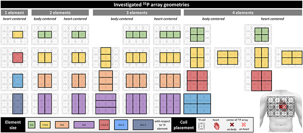
Figure 1. Simulated array designs. The designs are grouped by the number of channels, i.e., 1–4 elements. Each group is divided in body-centered (bc) and heart-centered (hc) arrays. bc-arrays are centered above the sternum, hc-arrays are shifted by half a housing box to the left, to be centered above the heart, as indicated on the torso on the bottom right. Colors represent the size of the individual elements, as stated in the legend on the bottom, the numbers are the element sizes in multiples of the underlying 12-ch 1H array housing boxes (grid on torso, bottom right); one unit cell has a length of 94 mm.
Electromagnetic Simulation
All coil designs were modeled in XFdtd 7.5 (Remcom, State College, PA, USA) using 1 mm thick wire as perfect conductors. The 3D EM simulations and their post-processing were computed on a workstation equipped with 4 GPUs (Tesla C2070, Nvidia, Santa Clara, CA, USA) enabling GPU acceleration, 12 CPUs (Intel® Xeon® X5690, 12 M Cache, 3.46 GHz, 6.40 GT/s Intel® QPI, Santa Clara, CA, USA), and 190 GB RAM. Each coil element was cut into equally long copper stubs connected by a capacitor to limit the electrical length of the coil. Depending on the configuration it was used in, the number of gaps was 8, 6, and 4 for the 1, 3, and 4 element arrays, respectively. This corresponds to stub-lengths between ≈ λ/15 and λ/42 for the 2 × 1.5 elements (4 channel array) and 1.5 × 1 element (1 element array), respectively, preventing any wavelength effects for all presented designs. All capacitors were eventually replaced by 50 Ω voltage sources to enable a fast RF co-simulation approach [27] in ADS (Keysight Technologies, Santa Rosa, CA, USA). All designs were simulated as overlap-decoupled arrays. An overlap factor of 0.86 was used [28]; as this factor only applies to quadratic elements, for non-quadratic elements decoupling was corrected by additional counter-wound inductances (CWI) [29] during RF co-simulation. Realistic loss incorporation was implemented by assigning capacitors their realistic equivalent series resistances by extrapolating an ESR model for the ATC 100 E capacitor series (http://www.atceramics.com/multilayer_capacitors.html). Solder joint losses were modeled as series resistances extrapolated to 120.3 MHz from literature [30]. Counter-wound inductances were modeled lossless since they were solely used to mimic sufficient overlap decoupling. Losses of the power splitter (−0.36 dB/channel) and the transmit/receive switches (−0.8 dB/channel) were measured on the bench and incorporated into the simulation.
The proposed array designs were loaded with realistic human body models (“Duke” and “Ella,” Virtual Family, IT'IS Foundation, Zurich, Switzerland), yielding a total of 64 3D simulation setups to be compared. Combination of 3D EM field data and co-simulation results and further post-processing was performed in Matlab 2017b (Mathworks, Natick, MA, USA). In order to compare the performance of the designs, optimal static shimming was obtained by varying the relative phase shift (Δφ) between the elements in 5° steps for the 2- and 3- element arrays and in 10° steps for the 4 element arrays, respectively (see Table 1 for the total number of phase sets |Φi|).
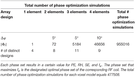
Table 1. The total number of phase sets for each of the four coil groups (1-, 2-, 3-, and 4-element arrays) as well as the total number of simulation setups are stated.
The optimal phases were determined for each design by maximizing a merit function fφ that is an equally weighted combination of power efficiency (PE), SAR efficiency (SE), and relative homogeneity (RH):
In Equation (1) the maximum value is evaluated over all simulated phase combinations for one specific design. The mean values were averaged over an ROI comprising the heart lumen and muscle and normalized with respect to the maximum value for the respective array. To identify the best design (di, i = 1,…, 32, i.e., all considered coil designs), an extended merit function ftot, additionally taking into account the receive efficiency in terms of SNR [31] was evaluated for all phase-optimized designs, but now normalized with respect to the maximum values for SE, PE, RH, and SNR over all investigated designs, respectively:
The values for PE, SE, RH, and SNR were averaged over “Duke” and “Ella,” both equipped with the same design.
To evaluate the influence of the CWI decoupling, another set of simulations with 2 elements of dimensions 1 × 1 ( 94 × 94 mm2) and 1 × 3 ( 94 × 282 mm2) and overlap factors between 0.76 to 0.92 in steps of 0.02 was performed. The arrays were loaded with a rectangular phantom filled with a material mimicking tissue (σ = 0.55 S/m, ε = 51) and were tuned, matched and decoupled in co-simulation using CWI where necessary. Static shimming for a spherical ROI with a diameter of 125 mm, located 35 mm below the RF coils was derived in the same manner as described in the previous paragraph using Equation (1). The arrays with the overlap factor resulting in best decoupling were compared to the corresponding arrays with overlap factor 0.86 with additional CWI in terms of S12, RH, PE, SE, SNR, and maximum 10 g-SAR. For a theoretical comparison of a commercially available single loop 31P coil (RAPID Biomedical GmbH, Rimpar, Germany) with the best design identified above, the performance of both RF coils was investigated using the aforementioned simulation workflow. The single loop has a diameter of 140 mm and an assumed wire thickness of 1.5 mm. The loss of the transmit/receive switch was set to the same as for the array (−0.8 dB) and incorporated in the evaluation. Both setups were positioned on the voxel models as closely to reality as possible in terms of distance and curvature in order to obtain results comparable to the measured data.
RF Coil Implementation
The design determined by simulation, i.e., the 3 channel 1 × 1.5 heart-centered array, was implemented. For flexibility, the 31P array was constructed out of flexible stranded wire (Ø = 2 mm). Crosstalk between the 1H and 31P arrays was minimized by replacing every second segmenting capacitor of the 31P loops by an LCC trap [32], resulting in three traps per element. To ease the handling of the whole coil and to keep it as flexible as possible, a separate interface box for the coil was avoided by placing transmit-receive switches, preamplifiers and power splitters inside the 12 separated 3D-printed housing boxes of the 1H array. Performance of the 31P array was tested on the bench, measuring S-parameters for five human volunteers (3 male, 2 female) using a vector network analyzer (E5071C, Agilent, Santa Clara, CA, USA).
In order to prevent common mode currents on the cables at both Larmor frequencies, double tuned floating cable traps were implemented [33]. By nesting two floating traps [34] into one another, blocking at two different frequencies can be achieved. Two hollow dielectric cylinders are split in half along their axes and are covered by conductive copper layers on the inside and outside walls. The inner trap shares its outer copper layer with the inner copper layer of the outer trap. At one end, all three concentric copper layers are short-circuited, while tuning capacitors are connecting the outer to the middle and the middle to the inner layer on the other side. The capacitors (CHB series, Exxelia Ceramics, Pessac, France) across the outer (inner) shell coarsely control the first (second) resonance frequency of the trap, respectively. By varying the distance between the two halves of the cylinders, the frequencies can be finely adjusted, however not independently. The trap body was 3D-printed (Rebel 2, Petr Zahradník Computer Laboratory, Ústí nad Labem, Czech Republic) from ABS plastic material (ε ≈ 2). The dimensions of the hollow cylinders were Ø = 8 mm, 13 mm, and 20 mm, respectively, all with a length of 55 mm.
MR Measurements
All MR measurements were conducted on a 7 T whole body MR scanner (Siemens Magnetom, Erlangen, Germany), using a tissue mimicking torso phantom with dimensions of 230 × 280 × 380 mm3 containing saline solution (σ ≈ 0.5 S/m, ε ≈ 80) with 1.57 g/L K2HPO4 and 0.14 g/L KH2PO4 (0.01 M/l PO4, pH = 8). The coil was positioned centrically with respect to the phantom which was located in the isocenter of the scanner.
31P CSI data was acquired using an ultrashort TE chemical shift imaging (ute-CSI) sequence [35] (TR/TE = 1770/2.3 ms, FOV 400 × 400 × 350 mm3, matrix size 8 × 16 × 8, vector size 512, scan time 7:46 min). For localized 31P spectroscopy a stimulated echo acquisition mode (STEAM) sequence [36] was applied (TR/TE = 3,000/13.4 ms, TM = 6.9 ms, voxel size 50 × 20 × 50 mm3, vector size 1024, 32 averages, voxel location 7 cm from phantom wall, scan time 1:36 min). All spectra were post-processed using the MATLAB-based OXford Spectroscopy Analysis (OXSA) toolbox [37] and its implementation of the AMARES fitting method [38]. For combination of the three individual channels of the array a whitened singular value decomposition (WSVD) approach was used [39].
LCC trap performance was validated inside the scanner, by acquiring flip angle maps in an equally sized phantom containing only saline solution (σ ≈ 0.5 S/m, ε ≈ 80) with and without the 31P array integrated into the 1H coil housings using a saturated Turbo FLASH (satTFL) sequence [40] (TR/TE = 10,000/2.02 ms, FOV = 450 × 450 mm2, matrix size 128 × 128, rectangular slice-selective saturation pulse, pulse duration 700 ms, reference voltage 300 V, slice thickness 10 mm).
Results
RF Array Design
The computational cost of each individual full wave simulation depends on the size of the array, the number of gaps, and the voxel model used as load. CPU/GPU RAM requirements and the total computation time for a single EMS were between 0.38/0.25 GB and 1.47 h (design: Ella 1 element 1.5 × 1 hc) and 2.49/1.52 GB and 49.9 h (design: Duke four element 2 × 1.5 bc). Post-processing of the individual designs is highly dependent on the number of channels, ergo the number of different phase sets that need to be calculated in order to evaluate the static shimming, and was between 0.46 and 13.6 min for the Ella 1 element 1.5 × 1 hc and Duke 4 element 2 × 1.5 bc, respectively.
Static shimming was optimized for each of the 64 simulated designs (32 for “Duke,” and 32 for “Ella”). Figure 2A shows the resulting point cloud for the shimming procedure for an exemplary dataset. Each point represents the result in terms of RH, PE, and SE for a certain phase set. The phase sets that result in maximum RH, PE, SE, and fφ, are marked by blue, black, green, and red circles, respectively. Figure 2B shows the resulting maps achieved with the optimal phase set for best RH, best PE, and best SE (which is equal to best fφ in the shown case). Evaluating the extended merit function ftot over all designs resulted in the final design choice of a 3 element array with element sizes of 94 × 141 mm2, centered above the heart. Figure 3 depicts the mean values over the heart ROI for ftot, RH, SE, PE, and SNR for all simulated designs for Ella, Duke, and the average over both (black).
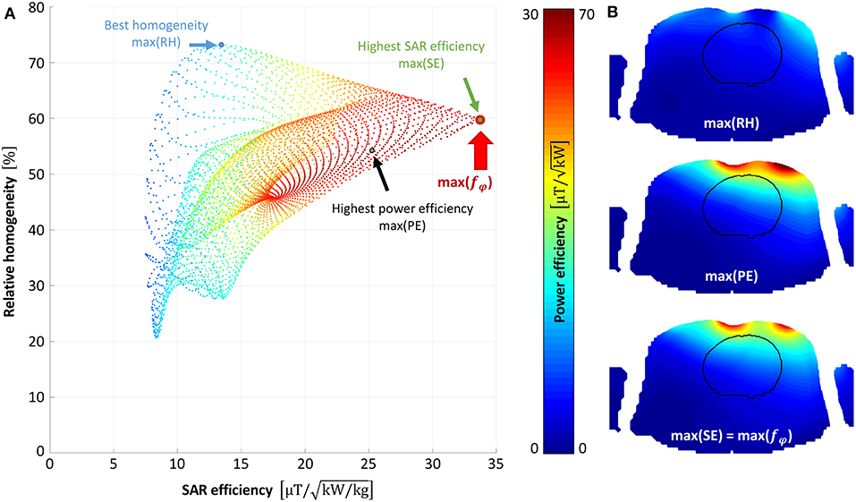
Figure 2. Static shimming result. Static shimming result for the best-performing design (3-element heart centered with 94 × 141 mm2 elements) simulated on Duke is shown. (A) depicts the resulting point cloud (5,184 points), where each point represents the array's performance in terms of relative homogeneity (RH), power efficiency (PE), and SAR efficiency (SE), for a certain phase set. The optimal phase set is chosen where the merit function fφ is maximized (depicted as a red circle). In (B) the resulting /√Pin maps are shown for the phase shifts that maximize RH, PE, SE and f, respectively.
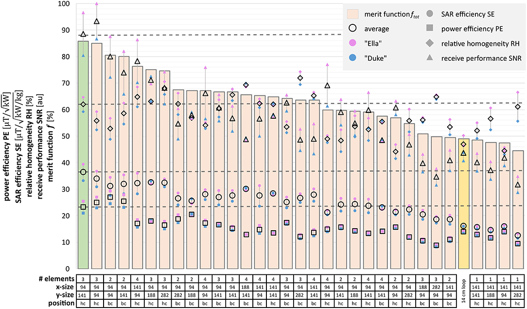
Figure 3. Comparison of the 32 simulated RF coil designs. The performance parameters relative homogeneity (RH, diamonds), power efficiency (PE, squares), SAR efficiency (SE, circles), and receive efficiency (SNR, triangles) are plotted for each design. Results for Ella, Duke, and their average are depicted in purple, blue, and transparent with black rim, respectively. The figure of merit f tot is displayed as bars. The highlighted bar indicates the performance parameters of the reference single loop coil. Below the chart, the table summarizes the geometric properties of each array, x- and y-size are given in multiples of 94 mm, the unit size of the housing boxes of the underlying 1H array. The best design for both Duke and Ella is the 3-element heart-centered array with 94 × 141 mm2.
In the 2-channel array simulation for determining the influence of the CWI decoupling, the optimal overlap factor was determined to be 0.88 for the 1 × 1 and 0.78 for the 1 × 3 sized arrays. S21 for optimized overlap decoupling (OL) only and fixed overlap plus additional CWI decoupling (OL + CWI) were always below −17.1 db. For both array types, i.e., 1 × 1 and 1 × 3, the highest deviation between OL + CW and OL designs was found in the maximum 10 g SAR value, with an increase of 1.29% ( 0.02 1/kg) and 4.13 % ( 0.03 1/kg) for the 1 × 1 and 1 × 3 arrays, respectively. All results are summarized in Table 2. These findings support the hypothesis that simplifying the simulations of all array designs with a fixed overlap + CWI to mimic optimal overlap decoupling is reasonable.
Bench measurements of the implemented array in loaded condition before and after incorporation into the 1H housing were conducted on 5 human volunteers (3 male, 2 female, 30 ± 3.6 years) and show sufficient matching and isolation between array elements, i.e., the reflection coefficients (S11, S22, S33) were always below −17.5 dB and −17.2 dB, respectively, while transmission coefficients (S12, S23, S31) were below −13.1 and −13.6 dB. The array needed to be slightly retuned and rematched after integration due to slight position changes and distance to the sample. The measured Q ratio (Qu/Ql) for all three elements prior and after incorporation was above 5.5 and 5.7, indicating sample loss dominance and negligible additional losses due to the 1H coil and housing. The floating double tuned traps were correctly tuned, with a blocking of −10.5 dB/−34 dB and a bandwidth of 3 MHz/6 MHz at 120 MHz/297.2 MHz respectively. The tuning range for both blocking frequencies by changing the gap size between the half-cylinders was ±10%, which was sufficient to tune the traps to the desired frequencies.
Performance Comparison With Single Loop
In simulation the proposed three element array yields a mean power efficiency in the heart ROI that is 58% higher than the respective values for the single loop reference coil. In terms of SAR efficiency, the array performs 124% better than the loop; the 10 g averaged SAR values decrease by 51%. Relative homogeneity is 30% better. The results are presented in detail in Table 3 and Figure 4.
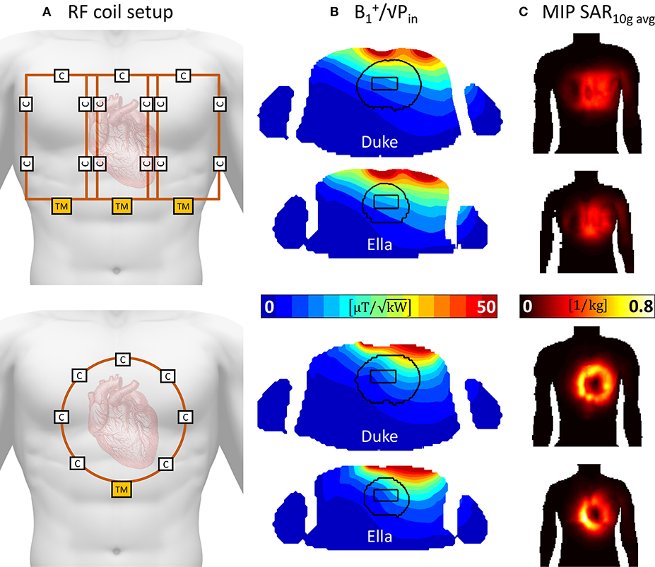
Figure 4. Simulation comparison of the proposed 3-element array with a standard 14 cm single loop coil. (A) depicts the RF coil setups, the proposed array is depicted in the top row, whereas the single loop is depicted in the bottom part. Both coils are positioned centered over the heart. (B) shows the resulting /√Pin maps in a transversal slice through the center of the heart ROI. Higher values are seen for the 3-element arrays. (C) depicts coronal maximum intensity projections of the 10 g averaged specific absorption rate (SAR).
MR Measurements
A maximum deviation in acquired with and without the 31P array present of <20% was found (see Figure 5). Before acquiring CSI data, a series of localized spectra were obtained in order to find the reference voltage for a voxel in a location similar to the human heart, i.e., 7 cm from phantom surface wall in y-direction. Figure 6A shows all spectra plotted as signal amplitude vs. reference voltage. The reference voltage is the voltage that would be required to achieve a 90° flip angle using a 1 ms block pulse. The signal amplitudes were fitted with a sin3 function, corresponding to the signal equation for STEAM sequences. The reference voltage for the single loop is 400 V, whereas the array needs 880 V in the same voxel. The localized spectra of the acquisitions where 90° were reached are shown in Figure 6B for the array and the single loop. From these spectra SNR values of 52 for the array, and 35 for the single loop were calculated. In Figures 6C,D transversal and sagittal metabolic maps acquired with the array (top) and the single loop (bottom) are displayed.
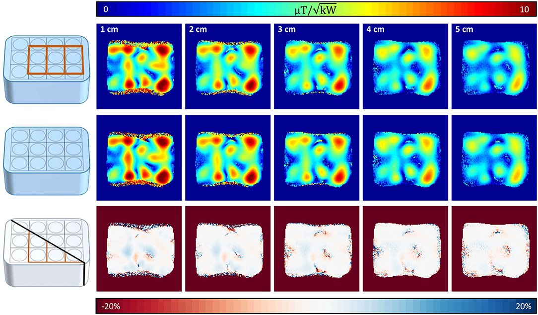
Figure 5. Coronal 1H maps with and without 31P array present. Top row shows coronal slices (10 mm slice thickness, distance from surface/RF coil 1–5 cm) with the 31P array positioned below the proton array, whereas in the middle row the same slices are shown without the 31P array present. Bottom row shows the resulting difference of the maps above. Highest deviations are encountered where the mapping sequence produced artifacts due to the high of surface coils.
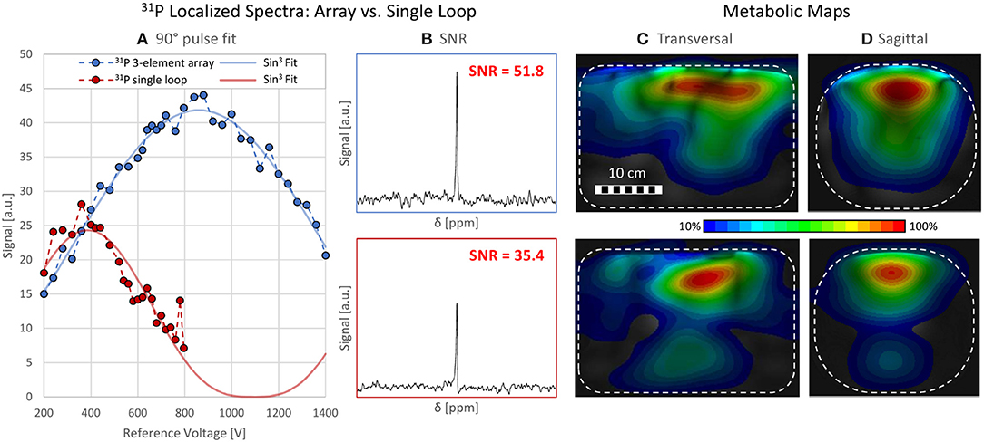
Figure 6. Localized Spectroscopy and CSI data. (A) shows all data points acquired with a STEAM sequence from a voxel of size 50 × 20 × 50 mm3 7 cm within a torso phantom containing 31P. The blue and red data points represent the spectra acquired with the array and the loop, respectively. The course of the signal amplitude is fitted with a sin3 function corresponding to the signal equation for STEAM sequences. The reference voltages are 400 V (single loop) and 880 V (array). (B) SNR comparison of localized spectra for array (SNR = 51.8, top) and the loop (SNR = 35.4, bottom). (C,D) Metabolic maps, interpolated from CSI data, scaled to their individual maximum, in a (C) transversal and (D) sagittal slice for the array (top) and the single loop (bottom). The phantom is depicted as a white rectangle.
Discussion
In this work we show the successful integration of an optimized 3-channel 31P array for cardiac MRS at 7 T into a flexible 12 channel 1H coil.
A set of 32 31P array layouts, each evaluated using two different voxel models (one male, one female) to incorporate inter-subject variability was compared via full wave 3D electromagnetic simulation with realistic loss estimations to find the best performing array design. Static shim phase sets optimized for a combination of homogeneity, power and SAR efficiency were calculated for all investigated arrays.
All array layouts used a fixed overlap and additional counter-wound inductances to decouple the array elements in order to save simulation time, since finding the optimal overlap for differently sized array elements is very time consuming due to the necessity to rerun the 3D simulation for each setup multiple times while changing the overlap factor slightly, until optimal decoupling is achieved. It was exemplarily shown for two elements that the differences between optimal overlap only as compared to a fixed overlap factor and the additional CWIs are negligible.
A new way of visualizing shimming results in the entire phase shift parameter space was introduced, allowing for quick and easy visual inspection of the variation of performance parameters on the chosen phase set. A figure of merit taking into account an equally weighted combination of homogeneity, power and SAR efficiency was employed. This approach can be universally employed for any transmit array. Depending on the requirements of the application, the weights for the figure of merit could be changed to favor a specific performance parameter. This could be useful e.g., to optimize the shim more strongly for SAR efficiency in applications that are SAR demanding, or for homogeneity where a uniform flip angle distribution is essential, or for power efficiency where the available transmit power is limiting.
The best performing design was a 3-element array centered above the heart with individual elements of 94 × 141 mm2. It was integrated into the housings of the proton coil, including performance tests on the bench and in the MR scanner.
Maximum deviations for the 1H array alone vs. the combination with the 31P array were found in superficial areas and were below 20%, indicating sufficient decoupling between the two frequencies.
Simulation predicted that the proposed 3-element RF array would outperform a 14 cm single loop coil for cardiac MRS at 7 T in terms of power efficiency (+ 58% over the whole heart, + 27% in the measured VOI), SAR efficiency (+124% heart, + 81% VOI), and relative homogeneity (+30% heart, +13% VOI).
Despite the higher calculated power efficiency, in the experiment higher pulse amplitudes were necessary in the VOI for the array when compared to the single loop (Figure 6A). The main cause for this behavior is that the array was simulated and constructed to be optimal for human subjects, but the measurement was performed on a homogeneous phantom. Firstly, this led to a mismatch of the RF coil to the phantom load, resulting in a significant decrease of the effective input voltage at the coil ports. Secondly, the power efficiency was simulated for the array bent on a human load, but since the phantom did not allow for bending, the coil was used in flat configuration, leading to lower efficiency in depth. In addition, shielding effects from the conductive structures of the 1H coil elements and interfaces were not considered in simulation and could possibly also reduce transmit efficiency. Losses associated to imperfect decoupling from the 1H array, and induced common mode currents on the cable shields further contribute to the difference, although to a lesser extent, since an effort was made to keep them as small as possible.
Nevertheless, an SNR increase of + 46% in the VOI was demonstrated with identical flip angle as in the reference coil, which shows the advantages of the array in terms of receive sensitivity and supports the above reasoning for suboptimal transmit performance on the phantom.
Because of the mentioned limitations of the phantom measurement, an even stronger increase for in vivo measurements can be expected. In a next step, the required tests and documentation of the coil for approval of the ethics board will be established to enable the usage of the coil in an in vivo study.
Data Availability Statement
The datasets generated for this study are available on request to the corresponding author.
Author Contributions
SR and EL designed the study. SR did the 3D simulations and drafted the manuscript. SR and MV implemented and measured the coil on the bench. SR, SW, and AS did the MR measurements and the post-processing. EL, SW, and AS revised the manuscript.
Funding
This work was funded by the Austrian Science Fund (FWF) grants P28059-N36 and P28867-B30.
Conflict of Interest
The authors declare that the research was conducted in the absence of any commercial or financial relationships that could be construed as a potential conflict of interest.
References
1. Roemer PB, Edelstein WA, Hayes CE, Souza SP, Mueller OM. The NMR phased array. Magn Reson Med. (1990) 16:192–225. doi: 10.1002/mrm.1910160203
2. Buchli R, Meier D, Martin E, Boesiger P. Assessment of absolute metabolite concentrations in human tissue by 31P MRS in vivo. Part II: Muscle, liver, kidney. Magn Reson Med. (1994) 32:453–8. doi: 10.1002/mrm.1910320405
3. Lee J-H, Komoroski RA, Chu W-J, Dudley JA. Methods and applications of phosphorus nmr spectroscopy in vivo. Ann Rep NMR Spectr. (2012) 75:115–60. doi: 10.1016/B978-0-12-397018-3.00003-X
4. Bottomley PA, Wu KC, Gerstenblith G, Schulman SP, Steinberg A, Weiss RG. Reduced myocardial creatine kinase flux in human myocardial infarction an in vivo phosphorus magnetic resonance spectroscopy study. Circulation. (2009) 119:1918–24. doi: 10.1161/CIRCULATIONAHA.108.823187
5. Yabe T, Mitsunami K, Inubushi T, Kinoshita M. Quantitative measurements of cardiac phosphorus metabolites in coronary artery disease by 31 p magnetic resonance spectroscopy. Circulation. (1995) 92:15–23. doi: 10.1161/01.CIR.92.1.15
6. Neubauer S, Krahe T, Schindler R, Horn M, Hillenbrand H, Entzeroth C, et al. 31P magnetic resonance spectroscopy in dilated cardiomyopathy and coronary artery disease. Altered cardiac high-energy phosphate metabolism in heart failure. Circulation. (1992) 86:1810–8. doi: 10.1161/01.CIR.86.6.1810
7. Bottomley P. Noninvasive study of high-energy phosphate metabolism in human heart by depth-resolved 31P NMR spectroscopy. Science. (1985) 229:769–72. doi: 10.1126/science.4023711
8. Bottomley PA. NMR spectroscopy of the human heart. In: Harris RK, Wasylishen RL, editors. eMagRes. Chichester: John Wiley & Sons, Ltd. (2009). p. 1–20. doi: 10.1002/9780470034590.emrstm0345.pub2
9. Valkovič L, Clarke WT, Schmid AI, Raman B, Ellis J, Watkins H, et al. Measuring inorganic phosphate and intracellular pH in the healthy and hypertrophic cardiomyopathy hearts by in vivo 7T 31P-cardiovascular magnetic resonance spectroscopy. J Cardiovasc Magn Reson. (2019) 21:19. doi: 10.1186/s12968-019-0529-4
10. Neubauer S, Horn M, Cramer M, Harre K, Newell JB, Peters W, et al. Myocardial Phosphocreatine-to-ATP ratio is a predictor of mortality in patients with dilated cardiomyopathy. Circulation. (1997) 96:2190–6. doi: 10.1161/01.CIR.96.7.2190
11. Neubauer S. The failing heart — an engine out of fuel. N Engl J Med. (2007) 356:1140–51. doi: 10.1056/NEJMra063052
12. Ladd ME, Bachert P, Meyerspeer M, Moser E, Nagel AM, Norris DG, et al. Pros and cons of ultra-high-field MRI/MRS for human application. Prog Nucl Magn Reson Spectrosc. (2018) 109:1–50. doi: 10.1016/j.pnmrs.2018.06.001
13. Rodgers CT, Clarke WT, Snyder C, Vaughan JT, Neubauer S, Robson MD. Human cardiac 31P magnetic resonance spectroscopy at 7 tesla. Magn Reson Med. (2014) 72:304–15. doi: 10.1002/mrm.24922
14. Hardy CJ, Bottomley PA, Rohling KW, Roemer PB. An NMR phased array for human cardiac 31P spectroscopy. Magn Reson Med. (1992) 28:54–64. doi: 10.1002/mrm.1910280106
15. Pruessmann KP, Weiger M, Scheidegger MB, Boesiger P. SENSE: sensitivity encoding for fast MRI. Magn Reson Med. (1999) 42:952–62. doi: 10.1002/(SICI)1522-2594(199911)42:5<952::AID-MRM16>3.0.CO;2-S
16. Keil B, Wald LL. Massively parallel MRI detector arrays. J Magn Reson. (2013) 229:75–89. doi: 10.1016/j.jmr.2013.02.001
17. Katscher U, Börnert P, Leussler C, van den Brink JS. Transmit SENSE. Magn Reson Med. (2003) 49:144–50. doi: 10.1002/mrm.10353
18. Ullmann P, Junge S, Wick M, Seifert F, Ruhm W, Hennig J. Experimental analysis of parallel excitation using dedicated coil setups and simultaneous RF transmission on multiple channels. Magn Reson Med. (2005) 54:994–1001. doi: 10.1002/mrm.20646
19. Goluch S, Kuehne A, Meyerspeer M, Kriegl R, Schmid AI, Fiedler GB, et al. A form-fitted three channel 31P, two channel 1H transceiver coil array for calf muscle studies at 7 T. Magn Reson Med. (2015) 73:2376–89. doi: 10.1002/mrm.25339
20. Chmelik M, Považan M, Krššák M, Gruber S, Tkačov M, Trattnig S, et al. In vivo 31 P magnetic resonance spectroscopy of the human liver at 7 T: an initial experience. NMR Biomed. (2014) 27:478–85. doi: 10.1002/nbm.3084
21. Ellis J, Valkovič L, Purvis LAB, Clarke WT, Rodgers CT. Reproducibility of human cardiac phosphorus MRS (31P-MRS) at 7 T. NMR Biomed. (2019) 32:e4095. doi: 10.1002/nbm.4095
22. Löring J, van der Kemp WJM, Almujayyaz S, van Oorschot JWM, Luijten PR, Klomp DWJ. Whole-body radiofrequency coil for 31P MRSI at 7T. NMR Biomed. (2016) 29:709–20. doi: 10.1002/nbm.3517
23. Valkovič L, Dragonu I, Almujayyaz S, Batzakis A, Young LAJ, Purvis LAB, et al. Using a whole-body 31P birdcage transmit coil and 16-element receive array for human cardiac metabolic imaging at 7T Lundberg P, editor. PLoS ONE. (2017) 12:e0187153. doi: 10.1371/journal.pone.0187153
24. Purvis LAB, Clarke WT, Valkovič L, Levick C, Pavlides M, Barnes E, et al. Phosphodiester content measured in human liver by in vivo 31P MR spectroscopy at 7 tesla. Magn Reson Med. (2017) 78:2095–105. doi: 10.1002/mrm.26635
25. Hosseinnezhadian S, Frass-Kriegl R, Goluch-Roat S, Pichler M, Sieg J, Vít M, et al. A flexible 12-channel transceiver array of transmission line resonators for 7 T MRI. J Magn Reson. (2018) 296:47–59. doi: 10.1016/j.jmr.2018.08.013
26. Betts JG, Desaix P, Johnson EW, Johnson JE, Korol O, Kruse D, et al. Anatomy and Physiology. Houston, TX : OpenStax College, Rice University. (2017).
27. Kozlov M, Turner R. Analysis of RF transmit performance for a 7T dual row multichannel MRI loop array. Conf Proc IEEE Eng Med Biol Soc. (2011) 2011:547–53. doi: 10.1109/IEMBS.2011.6090101
28. Mispelter J, Lupu M, Briguet A. Nmr Probeheads for Biophysical and Biomedical Experiments: Theoretical Principles and Practical Guidelines. 1st ed. London: Imperial College Press. (2006). doi: 10.1142/p438
29. Lee RF, Giaquinto RO, Hardy CJ. Coupling and decoupling theory and its application to the MRI phased array. Magn Reson Med. (2002) 48:203–13. doi: 10.1002/mrm.10186
30. Kumar A, Edelstein WA, Bottomley PA. Noise figure limits for circular loop MR coils. Magn Reson Med. (2009) 61:1201–9. doi: 10.1002/mrm.21948
31. Wright SM, Wald LL. Theory and application of array coils in MR spectroscopy. NMR Biomed. (1997) 10:394–410. doi: 10.1002/(SICI)1099-1492(199712)10:8<394::AID-NBM494>3.0.CO;2-0
32. Meyerspeer M, Serés Roig E, Gruetter R, Magill AW. An improved trap design for decoupling multinuclear RF coils. Magn Reson Med. (2014) 72:584–90. doi: 10.1002/mrm.24931
33. Wilcox M, McDougall M. Double-Tuned cable traps for multinuclear MRI And MRS. In: 2018 40th Annual International Conference of the IEEE Engineering in Medicine and Biology Society (EMBC). Honolulu, HI (2018). p. 1364–7. doi: 10.1109/EMBC.2018.8512474
34. Seeber DA, Jevtic J, Menon A. Floating shield current suppression trap. Concepts Magn Reson. (2004) 21B:26–31. doi: 10.1002/cmr.b.20008
35. Robson MD, Tyler DJ, Neubauer S. Ultrashort TE chemical shift imaging (UTE-CSI). Magn Reson Med. (2005) 53:267–74. doi: 10.1002/mrm.20344
36. Frahm J, Merboldt KD, Hänicke W. Localized proton spectroscopy using stimulated echoes. J Magn Reson. (1987) 72:502–8. doi: 10.1016/0022-2364(87)90154-5
37. Purvis LAB, Clarke WT, Biasiolli L, Valkovič L, Robson MD, Rodgers CT. OXSA: an open-source magnetic resonance spectroscopy analysis toolbox in MATLAB Motta A, editor. PLoS ONE. (2017) 12:e0185356. doi: 10.1371/journal.pone.0185356
38. Vanhamme L, van den Boogaart A, Van Huffel S. Improved method for accurate and efficient quantification of MRS data with use of prior knowledge. J Magn Reson. (1997) 129:35–43. doi: 10.1006/jmre.1997.1244
39. Rodgers CT, Robson MD. Receive array magnetic resonance spectroscopy: whitened singular value decomposition (WSVD) gives optimal bayesian solution. Magn Reson Med. (2010) 63:881–91. doi: 10.1002/mrm.22230
Keywords: 31P cardiac MRS, 3D EM simulation, RF coil design, X-nucleus, ultra-high field
Citation: Roat S, Vít M, Wampl S, Schmid AI and Laistler E (2020) A Flexible Array for Cardiac 31P MR Spectroscopy at 7 T. Front. Phys. 8:92. doi: 10.3389/fphy.2020.00092
Received: 29 November 2019; Accepted: 12 March 2020;
Published: 15 April 2020.
Edited by:
Zhen Cheng, Stanford University, United StatesReviewed by:
Angelo Galante, University of L'Aquila, ItalyMichael D. Noseworthy, McMaster University, Canada
Copyright © 2020 Roat, Vít, Wampl, Schmid and Laistler. This is an open-access article distributed under the terms of the Creative Commons Attribution License (CC BY). The use, distribution or reproduction in other forums is permitted, provided the original author(s) and the copyright owner(s) are credited and that the original publication in this journal is cited, in accordance with accepted academic practice. No use, distribution or reproduction is permitted which does not comply with these terms.
*Correspondence: Elmar Laistler, ZWxtYXIubGFpc3RsZXJAbWVkdW5pd2llbi5hYy5hdA==
 Sigrun Roat
 Martin Vít2
 Albrecht Ingo Schmid
 Elmar Laistler
