 Scott J. Doyle
 Alex Bennet
 Dimitrios Tsifakis
 James P. Dedrick1
 Rod W. Boswell
 Christine Charles
94% of researchers rate our articles as excellent or good
Learn more about the work of our research integrity team to safeguard the quality of each article we publish.
Find out more
ORIGINAL RESEARCH article
Front. Phys., 18 February 2020
Sec. Low-Temperature Plasma Physics
Volume 8 - 2020 | https://doi.org/10.3389/fphy.2020.00024
This article is part of the Research Topic2021 Frontiers in Physics Editor's pickView all 20 articles
The study and control of resonant instabilities in magnetized plasmas is of fundamental interest over a wide range of applications from industrially relevant plasmas to plasma sources for spacecraft propulsion. In this work electrostatic probes were employed to measure a 4–20 kHz instability in the ion saturation current downstream of an electric double layer (DL) in an expanding helicon plasma source. The amplitude and frequency of the instability were found to vary in inverse proportion to the operating argon gas pressure (0.2–0.6 mTorr) and in direct proportion to the applied rf power (100–600 W) and applied solenoid current (3–8 A). A spatially resolved characterization of the maximum instability amplitude determined two radial maxima, corresponding to the locations of most positive radial ion density gradient. Control and inhibition of the instability were achieved through the application of a kHz voltage amplitude modulation to the 13.56 MHz radio-frequency (rf) power supplied to the helicon antenna. Through the application of voltage amplitude modulations in the frequency range 2–12 kHz the instability was reduced by up to 65%, exhibiting a greater reduction at higher applied modulation frequencies. This effect is described through a variation in the radial ion density gradient via asymmetrically attenuated ion acoustic density perturbations induced by the applied voltage modulation. The application of voltage amplitude modulations has been demonstrated as a potential control mechanism for density gradient driven instabilities in magnetized plasmas.
Electromagnetic propulsion devices present a growing alternative to chemical propulsion sources as they are capable of providing higher specific impulses and employ less volatile propellants [1–4]. Within this catagory, radio-frequency (rf), electrodeless plasma thrusters are of particular interest as they could provide extended operational lifetimes as compared to more commonly employed Hall and gridded ion thrusters. The Helicon Double Layer Thruster (HDLT) is an example of a rf, electrodeless, neutraliser-free plasma thruster and employs a current-free double layer (CFDL) to accelerate an ion beam to velocities beyond the local ion sound speed, producing variable thrust in the mN range [5–9].
Over the last two decades, a number of expanding plasma devices have been used to explore the physics of low pressure plasmas flowing through diverging magnetic nozzles for conditions relevant to HDLT-type thrusters. These devices typically consist of a rf plasma source surrounded by a set of solenoids and contiguously attached to a larger radius expansion chamber. Much of the previous work conducted in these devices has focused on characterizing the axial DL [9–13] and subsequent ion beam [14–16] as well as a region of high density plasma located off-axis in the expansion chamber known as the high-density conics [17–22]. The conics are ionized locally by hot electron populations, which stream along the most radial magnetic field lines to escape the source region, and result in a hollow radial plasma density profile in the expansion region. The downstream region of these expanding plasma devices can therefore be described by an axial supersonic ion beam radially surrounded by the stationary high density conics.
Strong gradients in magnetic field strength, plasma potential, density, and electron temperature are inherent to the expanding plasma devices in which DLs, ion beams and conics have been observed [23, 24]. Ion acoustic instabilities generated by strong gradients in these plasma properties have been the subject of investigation for many years [25–28], and extensive work has been preformed on density gradient driven, kHz range, drift wave instabilities in helicon sources [29–34] and turbulent or anomalous transport in other types of electric propulsion devices, e.g., spoke instabilities in Hall thrusters [35–37].
In an experimental study on the HDLT, Aanesland et al. showed the presence of a 10–20 kHz upstream ionization instability in the source region of the Chi Kung reactor at the Australian National University (ANU) and investigated its source [38, 39]. The authors of that study theorized that the instability was an ionization instability caused by an energetic electron population accelerated into the plasma source from the expansion region by the CFDL. However, measurements of the axial upstream Electron energy probability function (EEPF) taken by Takahashi et al. in the same reactor did not show the presence of an accelerated electron beam in the source region [40]. The source of the instability presented in the previous work is yet to be fully understood and further investigation is necessary to understand the particle dynamics in these expanding plasma devices.
In this work, an instability found at similar frequencies to that presented in the previous work by Aanesland et al. is detected in the downstream region of the Chi Kung reactor. Control of the instability is achieved via the application of variable frequency voltage amplitude modulations to the rf power supplied to the rf antenna surrounding the source region. Here, ion acoustic waves, i.e., ion density perturbations, are employed to control and reduce the instability via modification of the radial ion density gradient. An overview of the Chi-Kung reactor and the electrostatic diagnostics employed is given in section 2. The instability amplitude and frequency are spatially characterized in section 3, revealing the apparent source of the instability and the dependence on operating pressure, applied rf antenna power and solenoid current. The voltage amplitude modulation technique is detailed in section 4.1 and control of the instability is demonstrated for varying voltage amplitude modulation frequencies in section 4.2 including a mathematical description of the proposed control mechanism.
The measurements presented in this study were taken in the Chi-Kung helicon plasma reactor, shown in Figure 1. The operation of Chi Kung is described in detail in Charles and Boswell [8] and is briefly outlined here for completeness. The Chi Kung plasma reactor source chamber consists of a 31 cm long, 0.65 cm thick, 13.7 cm inner diameter cylindrical Pyrex tube, contiguously connected to a 30 cm long, 32 cm inner diameter grounded aluminum expansion chamber. The axial coordinate system Z is zeroed at the interface between the source chamber and the expansion region, as shown in Figure 1. To compare with previous measurements of the instability in Aanesland et al. [39], an insulating glass plate is positioned on the upstream side of the source chamber, illustrated in Figure 1 by a light blue section at Z = −31 cm. The presence of an insulating backplate ensures that all walls in the source region are floating, enforcing an insulated boundary condition upstream [41, 42] leading to enhanced electron fluxes downstream. A pumping system consisting of a turbomolecular and rotary pump is used to maintain a base chamber pressure of 5 × 10⁻⁶ Torr. Argon gas is introduced into the system through a vacuum feedthrough at Z = −31 cm and is regulated using a mass flow controller. Experiments in this study are conducted at operating argon gas pressures between 0.2 and 0.6 mTorr, as measured by an MDC P/N 432025 pressure gauge. Two solenoids in a Helmholtz pair configuration, positioned at Z = –28.6 cm, and Z = –9 cm, provide a near-parallel magnetic field in the source region and a diverging magnetic field in the downstream expansion chamber. A 3–8 A DC current is supplied to both solenoids, resulting in an on-axis magnetic field strength of between ~48 and 193 G. Power is coupled to the plasma at 13.56 MHz through an 18 cm long double saddle antenna, centered on Z = −20 cm, and supplied by an ENI OEM-25, 3 kW solid state power supply via an impedance matching network.
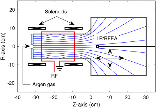
Figure 1. Schematic of the Chi Kung reactor showing the locations of the solenoids, RF antenna, gas inlet, insulating glass plate in the source region and diagnostic probes. The magnetic field lines generated by the solenoids are pictured as blue lines. The Langmuir probe (LP) and retarding field energy analyzer (RFEA) possessed an axial range of −20 ≤ Z ≤ 30 cm and a radial range of −14 ≤ R ≤ 14 cm.
A Langmuir probe (LP) was used to measure the ion saturation current (probe biased to –67 V) downstream of the double layer, located just upstream of the source aperture between –9 and 0 cm. The probe consisted of a one-sided 1.5 mm radius nickel disk installed at the end of a 5 cm long piece of alumina tube, itself fixed to a grounded probe shaft. The probe was free to move both axially and radially without breaking vacuum, allowing for an axial range of −20 ≤ Z ≤ 30 cm and a radial range of −14 ≤ R ≤ 14 cm. Ion saturation currents were acquired and fast Fourier transformed by a National Instruments NI PXI-5122 high-speed digitizer (100 MHz sampling rate), prior to further analysis.
Ion densities downstream of the double layer were obtained employing a retarding field energy analyser (RFEA) operating in ion collection mode. The RFEA follows a design published previously in Charles and Boswell [8] and consists of a stack of biased nickel grids positioned in front of a nickel collector plate. The grids act as a directional energy filter for ions accelerated by the grounded sheath surrounding the RFEA and entering the probe orifice. In ion mode operation, the RFEA repeller grid is aligned perpendicular to the ion beam and biased to –80 V and the applied discriminator voltage Vd is scanned between 0 and 80 V. Those ions with sufficient kinetic energy to overcome the potential barrier provided by the discriminator grid are measured as an integrated ion current at the collecting electrode, Ic(Vd).
As Vd is swept from 0 to 80 V, the increasing potential barrier between the discriminator grid and the collecting plate results in a decrease in the current incident upon the collector plate. Eventually, Vd becomes too large and no ions are detected at the collecting electrode. The total stationary ion current can then be extracted by applying a Gaussian fit to the first derivative of RFEA I-V trace, and converted into the stationary ion density via comparison to the stationary ion current measured via a Langmuir probe, as performed and described in Bennet et al. [22].
An instability in the ion saturation current has been observed in the expansion chamber of the Chi Kung reactor under conditions known to support an ion beam [21]. A representative example of the instability measured in a 13.56 MHz, 300 W, 0.25 mTorr argon discharge is shown in Figure 2A, indicating the maximum amplitude ξ and central frequency νξ. The radial distribution in the maximum instability amplitude and the radial ion density gradient are shown in Figure 2B, as measured downstream of the DL (Z = 2 cm) for the same operating conditions. Ion density measurements were obtained between 0 ≤ R ≤ 10 cm employing identical conditions for a 0.30 mTorr operating pressure.
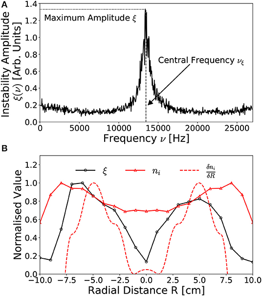
Figure 2. Representative examples of (A) the fourier transformed ion saturation current measured off-axis (R, Z = –6 cm, 2 cm) downstream of the DL, exhibiting an anomalous instability centered on νξ = 13.4 kHz with a 2 kHz FWHM bandwidth and (B) the radial distribution (at Z = 2 cm) in the maximum instability amplitude ξ, the ion density ni and the radial ion density gradient . Solid lines added to guide the eye. Operating conditions: helicon antenna supplied Prf = 300 W at νrf = 13.56 MHz employing 0.25–0.30 mTorr argon with I1,2 = 6 A solenoid current.
The instability shown in Figure 2A represents an ion acoustic wave at νξ = 13.4 kHz propagating downstream of the DL (R, Z = –6 cm, 2 cm). Notably, this frequency does not correspond to any harmonic or alias of the driving 13.56 MHz frequency nor to the ion cyclotron resonance frequency, instead arising from anomalous periodic interactions within the plasma. The relative amplitude and frequency range of the instability agree with previously measured anomalous signals observed under similar operating conditions, presented in Aanesland et al. [39].
The spatial distribution in the amplitude of the instability, shown in Figure 2B for −10 ≤ R ≤ 10 cm at Z = 2 cm, exhibits two approximately symmetric maxima located R~5–6 cm off-axis, reducing on-axis and adjacent to the expansion chamber walls. Additionally Figure 2B contains the normalized radial ion density profile measured between 0 ≤ R ≤ 10 cm employing an axially aligned RFEA positioned at the same axial location, where ion density data is obtained from Bennet et al. [22]. The radial density profile shows the high-density conics as locations of increased ion density off axis centered around R ~7–8 cm [15, 22]. The amplitude of the instability drops rapidly toward the regions of peak ion density, limiting its radial extent to within the conics. In fact, the radial distribution of the instability demonstrates maxima corresponding with the regions of highest increasing radial ion density gradient. To illustrate this, the radial ion density gradient , obtained from a differentiated smoothing spline fit of the radial ion density, has been plotted on Figure 2B, where features two peaks located off-axis which align closely with the peaks of the instability amplitude. This indicates that the observed instability could be caused by the radial density gradient in the downstream generated by the conics. Note that the ion density in Figure 2B was measured only on the +R side, with the ion density and density gradient for the –R side presented as a symmetric mapping.
To further investigate the dependencies between the spatial distribution of the instability and the radial ion density gradients, LP measurements of the instability magnitude and central frequency were performed with a 1 cm radial and axial resolution across the mid-plane downstream of the Chi-Kung source. The central frequency of the instability downstream of the DL was found to be approximately spatially invariant, however the amplitude of the instability exhibited both a radial and axial spatial variation. A 2D map of the maximum amplitude of the instability is shown in Figure 3A for a 13.56 MHz, 300 W, argon discharge at 0.25 mTorr. Figure 3B shows a 2D map of the normalized radial ion density gradient, again employing smoothing splines allowing for calculation of throughout the measured area.
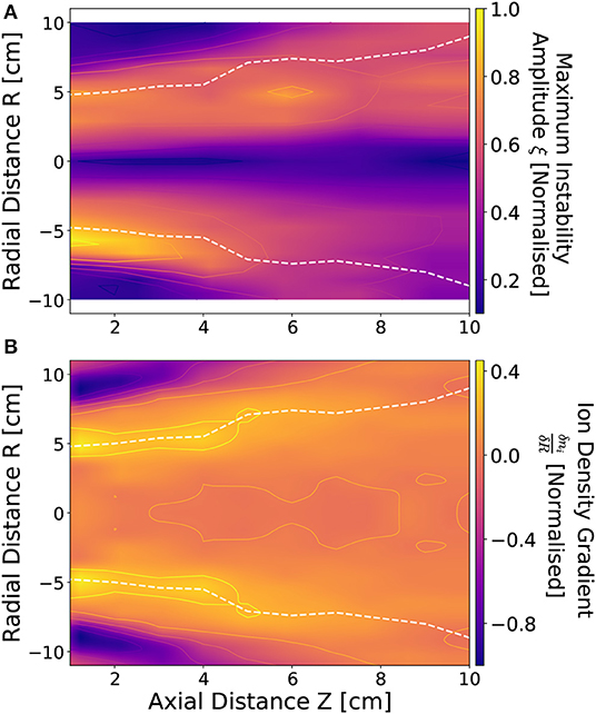
Figure 3. Normalized (A) maximum instability amplitude ξ and (B) radial ion density gradient downstream of the DL between 1 ≤ Z ≤ 10 cm and −10 ≤ R ≤ 10 cm. White dashed lines denote the approximate location of beam-conic interface. Operating conditions: helicon antenna supplied Prf = 300 W at νrf = 13.56 MHz employing 0.25 mTorr argon with I1,2 = 6 A solenoid current.
As observed previously in Figure 2, a similarity exists between the topography of the instability amplitude and the most positive , exhibited in Figures 3A,B. Both the amplitude of the instability and the radial ion density gradient exhibit maxima coinciding with the beam-conic interface, denoted by the white dashed lines. The beam-conic interface marks the transition from the low density, high ion energy conditions on-axis into the high density, low ion energy conics.
In addition, there exists a “global” radial asymmetry in the topology of the instability, with the highest instability amplitudes measured for the –R side of the Chi-Kung reactor. This global asymmetry likely arises from the rf antenna geometry, where higher average instability amplitudes coincide with the “hot” –R (R < 0 cm) side of the antenna, while the lower average instability amplitudes align with the “cold” +R (R > 0 cm) grounded end of the antenna. Note that due to the radial mirroring of the ion density measurements, performed on the “cold” +R side of the source, this asymmetry is not observed in Figure 3B. Previous work employing similar operational conditions have observed an asymmetric ion density distribution about the central axis, with the higher ion density localized to the –R side of the reactor [22]. From the topological comparisons of the instability to the ion density gradients presented in Figures 2B, 3 it is likely that the instability forms either as a result of ion acoustic interactions across the beam-conic interface [23, 24], or as a density gradient driven drift wave instability [32, 33].
Before attempting to modulate the radial ion density gradients via the introduction of a voltage waveform amplitude modulation, the behavior of the instability was first investigated with respect to the applied rf power Prf, the DC solenoid current I1,2 and the operating argon pressure. These findings are presented in section 3.1, where measurements of the ion saturation current were performed as described previously with reference to Figure 3, employing a radial scan across −10 ≤ R ≤ 10 cm at Z = 2 cm downstream of the DL.
The instability amplitude and central frequency are shown with respect to varying applied power for a 0.25 mTorr pressure, 6 A solenoid current discharge in Figures 4A,D, respectively, with respect to varying solenoid current for a 300 W, 13.56 MHz, 0.25 mTorr pressure discharge in Figures 4B,E, respectively and with respect to varying operating pressure for a 300 W, 6 A solenoid current discharge in Figures 4C,F, respectively. Measurements were taken by employing a LP downstream (Z - 2 cm) of the Chi-Kung source, positioned on-axis (R = 0.0 cm) and at the radial beam-conic interfaces (R = ±5 cm).
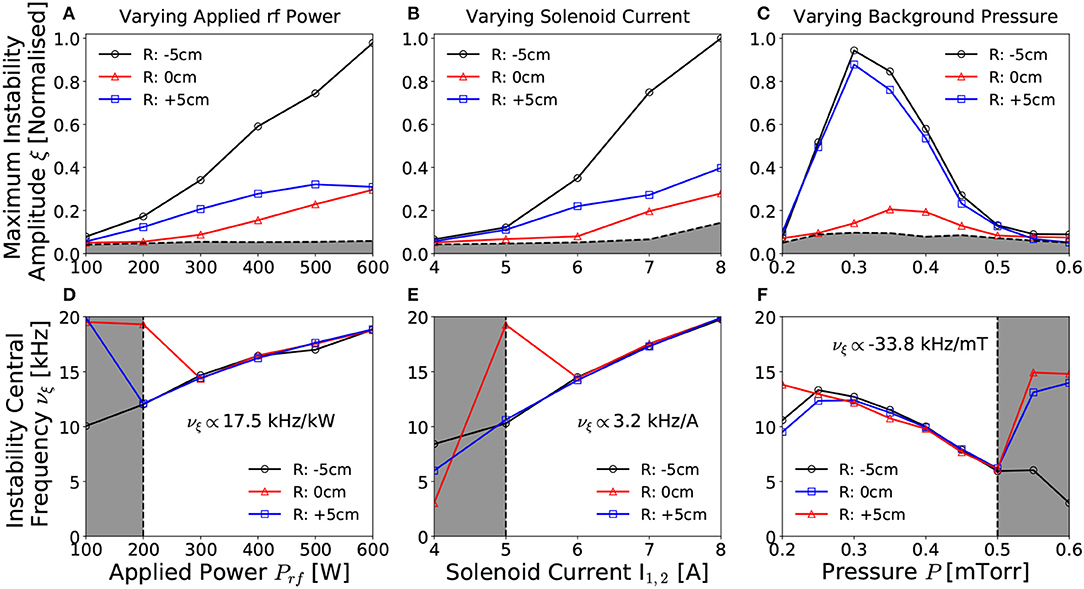
Figure 4. Normalized instability amplitude and frequency with respect to (A,D) rf power Prf, (B,E) solenoid current I1,2 and (C,F) operating argon pressure respectively, as measured on-axis (R = 0.0 cm) and off-axis (R = ±5 cm), Z = 2 cm downstream of the DL. Off-axis measurements correspond to the beam-conic interface, correlating with the region of highest radial ion density gradient. The horizontal gray shaded regions in (A–C) denote the background noise level, while the vertical gray shaded regions in (E–F) denote measurements for which SNR ≤ 2. Solid lines added to guide the eye. Operating conditions: helicon antenna supplied Prf = 100 − 600 W at νrf = 13.56 MHz employing 0.2–0.6 mTorr argon with I1,2 = 4 − 8 A solenoid current.
Increasing the applied antenna power results in a proportional increase in the amplitude of the instability, shown in Figure 4A, where the constant of proportionality varies with radial location. Generally however, a factor of three increase in the rf power relates to an order of magnitude increase in the amplitude of the instability. The spatial distribution continues to exhibit two maxima coinciding with the ±R beam-conic interfaces, as observed previously for Figure 3A. Note that the ratio between the maximum amplitude measured at the “hot” –R and “cold” +R sides of the chamber increases with increasing applied rf power. While this is likely due to an increasing asymmetry between the –R and +R ion density gradients, it should be noted that other plasma conditions, such as the localized electric field adjacent to the antenna, may have an influence on the plasma stability. Note however, in contrast to the instability amplitude, the frequency of the instability in Figure 4D remains spatially invariant and exhibits a linear dependence on the applied rf power, increasing at a rate of 17.5 kHz kW−1, corresponding to a doubling in central frequency for a factor three increase in rf power.
Previous studies of the Chi-Kung reactor and similar inductively coupled rf coupled plasma sources observed an approximately linear relationship between the applied power and the maximum plasma density [5, 21, 43]. This increase is typically not spatially homogeneous, but instead the maximum density increase is localized on-axis, leading to enhanced radial density gradients [22]. The observed correlation between these proportionalities with the topological similarities observed previously between Figures 3A,C supports the hypothesis that the instability is indeed primarily influenced by the ion density distribution across the beam-conic interface.
The axial magnetic field strength was controlled by altering the DC current supplied to the solenoids, where a symmetrical current I1,2 = I1 = I2 was supplied for all cases in Figure 4. The instability is first observed above background noise in Figure 4B for I1,2 ≥ 5 A (≈ 125 G on-axis) agreeing with previously determined minimum solenoid currents required for ion beam formation [44]. The amplitude and frequency of the instability increase in proportion to the solenoid current, shown in Figures 4B,E, exhibiting an order of magnitude increase in the maximum amplitude for a doubling of the applied solenoid current. Such behavior is to be expected due to the increased radial confinement giving rise to enhanced axial and radial ion density gradients within the source [11, 22]. Increasing the radial confinement also amplifies any inherent radial asymmetry in the ion density arising from the antenna geometry, again resulting in higher maximum instability amplitudes on the “hot” –R side of the chamber as compared to the “cold” +R side.
The central frequency of the instability exhibits an approximately linear 3.1 kHz A−1 proportionality to the applied solenoid current, shown in Figure 4E, and remains spatially invariant for currents known to produce an ion beam. Here, a doubling of the solenoid current exhibits a factor of four increase in the frequency of the instability. Note also that reversing the orientation of the magnetic field had no effect on the frequency, amplitude or radial asymmetry of the instability.
Both the amplitude and frequency of the instability exhibited the greatest response to variations in the operating pressure, shown in Figures 4C,F, respectively. Here, the instability is observed for pressures between 0.25 and 0.50 mTorr, agreeing with the measured range in Aanesland et al. [38], and the lower limit of which corresponds to the minimum pressure for ion beam formation [8, 15, 21]. The rapid growth in the amplitude of the instability (off-axis) for increasing pressure between 0.20 and 0.30 mTorr suggests that the presence of an ion beam may be necessary for the formation of the instability. Beyond 0.30 mTorr the amplitude of the instability exhibits an inversely proportional relationship to the operating pressure, falling below the background noise for pressures above 0.50 mTorr. Note that the global asymmetry in the amplitude of the instability between the “hot” –R and “cold” +R sides of the reactor is less pronounced with changes in operating pressure than with power or solenoid current.
The frequency of the instability, shown in Figure 4F, exhibits an inversely proportional relationship with the operating pressure, varying by –33.8 kHz mTorr−1 between 0.25 and 0.50 mTorr, or a factor three reduction in the central frequency for a doubling of the pressure. Increasing the operating pressure results in an increased ionization rate, reducing the on-axis confinement, potentially leading to reduced radial ion density gradients. In addition to altering the radial ion density gradient, previous work has shown that the potential drop across the DL, and hence the ion beam energy and flux, reduces with increasing operating pressure [21]. Therefore, a reduction in the ion beam energy, coupled with the reduced radial ion density gradient, reduces the instability amplitude and frequency, as observed in Figures 4C,F, resulting in a greater influence than that exerted by varying the applied power or solenoid current.
The characterization performed in section 3 indicates a relationship between the radial ion density gradient and the amplitude and frequency of the instability. Further, the appearance of the instability at operating pressures corresponding to the limiting conditions for ion beam formation suggest a link between the two phenomena. Control and reduction of the instability may therefore impact the ion beam parameters. Such control may be achieved through altering the radial ion density gradient, implemented in this work through the application of voltage waveform amplitude modulations.
Voltage waveform amplitude modulation was employed to produce variable frequency and amplitude ion acoustic waves, i.e., time varying ion density fluctuations, within the Chi-Kung source. Voltage waveform amplitude modulation involves the superposition of two non-harmonic sinusoidal voltage waveforms; consisting of a high frequency “carrier” waveform, facilitating power coupling to the plasma, and a low frequency “envelope” waveform, introducing the desired ion acoustic wave but otherwise not significantly affecting the average power deposition. The resulting voltage waveform ϕrf(t) is described by Equation (1):
where, Vrf and Vmod are the carrier and modulation voltage amplitudes, respectively and νrf and νmod represent the carrier and modulation frequencies, respectively. As the modulation voltage is applied symmetrically about the mean carrier voltage, the power deposited into the source remains approximately constant so long as Vmod ≤ Vrf. Modulation frequencies in the range 1 ≤ νmod ≤ 12000 Hz were employed, while the carrier frequency was maintained at νrf = 13.56 MHz. For ease of discussion, the extent to which the carrier waveform is modulated is discussed in terms of the modulation fraction ϕmod, defined as the fraction of the modulation amplitude with respect to the carrier waveform ϕrf within a single modulation phase cycle τmod.
In practice, voltage amplitude modulation was achieved through applying a seed envelope voltage waveform, supplied by a Siglent SDG 5162 waveform generator, to the “volume” input on the ENI OEM-25 power supply, directly varying Vmod. An example of a modulated voltage waveform generated in this way is shown in Figure 5.
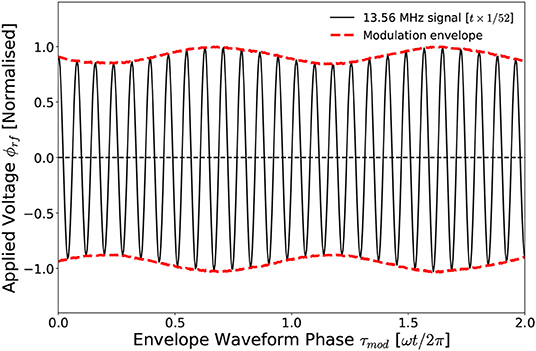
Figure 5. Example of rf amplitude modulation where the base frequency of νrf = 13.56 MHz is modulated at νmod = 8 kHz by a modulation fraction of ϕmod = 0.16. For clarity the 13.56 MHz signal is plotted at temporal scale.
The voltage waveform in Figure 5 consists of a base 13.56 MHz voltage frequency, modulated at νmod = 8 kHz by a modulation fraction of ϕmod = 0.16 ϕrf. Ions within the source chamber, being heavier and less mobile than the electrons, will respond preferentially to the low-frequency component of the modulated waveform. Ion acoustic waves induced by the kHz modulation voltage are then free to propagate through the source chamber and into the downstream region. Altering the modulation amplitude and frequency therefore provides a means of selectively influencing the ion dynamics, providing a control mechanism for the ion density gradients across the ion beam-conic interface. The application of voltage amplitude modulation can therefore be used to investigate and control the instability characterized in section 3.
As an initial proof of concept, a voltage waveform amplitude modulation of frequency νmod = 1 Hz and modulation fraction ϕmod = 0.5 ϕrf was applied to the 13.56 MHz carrier waveform, as described in section 4.1, for a Prf = 300 W, I1,2 = 6 A, 0.25 mTorr argon discharge. The resulting temporally-averaged and temporally-resolved LP ion saturation current measurements of the instability amplitudes measured off-axis downstream of the DL (R, Z = –6 cm, 2 cm) are shown in Figures 6A,B, respectively.
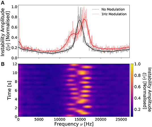
Figure 6. Normalized (A) time-integrated instability amplitude profiles with (red curve) and without (black curve) a νmod = 1 Hz, ϕmod = 0.5ϕrf voltage amplitude modulation and (B) time-resolved instability profiles employing the same voltage amplitude modulation. Instability measured at the beam-conic interface (R = –6 cm) downstream of the DL (Z = 2 cm). Solid lines in (A) were smoothed employing a SavitzkyGolay filter. Operating conditions: helicon antenna supplied Prf = 300 W at νrf = 13.56 MHz employing 0.25 mTorr argon with I1,2 = 6 A solenoid current.
Figure 6A indicates that, in the absence of an applied amplitude modulation, the instability exhibits an approximately Gaussian frequency space profile centered at 14.2 kHz, agreeing with previous observations. Upon application of a 1 Hz voltage modulation the instability profile splits into a bi-modal distribution, consisting of a low amplitude, low frequency (≈ 12.6 kHz) component and a high amplitude, high frequency (≈ 15.7 kHz) component. This “smearing” of the instability over a wider frequency range arises due to the periodic alteration in the applied rf power, following the proportionalities exhibited in Figures 4A,B. Varying the power sinusoidally therefore produces a low amplitude, low frequency peak corresponding to the minima of the envelope waveform and a high amplitude, high frequency peak corresponding to the maxima of the envelope waveform. This is more clearly visualized in the temporally resolved instability amplitude, shown in Figure 6B, illustrating approximately 12 voltage amplitude modulation cycles. Note that the LP measurement timescale and the νmod = 1 Hz amplitude modulation timescale are not synchronized, resulting in a beat-effect where the instability is measured at different phases of the amplitude modulation.
Recalling that the amplitude of the instability varies with respect to the radial ion density gradient across the beam-conic interface, see Figures 3A,B, it is plausible that effects arising from the voltage amplitude modulation in this “low-frequency” regime are influenced not only by the ion acoustic wave density perturbations δni(τmod), but also by variations in the stationary ion density gradients , the latter of which follow trends observed in Figures 4A,B described by Equation (2):
Such behavior is indicative of a modulation timescale low enough such that the stationary ion density is capable of responding. Increasing the applied modulation frequency results in a reduced “frequency smearing” effect, previously observed in Figure 6B, indicating a decreasing temporal variation in the stationary ion density gradient. For modulation frequencies in excess of νmod ≥ 2 kHz the instability exhibits no evidence of a frequency smearing effect, indicating a constant stationary radial ion density gradient. The time-resolved radial ion density gradient, described by Equation (3), can therefore be expected to consist of a time-invariant stationary density superimposed with a time-varying ion density perturbation, induced by the modulation voltage:
This “high-frequency” regime presents the capability to influence the instability through specifically varying the amplitude and frequency of the ion density perturbations. The remainder of this study addresses the degree to which the instability can be controlled within the high-frequency modulation regime.
The frequency distribution of the instability for three applied νmod = 2 kHz voltage amplitude modulations in a Prf = 300 W, I1,2 = 6 A, νrf = 13.56 MHz, 0.42 mTorr discharge are shown in Figure 7A, with the corresponding maximum instability amplitude shown with respect to varying amplitude modulation fraction between 0.0 ϕrf ≤ ϕmod ≤ 0.74 ϕrf presented in Figure 7B.
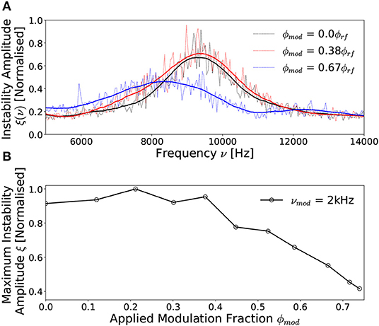
Figure 7. Normalized instability amplitude profiles as measured at the beam-conic interface downstream of the DL (R, Z = –6 cm, 2 cm) with a νmod = 2 kHz voltage amplitude modulation for (A) ϕmod = 0.0 ϕrf, ϕmod = 0.38 ϕrf and ϕmod = 0.67 ϕrf and (B) the variation in peak instability amplitude with respect to increasing ϕmod. Solid lines in (A) were smoothed employing a SavitzkyGolay filter and included in (B) to guide the eye. Operating conditions: helicon antenna supplied Prf = 300 W at νrf = 13.56 MHz employing 0.42 mTorr argon with I1,2 = 6 A solenoid current.
The unmodulated (ϕmod = 0.0) instability in Figure 7A exhibits an approximately Gaussian frequency distribution with a central frequency of 9.2 kHz, lower than that observed in Figure 2A, due to the increased operating pressure. Applying a νmod = 2 kHz, ϕmod = 0.38 ϕrf voltage amplitude modulation has no significant affect on the instability, altering neither the amplitude nor the central frequency. The preservation of a Gaussian frequency profile differs from that observed previously at νmod = 1 Hz in Figure 6A demonstrating independence from the time-varying rf power indicating a high-frequency modulation regime. It should be noted that the transition between the low-frequency to high-frequency regimes is relatively gradual with increasing modulation frequency. As such νmod = 2 kHz represents an empirically chosen frequency marking this transition as it is the lowest modulation frequency for which evidence of a bi-modal distribution is on-par with the background noise level. Increasing the modulation fraction beyond ϕmod ≥ 0.4 ϕrf results in a significant reduction in both the amplitude and central frequency of the instability, albeit also extending the frequency range. The spreading of the instability in frequency space may arise from non-linear coupling between the instability and the modulation frequency [29]. Evidence of this may be observed from a comparison of Figures 6, 7, where for a νmod = 1 Hz modulation, the highest amplitude component of the instability is up-modulated from 14.2 to 15.7 kHz. In comparison, for a νmod = 2 kHz modulation, the central frequency of the instability is down-modulated from 9.2 to 8.1 kHz. While these demonstrate the potential for coupling between the modulation frequency and the instability frequency, a full analysis of this phenomena is beyond the scope of this work.
The amplitude of the instability is shown with respect to applied modulation fraction in Figure 7B, exhibiting a limited variation in the amplitude of the instability between 0.0 ϕrf ≤ ϕmod ≤ 0.4 ϕrf, followed by a significant reduction beyond ϕmod ≈ 0.4 ϕrf. The inversely proportional relationship follows an approximately linear trend between 0.4 ϕrf ≤ ϕmod ≤ 0.74 ϕrf, with ξ reducing by 50%, at which point the voltage amplitude modulation fraction was limited by the internal response time of the rf power supply.
The observed variation in the amplitude of the instability with respect to increasing modulation fraction suggests that the ion acoustic waves are altering the time-averaged radial ion density gradient across the beam-conic interface. Assuming a time-invariant stationary ion density and time-varying ion density perturbation from Equation (3), the resulting time-averaged radial ion density gradient can be described by Equation (4).
Here, the ion density perturbation varies in proportion to the applied modulation voltage waveform δni(τmod) ∝ sin(2πνmodt), via Equation (1). Ignoring wave damping and assuming a homogeneous stationary ion density, this would result in a temporally symmetric modification of the radial density gradient, leading to a zero time-averaged contribution from the perturbation.
However for ion acoustic waves traveling through an inhomogeneous medium, as is the case here, the amplitude of the acoustic wave is attenuated with respect to the density of the background medium. Notably, ion acoustic waves propagating radially within the downstream region experience an increasing stationary ion density, see Figure 3B. The positive amplitude (compressive) phase of the wave is therefore likely to experience a higher energy loss than the negative amplitude (rarefaction) phase leading to an asymmetric attenuation of the ion acoustic waveform. The resulting ion density perturbation would therefore be expected to exhibit an amplitude asymmetry, represented in Figure 8.
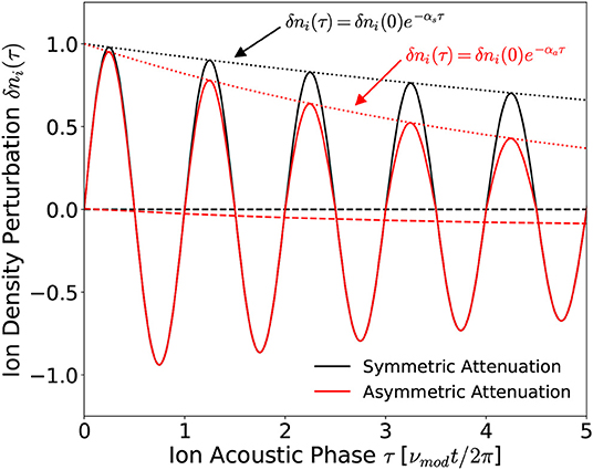
Figure 8. Representative ion acoustic waveforms exhibiting symmetric αs and asymmetric αa amplitude attenuations. The time-averaged values and positive amplitudes of the waveforms are denoted by the dashed and dotted lines, respectively.
The symmetrically attenuated waveform in Figure 8 exhibits a zero time-averaged value, agreeing with Equation (5). In contrast, the asymmetrically attenuated ion acoustic wave exhibits a non-zero time-averaged ion density perturbation, such that:
Ion acoustic waves possessing a negative amplitude asymmetry, such as those shown in Figure 8 where the negative amplitude of the wave exceeds the positive amplitude, are therefore expected to reduce the time-averaged ion density gradient, via Equation (4), leading to a reduction in the amplitude of the instability. These expected outcomes concur with the measured direction of the ion density gradient in Figure 2B and the associated reduction in the amplitude of the instability in Figures 7A,B. In addition, note that the magnitude of the time-averaged asymmetry increases with the number of ion acoustic phase cycles, i.e., for a fixed source dimension the attenuation of an sub-cyclotronic ion acoustic wave increases in proportion to the applied frequency [45]. Therefore, increasing the voltage modulation frequency would be expected to enhance the effects observed for νmod = 2 kHz, further reducing the magnitude of the instability.
To investigate the effects of increasing the applied modulation frequency, Figure 9 shows the maximum instability amplitude with respect to modulation fraction for modulation frequencies in the range 2 ≤ νmod ≤ 12 kHz for a 300 W, 13.56 MHz, I1,2 = 6 A, 0.42 mTorr discharge. The instability amplitudes are measured R = –6 cm off-axis, Z = 2 cm downstream of the DL corresponding to the location of peak instability amplitude, see Figure 3A.
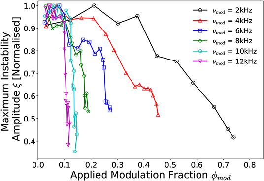
Figure 9. Normalized instability amplitude profiles as measured at the beam-conic interface downstream of the DL (R, Z = –6 cm, 2 cm) with respect to voltage amplitude modulation frequency 2 kHz ≤ νmod ≤ 12 kHz and modulation fraction 0.0 ≤ ϕmod ≤ 0.74. Solid lines added to guide the eye. Operating conditions: helicon antenna supplied Prf = 300 W at νrf = 13.56 MHz employing 0.42 mTorr argon with I1,2 = 6 A solenoid current.
The instability amplitudes in Figure 9 were found to be inversely proportional to the frequency of the voltage amplitude modulation, i.e., increasing the modulation frequency results in a substantial reduction in the amplitude of the instability for the same modulation fraction. Quantifying this observation employing a least-squares exponential fit yields that for a fixed reduction in instability amplitude, the required modulation fraction varies as: . This effect saturates as the modulation frequency is increased, trending toward a minimum required modulation fraction of ϕmod ≈ 0.1ϕrf. These findings are concurrent with the hypothesis that asymmetrically attenuated ion acoustic waves are responsible for a reduction in the radial ion density gradient, via Equation (4), and subsequently also the amplitude of the instability.
Employing a νmod = 12 kHz, ϕmod = 0.11 ϕrf voltage amplitude modulation, the maximum amplitude of the instability was reduced by up to 65%. The central frequency of the instability (not shown) remained approximately independent of the applied modulation frequency, varying by at most 13% (1.2 kHz) over the range 0.0 ≤ ϕmod ≤ 0.74 for the νmod = 2 kHz modulation case. It should be noted that these trends are representative of the behavior of the instability obtained from a single spatial location (R, Z = –6 cm, 2 cm) downstream of the DL. However, as the induced ion density perturbations are not limited to any particular region of the source or expansion region, reduction of the instability amplitude is expected to be observed over the full downstream region.
Figure 10 shows the radially resolved maximum instability amplitudes as measured Z = 2 cm downstream of the DL between −10 cm ≤ R ≤ 10 cm, for a 300 W, 13.56 MHz, I1,2 = 6 A, 0.42 mTorr argon discharge employing a νmod = 12 kHz voltage amplitude modulation where ϕmod = 0.0ϕrf (i.e. no modulation) and ϕmod = 0.11ϕrf.
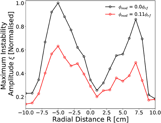
Figure 10. Radially resolved (−10 cm ≤ R ≤ 10 cm) instability amplitude downstream of DL (Z = 2 cm) employing a with a variable 12 kHz voltage amplitude modulation fraction. Solid lines added to guide the eye. Operating conditions: helicon antenna supplied Prf = 300 W at νrf = 13.56 MHz employing 0.42 mTorr argon with I1,2 = 6 A solenoid current.
In the absence of an applied voltage amplitude modulation the spatial distribution of the instability in Figure 10 agrees with that previously measured in Figure 3A. The application of a νmod = 12 kHz, ϕmod = 0.11 ϕrf voltage amplitude modulation results in reduced instability amplitudes at all radii. The effect is most pronounced at the beam-conic interfaces (R = –5 cm, R = +6 cm), reducing on-axis and toward the downstream chamber walls. Greater inhibition of the instability adjacent to the beam-conic interface suggests a spatially varying modification of the radial ion density gradient arising from the voltage amplitude modulation. While this may arise from a number of effects, it is consistent with an increasing δni contribution arising from increasingly asymmetric ion acoustic waves attenuated through a radially varying ion density gradient. The trends presented in Figures 7, 9, 10, supported by the mathematical framework introduced in section 4.2, demonstrate voltage amplitude modulation as an effective technique for the reduction of ion density driven instabilities in magnetized plasmas.
A kHz instability in the ion saturation current downstream of a current free double layer has been spatially characterized with respect to the operating pressure, applied rf power and on-axis magnetic field strength. The amplitude of the instability was found to vary in proportion to the radial ion density gradient across the ion beam-conic interface. Reduction of the instability was achieved through the application of a kHz frequency voltage amplitude modulation νmod to the “carrier” 13.56 MHz voltage waveform ϕrf. Two amplitude modulation regimes were identified: a “low-frequency” regime (1 Hz ≤ νmod ≤ 2 kHz), characterized by a temporal “smearing” effect, where the instability is primarily influenced through variations in the time-averaged stationary ion density and a ‘high-frequency’ regime (νmod ≥ 2 kHz) where the instability is primarily influenced via induced ion acoustic wave density perturbations. Employing a νmod = 12 kHz, ϕmod = 0.11 ϕrf voltage amplitude modulation, the amplitude of the instability was reduced by up to 65%. Measurements of the ion energy distribution downstream of the double layer indicated an increased proportion of high energy ions within the ion beam, coinciding with a reduction in the instability amplitude. The application of voltage amplitude modulation has the potential to be employed as an effective technique for the reduction of ion density driven instabilities in magnetized plasmas.
The datasets generated for this study are available on request to the corresponding author.
SD: measurement of data, analysis of data, and preparation of manuscript. AB: lab assistance, preparation of manuscript introduction, and editing. DT and RB: lab assistance and editing. JD: editing. CC: project coordinator, lab facilities host, lab assistance, and editing.
This work presented herein was carried out within the SP3 lab at the Australian National University and funded by the Engineering and Physical Sciences Research Council (EPSRC), grant reference number: EP/m508196/1.
The authors declare that the research was conducted in the absence of any commercial or financial relationships that could be construed as a potential conflict of interest.
The authors wish to thank Peter Alexander for technical support and gratefully acknowledge support from the Norma Ann Christie Scholarship in Low Temperature Plasma Physics.
1. Adamovich I, Baalrud SD, Bogaerts A, Bruggeman PJ, Cappelli M, Colombo V, et al. The 2017 Plasma Roadmap: low temperature plasma science and technology. J Phys D Appl Phys. (2017) 50:323001. doi: 10.1088/1361-6463/aa76f5
2. Mazouffre S. Electric propulsion for satellites and spacecraft: established technologies and novel approaches. Plasma Source Sci Technol. (2016) 25:033002. doi: 10.1088/0963-0252/25/3/033002
3. Charles C. Grand challenges in low-temperature plasma physics. Front Phys. (2014) 2:39. doi: 10.3389/fphy.2014.00039
4. Charles C. Plasmas for spacecraft propulsion. J Phys D Appl Phys. (2009) 42:163001. doi: 10.1088/0022-3727/42/16/163001
5. Lafleur T, Takahashi K, Charles C, Boswell RW. Direct thrust measurements and modelling of a radio-frequency expanding plasma thruster. Phys Plasmas. (2011) 18:1–4. doi: 10.1063/1.3610570
6. West MD, Charles C, Boswell RW. Testing a helicon double layer thruster immersed in a space-simulation chamber. J Propul Power. (2008) 24:134–41. doi: 10.2514/1.31414
7. Charles C, Boswell RW. Effect of exhaust magnetic field in a helicon double-layer thruster operating in Xenon. IEEE Trans Plasma Sci. (2008) 36:2141–6. doi: 10.1109/TPS.2008.2004233
8. Charles C, Boswell RW. Laboratory evidence of supersonic ion beam generated by a current-free “helicon” double-layer. Phys Plasmas. (2004) 11:1706–14. doi: 10.1063/1.1652058
9. Charles C, Boswell R. Current-free double-layer formation in a high-density helicon discharge. Appl Phys Lett. (2003) 82:1356–8. doi: 10.1063/1.1557319
10. Zhang Y, Charles C, Boswell R. Effect of radial plasma transport at the magnetic throat on axial ion beam formation. Phys Plasmas. (2016) 23:083515. doi: 10.1063/1.4960828
11. Lafleur T, Charles C, Boswell RW. Ion beam formation in a very low magnetic field expanding helicon discharge. Phys Plasmas. (2010) 17:1–6. doi: 10.1063/1.3381093
12. Byhring HS, Charles C, Fredriksen A, Boswell RW. Double layer in an expanding plasma: simultaneous upstream and downstream measurements. Phys Plasmas. (2008) 15:102113. doi: 10.1063/1.3002396
13. Plihon N, Chabert P, Corr CS. Experimental investigation of double layers in expanding plasmas. Phys Plasmas. (2007) 14:013506. doi: 10.1063/1.2424429
14. Sun X, Keesee AM, Biloiu C, Scime EE, Meige A, Charles C, et al. Observations of ion-beam formation in a current-free double layer. Phys Rev Lett. (2005) 95:025004. doi: 10.1103/PhysRevLett.95.025004
15. Cox W, Charles C, Boswell RW, Hawkins R. Spatial retarding field energy analyzer measurements downstream of a helicon double layer plasma. Appl Phys Lett. (2008) 93:2006–9. doi: 10.1063/1.2965866
16. Ahedo E, Merino M. Two-dimensional plasma expansion in a magnetic nozzle : separation due to electron inertia. Phys Plasmas. (2012) 19:083501. doi: 10.1063/1.4739791
17. Charles C. High density conics in a magnetically expanding helicon plasma. Appl Phys Lett. (2010) 96:051502. doi: 10.1063/1.3309668
18. Saha SK, Chowdhury S, Janaki MS, Ghosh A, Hui AK, Raychaudhuri S. Plasma density accumulation on a conical surface for diffusion along a diverging magnetic field. Phys Plasmas. (2014) 21:043502. doi: 10.1063/1.4870758
19. Takahashi K, Akahoshi H, Charles C, Boswell RW, Ando A. High temperature electrons exhausted from rf plasma sources along a magnetic nozzle a magnetic nozzle. Phys Plasmas. (2017) 24:084503. doi: 10.1063/1.4990110
20. Gulbrandsen N, Fredriksen Å. RFEA measurements of high-energy electrons in a helicon plasma device with expanding magnetic field. Front Phys. (2017) 5:2. doi: 10.3389/fphy.2017.00002
21. Bennet A, Charles C, Boswell R. In situ electrostatic characterisation of ion beams in the region of ion acceleration. Phys Plasmas. (2018) 25:023516. doi: 10.1063/1.5017049
22. Bennet A, Charles C, Boswell R. Separating the location of geometric and magnetic expansions in low-pressure expanding plasmas. Plasma Sources Sci Technol. (2018) 27:075003. doi: 10.1088/1361-6595/aacd6d
23. Thakur SC, Harvey Z, Biloiu IA, Hansen A, Hardin RA, Przybysz WS, et al. Increased upstream ionization due to formation of a double layer. Phys Rev Lett. (2009) 102:1–4. doi: 10.1103/PhysRevLett.102.035004
24. Thakur SC, Hansen A, Scime EE. Threshold for formation of a stable double layer in an expanding helicon plasma. Plasma Sources Sci Technol. (2010) 19:025008. doi: 10.1088/0963-0252/19/2/025008
25. Allan W, Sanderson JJ. Temperature gradient drive ion acoustic instability. Plasma Phys. (1974) 16:753. doi: 10.1088/0032-1028/16/8/005
26. Priest ER, Sanderson JJ. Ion acoustic instability in collisionless shocks. Plasma Phys. (1972) 14:951. doi: 10.1088/0032-1028/14/10/005
27. Jassby DL. Transverse velocity shear instabilities within a magnetically confined plasma. Phys Fluids. (1972) 15:1590–604. doi: 10.1063/1.1694135
28. Keen BE, Fletcher WHW. Suppression and enhancement of an ion-sound instability by nonlinear resonance effects in a plasma. Phys Rev Lett. (1969) 23:760–3. doi: 10.1103/PhysRevLett.23.760
29. Thakur SC, Brandt C, Cui L, Gosselin JJ, Light AD, Tynan GR. Multi-instability plasma dynamics during the route to fully developed turbulence in a helicon plasma. Plasma Sources Sci Technol. (2014) 23:044006. doi: 10.1088/0963-0252/23/4/044006
30. Yamada T, Itoh SI, Maruta T, Kasuya N, Nagashima Y, Shinohara S, et al. Anatomy of plasma turbulence. Nat Phys. (2008) 4:721–5. doi: 10.1038/nphys1029
31. Burin MJ, Tynan GR, Antar GY, Crocker NA, Holland C. On the transition to drift turbulence in a magnetized plasma column. Phys Plasmas. (2005) 12:1–14. doi: 10.1063/1.1889443
32. Schröder C, Grulke O, Klinger T, Naulin V. Spatial mode structures of electrostatic drift waves in a collisional cylindrical helicon plasma. Phys Plasmas. (2004) 11:4249–53. doi: 10.1063/1.1779225
33. Schröder C, Grulke O, Klinger T, Naulin V. Drift waves in a high-density cylindrical helicon discharge. Phys Plasmas. (2005) 12:1–6. doi: 10.1063/1.1864076
34. Light M, Chen FF, Colestock PL. Low frequency electrostatic instability in a helicon plasma. Phys Plasmas. (2001) 8:4675–89. doi: 10.1063/1.1403415
35. Croes V, Lafleur T, Bonaventura Z, Bourdon A, Chabert P. 2D particle-in-cell simulations of the electron drift instability and associated anomalous electron transport in Hall-effect thrusters. Plasma Sources Sci Technol. (2017) 26:034001. doi: 10.1088/1361-6595/aa550f
36. McDonald MS, Gallimore AD. Rotating spoke instabilities in hall thrusters. IEEE Trans Plasma Sci. (2011) 39:2952–3. doi: 10.1109/TPS.2011.2161343
37. Zhurin VV, Kaufman HR, Robinson RS. Physics of closed drift thrusters. Plasma Sources Sci Technol. (1999) 8:R1–20. doi: 10.1088/0963-0252/8/1/021
38. Aanesland A, Charles C, Lieberman MA, Boswell RW. Upstream ionization instability associated with a current-free double layer. Phys Rev Lett. (2006) 97:1–4. doi: 10.1103/PhysRevLett.97.075003
39. Aanesland A, Lieberman MA, Charles C, Boswell RW. Experiments and theory of an upstream ionization instability excited by an accelerated electron beam through a current-free double layer. Phys Plasmas. (2006) 13:122101. doi: 10.1063/1.2398929
40. Takahashi K, Charles C, Boswell R, Hatakeyama R. Radial characterization of the electron energy distribution in a helicon source terminated by a double layer. Phys Plasmas. (2008) 15:074505. doi: 10.1063/1.2959137
41. Thakur SC, Xu M, Manz P, Fedorczak N, Holland C, Tynan GR. Suppression of drift wave turbulence and zonal flow formation by changing axial boundary conditions in a cylindrical magnetized plasma device. Phys Plasmas. (2013) 20:012304. doi: 10.1063/1.4775775
42. Vaezi P, Holland C, Thakur SC, Tynan GR. Understanding the impact of insulating and conducting endplate boundary conditions on turbulence in CSDX through nonlocal simulations. Phys Plasmas. (2017) 24:042306. doi: 10.1063/1.4980843
43. Lieberman MA, Lichtenberg AJ. Principles of Plasma Discharges and Materials Processing. 2nd ed. Hoboken, NJ: John Wiley & Sons (2005).
44. Charles C, Boswell RW, Cox W, Laine R, MacLellan P. Magnetic steering of a helicon double layer thruster. Appl Phys Lett. (2008) 93:10–3. doi: 10.1063/1.3033201
Keywords: helicon, magnetized plasmas, double-layer, ion-acoustic instability, radio-frequency
Citation: Doyle SJ, Bennet A, Tsifakis D, Dedrick JP, Boswell RW and Charles C (2020) Characterization and Control of an Ion-Acoustic Plasma Instability Downstream of a Diverging Magnetic Nozzle. Front. Phys. 8:24. doi: 10.3389/fphy.2020.00024
Received: 20 November 2019; Accepted: 27 January 2020;
Published: 18 February 2020.
Edited by:
Ashild Fredriksen, Arctic University of Norway, NorwayReviewed by:
Bill Amatucci, United States Naval Research Laboratory, United StatesCopyright © 2020 Doyle, Bennet, Tsifakis, Dedrick, Boswell and Charles. This is an open-access article distributed under the terms of the Creative Commons Attribution License (CC BY). The use, distribution or reproduction in other forums is permitted, provided the original author(s) and the copyright owner(s) are credited and that the original publication in this journal is cited, in accordance with accepted academic practice. No use, distribution or reproduction is permitted which does not comply with these terms.
*Correspondence: Scott J. Doyle, U2NvdHQuRG95bGVAUGh5c2ljcy5vcmc=
Disclaimer: All claims expressed in this article are solely those of the authors and do not necessarily represent those of their affiliated organizations, or those of the publisher, the editors and the reviewers. Any product that may be evaluated in this article or claim that may be made by its manufacturer is not guaranteed or endorsed by the publisher.
Research integrity at Frontiers
Learn more about the work of our research integrity team to safeguard the quality of each article we publish.