- Niels Bohr Institute, University of Copenhagen, Copenhagen, Denmark
Bernaise (Binary Electrohydrodynamic Solver) is a flexible high-level finite element solver of two-phase electrohydrodynamic flow in complex geometries. Two-phase flow with electrolytes is relevant across a broad range of systems and scales, from “lab-on-a-chip” devices for medical diagnostics to enhanced oil recovery at the reservoir scale. For the strongly coupled multi-physics problem, we employ a recently developed thermodynamically consistent model which combines a generalized Nernst–Planck equation for ion transport, the Poisson equation for electrostatics, the Cahn–Hilliard equation for the phase field (describing the interface separating the phases), and the Navier–Stokes equations for fluid flow. We present an efficient linear, decoupled numerical scheme which sequentially solves the three sets of equations. The scheme is validated by comparison to cases where analytical solutions are available, benchmark cases, and by the method of manufactured solution. The solver operates on unstructured meshes and is therefore well suited to handle arbitrarily shaped domains and problem set-ups where, e.g., very different resolutions are required in different parts of the domain. Bernaise is implemented in Python via the FEniCS framework, which effectively utilizes MPI and domain decomposition. Further, new solvers and problem set-ups can be specified and added with ease to the Bernaise framework by experienced Python users.
1. Introduction
Two-phase flow with electrolytes is encountered in many natural and industrial settings. Although Lippmann already in the nineteenth century [1, 2] made the observation that an applied electric field changes the wetting behavior of electrolyte solutions, the phenomenon of electrowetting has remained elusive. Recent decades have seen an increased theoretical and experimental interest in understanding the basic mechanisms of electrokinetic or electrohydrodynamic flow [3, 4]. Progress in micro- and nanofluidics [5, 6] has enabled the use of electrowetting to control small amounts of fluid with very high precision (see e.g., the comprehensive reviews by [2, 7, 8] and references therein). This yields potential applications in, e.g., “lab-on-chip” biomedical devices or microelectromechanical systems [9–11], membranes for harnessing blue energy [12], energy storage in fluid capacitors, and electronic displays [13–16].
It is known that electrohydrodynamic phenomena affects transport properties and energy dissipation in geological systems, as a fluid moving in a fluid-saturated porous medium sets up an electric field that counteracts the fluid motion [17–19]. Electrowetting may also be an important factor in enhanced oil recovery [20, 21]. Here, the injection of water of a particular salinity, or “smart water” [22], is known to increase the recovery of oil from reservoirs as compared to brine [23]. Further, transport in sub-micrometer scale pores in low-permeability rocks in the Earth's crust may be driven by gradients in the electrochemical potential [24], which may have consequences for, e.g., transport of methane-water mixtures in dense rocks.
Hence, a deepened understanding of electrowetting and two-phase electrohydrodynamics would be of both geological and technological importance. While wetting phenomena (or more generally, two-phase flow) on one hand, and electrohydrodynamics on the other, remain in themselves two mature and active areas of research which both encompass a remarkably rich set of phenomena, this article is concerned with the interface between these fields. For interested readers, there are several reviews available regarding wetting phenomena [25–27] and electrohydrodynamics [28–30]. Notably, the “leaky dielectric” model originally proposed by Taylor [31] (and revisited by [28]) to describe drop deformation, is arguably the most popular description of electrohydrodynamics, but it does not describe ionic transport and considers all dielectrics to be weak conductors. In this work, we shall employ a model that does not make such simplifications. Recently, Schnitzer and Yariv [32] showed rigorously that models of the latter type reduce to the Taylor–Melcher model in the double limit of small Debye length and strong electric fields. The simplified model may therefore have advantages in settings where those assumptions are justified, e.g., in simulations on larger scales; while the class of models considered here are more general and expected to be valid down to the smallest scale where the continuum hypothesis still holds.
Experimental and theoretical approaches [33–35] in two-phase electrohydrodynamic flows need to be supplemented with good numerical simulation tools. This is a challenging task, however: the two phases have different densities, viscosities and permittivities, the ions have different diffusivities and solubilites in the two phases, and moreover, the interface between the phases must be described in a consistent manner. Hence, much due to the complex physics involved, simulation of two-phase electrohydrodynamic phenomena with ionic transport is still in its infancy. It has been carried out with success e.g., in order to understand deformation of droplets due to electric fields [36–38], or for the purpose of controlling microfluidic devices (see e.g., [39]). Lu et al. [40] simulated and performed experiments on droplet dynamics in a Hele-Shaw cell. Notably, Walker et al. [41] simulated electrowetting with contact line pinning, and compared to experiments. In practical applications, such as in environmental remediation or oil recovery, the complex pore geometry is essential and it is therefore of interest to simulate and study electrowetting in such configurations. However, to our knowledge, there have been few numerical studies of these phenomena in the context of more complex geometries.
In this article, we introduce and describe Bernaise (Binary Electrohydrodynamic Solver), which is an open-source software/framework for simulating two-phase electrohydrodynamics. It is suitable for use in complex domains, operating on arbitrary unstructured meshes. The finite-element solver is written entirely in Python and built on top of the FEniCS framework [42], which (among other things) effectively uses the PETSc backend for scalability. FEniCS has in recent years found success in related applications, such as in high-performance simulation of turbulent flow [43], and for single-phase, steady-state electrohydrodynamic flow simulation in nanopores [44] and model fractures [45]. Since Bernaise was inspired by the Oasis solver for fluid flow [43], it is similar to the latter in both implementation and use.
In this work, we employ a phase-field model to propagate the interface between the two phases. Such diffuse interface models, as opposed to e.g., sharp interface models (see for instance [46]), assume that the fluid-fluid interface has a finite size, and have the advantage that no explicit tracking of the interface is necessary. Hence, using a phase-field model has several advantages in our setting: it takes on a natural formulation using the finite element method; in sub-micrometer scale applications, the diffuse interface and finite interface thickness present in these models might correspond to the physical interface thickness (typically nanometer scale [47]); and the diffuse interface may resolve the moving contact line conundrum [27, 48]. Note that although ab initio and molecular dynamics simulation methods are in rapid growth due to the increase in computational power, and do not require explicit tracking of the interface or phenomenological boundary conditions, such methods are restricted to significantly smaller scales than continuum models are. Nevertheless, they serve as valuable tools for calibration of the continuum methods [48–51]. We note also that sharp-interface methods such as level-set [52, 53] and volume-of-fluid methods [38, 54, 55] are viable options for simulating electrohydrodynamics, but such methods shall not be considered here.
The use of phase field models to describe multiphase flow has a long history in fluid mechanics [56]. Notably, the “Model H” of Hohenberg and Halperin [57], for two incompressible fluids with matched densities and viscosities, is based on the coupled Navier–Stokes–Cahn–Hilliard system, and was introduced to describe phase transitions of binary fluids or single-phase fluid near the critical point. Lowengrub and Truskinovsky [58] later derived a thermodynamically consistent generalization of Model H where densities and viscosities were different in the two phases, however with the numerical difficulty that the velocity field was not divergence free. To circumvent this issue, Abels et al. [59] developed a thermodynamically consistent and frame invariant phase-field model for two-phase flow, where the velocity field was divergence free, allowing for the use of more efficient numerical methods. Lu et al. [40] proposed a phase-field model to describe electrohydrodynamics, but was restricted to flow in Hele-Shaw cells, using a Darcy equation to describe the flow between the parallel plates1. A phase-field approach to the leaky-dielectric model was presented by Lin et al. [60]. Using the Onsager variational principle, Campillo-Funollet et al. [61] augmented the model of Abels et al. [59] with electrodynamics, i.e., inclusion of ions, electric fields and forces. This can be seen as a more physically sound version of the model proposed by Eck et al. [62], which only contained a single “net charge” electrolyte species. A model for two-phase electrohydrodynamics was derived, with emphasis on contact line pinning, by Nochetto et al. [63], but this does not appear to be frame-invariant, as the chemical potential depends quadratically on velocity [61]. In this work, we will therefore focus on the model by Campillo-Funollet et al. [61].
There is a vast literature on the discretization and simulations of immiscible two-phase flows including phase-field models (see e.g., [46, 56]), but here we focus on research which is immediately relevant concerning the discretization and implementation of the model by Campillo-Funollet et al. [61]. Grün and Klingbeil [64] discretized the model in Abels et al. [59] (without electrohydrodynamics) with a dual mesh formulation, using a finite volume method on the dual mesh for advection terms, and a finite element method for the rest. Based on the sharp-interface model benchmarks of Hysing et al. [65], Aland and Voigt [66] provided benchmarks of bubble dynamics comparing several formulations of phase-field models (without electrodynamics). Energy-stable numerical schemes for the same case were presented and analyzed in Guillén-González and Tierra [67] and Grün et al. [68]. Campillo-Funollet et al. [61] provided preliminary simulations of the two-phase electrohydrodynamics model in their paper, however with a simplified formulation of the chemical potential of the solutes. A scheme for the model in Campillo-Funollet et al. [61] which decouples the Navier–Stokes equations from the Cahn–Hilliard–Poisson–Nernst–Planck problem, was presented and demonstrated by Metzger [69, 70]. In the particular case of equal phasic permittivities, the Cahn–Hilliard problem could be decoupled from the Poisson–Nernst–Planck problem. Recently, a stable finite element approximation of two-phase EHD, with the simplifying assumptions of Stokes flow and no electrolytes, was proposed by Nurnberg and Tucker [71].
The main contributions of this article is to give a straightforward description of Bernaise, including the necessary background theory, an overview of the implementation, and a demonstration of its ease of use. Solving the coupled set of equations in a monolithic manner (as is done in [61] using their in-house EconDrop software) is a computationally expensive task, and we therefore propose a new linear splitting scheme which sequentially solves the phase-field, chemical transport and the fluid flow subproblems at each time step. A major point of this article is to demonstrate the validity of the approach and numerical convergence of the proposed scheme. We do this through comparing our numerical solutions to limiting cases where analytical solutions are available, benchmark solutions, and using the method of manufactured solution. We also demonstrate how the framework can be extended by supplying user-specified problems and solvers. We believe that due to its flexibility, scalability and open-source licensing, this framework has advantages over software which to our knowledge may have some of the same functionality, such as ECONDROP (in-house code of Grün and co-workers) and COMSOL (proprietary). Compared to sharp-interface methods, the method employed in the current framework is automatically capable of handling topological changes and contact line motion, and the full three-dimensional (3D) capabilities allows to study more general phenomena than what can be achieved by axisymmetric formulations [38]. We expect Bernaise to be a valuable tool that may facilitate the development of microfluidic devices, as well as a deepened understanding of electrohydrodynamic phenomena in many natural or industrial settings.
The outline of this paper is as follows. In section 2, we introduce the sharp-interface equations describing two-phase electrohydrodynamics; then we present the thermodynamically consistent model of electrohydrodynamics by Campillo-Funollet et al. [61]. In section 3, we write down the variational form of the model, present the monolithic scheme, and present a linear splitting scheme for solving the full-fledged two-phase electrohydrodynamics. section 4 gives a brief presentation of Bernaise, and demonstrates its ease use through a minimal example. Further, we describe how Bernaise can be extended with user-specified problems and solvers. In section 5, we validate the approach as described in the preceding paragraph. In section 6, we apply the framework to a geologically relevant setting where dynamic electrowetting effects enter, and present full 3D simulations of droplet coalescence and breakup. Finally, in section 7 we draw conclusions and point to future work.
We expect the reader to have a basic familiarity with the finite element method, the Python language, and the FEniCS package. Otherwise, we refer to the tutorial by Langtangen and Logg [72].
2. Model
The governing equations of two-phase electrohydrodynamics can be summarized as the coupled system of two-phase flow, chemical transport (diffusion and migration), and electrostatics [61]. We will now describe the sharp-interface equations that the phase-field model should reproduce, and subsequently the phase-field model for electrohydrodynamics. For the purpose of keeping the notation short, we consider a general electrokinetic scaling of the equations. The relations between the dimensionless quantities and their physical quantities are elaborated in Appendix A in Supplementary Material.
2.1. Sharp-Interface Equations
In the following, we present each equation of the physical (sharp-interface) model. With validity down to the nanometer scale, the fluid flow is described by the incompressible Navier–Stokes equations, augmented by some additional force terms due to electrochemistry:
Here, ρi is the density of phase i, v is the velocity field, μi is the dynamic viscosity of phase i, p(x, t) is the pressure field2, cj(x, t) is the concentration of solute species j, and gcj is the associated electrochemical potential. The form of the right hand side of Equation (1) is somewhat unconventional (and relies on a specific interpretation of the pressure), but has numerical advantages over other formulations as it avoids, e.g., pressure build-up in the electrical double layers [73].
The transport of the concentration field of species i is governed by the conservative (advection–diffusion–migration) equation:
where Kij is the diffusivity of species j in phase i. The electrochemical potential is in general given by
where α′(c) = ∂α/∂c(c), and α(c) is a convex function describing the chemical free energy, βij is a parameter describing the solubility of species j in phase i, zj is the charge if solute species j, and V is the electric potential. Equation (3) can be seen as a generalized Nernst–Planck equation. With an appropriate choice of α(c), Equation (3) reduces to the phenomenological Nernst–Planck equation, which has been established for the transport of charged species in dilute solutions under influence of an electric field. The latter amounts to a dilute solution, using the ideal gas approximation,
With this choice of α, the solubility parameter βij can be interpreted as related to a reference concentration , through the relation
This gives a chemical energy which has a minimum at (see also Linga et al. (Submitted)).
Since the dynamics of the electric field is much faster than that of charge transport, we can safely assume electrostatic conditions (i.e., neglect magnetic fields). This amounts to solving the Poisson problem (Gauss' law):
Here, εi is the electrical permittivity of phase i, and is the total charge density.
In the absence of advection, for the case of two symmetric charges, and under certain boundary conditions, Equations (3–7) lead to the simpler Poisson–Boltzmann equation (see Appendix B in Supplementary Material).
2.1.1. Fluid-Fluid Interface Conditions
It is necessary to define jump conditions over the interface between the two fluids. We denote the jump in a physical quantity χ across the interface by , and the unit vector normal to the interface.
Firstly, due to incompressibility, the velocity field must be continuous:
The electrochemical potential must be continuous across the interface,
Due to conservation of the electrolytes, the flux of ion species j into the interface must equal the flux out of the interface,
and the normal flux of the electric displacement field D = −εi∇V, and the electric potential, should be continuous (since by assumption, no free charge is located between the fluids):
Finally, interfacial stress balance yields the condition
where σ is the surface tension, κ is the curvature, and E = −∇V is the electric field. Moreover, we have defined the shorthand symmetric (vector) gradient,
Further, all gradient terms have been absorbed into the pressure. Note that Equation (12) leads to a modified Young–Laplace law in equilibrium, which include Maxwell stresses.
2.1.2. Boundary Conditions
There are a range of applicable boundary conditions for two-phase electrohydrodynamics. Here, we briefly discuss a few viable options. In the following, we let be a unit normal vector pointing out of the domain, and be a tangent vector to the boundary.
For the velocity, it is customary to use the no-slip condition u = 0 at the solid boundary. Alternatively, the Navier slip condition, which is useful for modeling moving contact lines [50], could be used:
where γ is a slip parameter. The slip length μ/γ is typically of nanometer scale and dependent on the materials in question. However, since the implementation of such conditions may become slightly involved, we omit it in the following.
With regards to the electrolytes, it is natural to specify either a prescribed concentration at the boundary, ci = c0, or a no-flux condition out of the domain,
For the electric potential, it is natural to prescribe either the Dirichlet condition , or a prescribed surface charge σe(x),
2.2. Phase-Field Formulation
In order to track the interface between the phases, we introduce an order parameter field ϕ which attains the values ±1, respectively, in the two phases, and interpolates between the two across a diffuse interface of thickness ϵ. In the sharp-interface limit ϵ → 0, the equations should reproduce the correct physics, and reduce to the model above, including the interface conditions. A thermodynamically consistent phase-field model which reduces to this formulation was proposed by Campillo-Funollet et al. [61]:
Here, ϕ is the phase field, and it takes the value ϕ = −1 in phase i = 1, and the value ϕ = 1 in phase i = 2. Equation (19) governs the conservative evolution of the phase field, wherein the diffusion term is controlled by the phase field mobility M(ϕ). Here, ρ, μ, ε, Kj depend on which phase they are in, and are considered slave variables of the phase field ϕ. Across the interface these quantities interpolate between the values in the two phases:
These averages are all weighted arithmetically, although other options are available. For example, Tomar et al. [54] found that, in the case of a level-set method with smoothly interpolated phase properties, using a weighted harmonic mean gave more accurate computation of the electric field. However, Lopez-Herrera et al. [55] found no indication that the harmonic mean was superior when free charges were present, and hence we adopt for simplicity and computational performance the arithmetic mean, although it remains unsettled which mean would yield the most accurate result.
Further, the chemical potential of species cj is given by
where we, for dilute solutions, may model α(c) = c(log c − 1) to obtain consistency with the standard Nernst–Planck equation. Further, we use a weighted arithmetic mean for the solubility parameters βj:
which, under the assumption of dilute solutions and with the interpretation (6), corresponds to a weighted geometric mean for the reference concentrations:
In analogy with gcj being the chemical potential of species cj, we denote gϕ as the chemical potential of the phase field ϕ. It is given by:
The free energy functional f of the phase field is defined by
where σ is the surface tension, ϵ is the interface thickness, and W(ϕ) is a double well potential. Here, we use W(ϕ) = (1 − ϕ2)2/4. We have also implicitly defined the scaled surface tension for convenience of notation. With this free energy, we obtain
We will assume this form throughout.
After some rewriting, exploiting Equation (18) and the fact that ρ′(ϕ) is constant due to Equation (22), Equation (18) can be expressed as
2.2.1. Phase Field Mobility
Given a proper definition of the phase-field mobility M(ϕ), the phase-field model should reduce to the sharp-interface model given in the previous section. As discussed at length in Campillo-Funollet et al. [61], the two following ways are viable options:
Here M0 is a constant, and (·)+ = max(·, 0). Other formulations of M are possible; some of these will in the limit of vanishing interface width reduce to a sharp-interface model where the interface velocity does not equal the fluid velocity [59, 61].
2.2.2. Boundary Conditions
Some of the interface conditions from the sharp-interface model carry over to the phase field model, but in addition, some new conditions must be specified for the phase field. Here we give a brief summary. We assume that the boundary of the domain Ω, ∂Ω, can be divided into an inlet part ∂Ωin, an outlet part ∂Ωout, and a wall part ∂Ωwall. We shall primarily discuss the latter here.
For the velocity field, we assume the no-slip condition
Alternatively, a no-flux condition and a slip law could have been used; in particular, a generalized Navier boundary condition (GNBC) has been shown to hold yield a consistent description of the contact line motion [48, 49]. However, to limit the scope, the moving contact line paradox will in this work be overcome by interface diffusion.
With regards to the flow problem, the pressure gauge needs to be fixed. To this end, the pressure could be fixed somewhere on the boundary, or the pressure nullspace could be removed.
For the concentrations cj, we may use a prescribed concentration, or the no-flux condition
For the electric potential, we use either the Dirichlet condition (which is reasonable at either inlet or outlet), or in the presence of charged (or neutral) boundaries, the condition
similar to the sharp-interface condition. Note that σe(x) is prescribed and can vary over the boundary.
We assume that the no-flux conditons hold on the phase field chemical potential,
For the phase field itself, a general dynamic wetting boundary condition can be expressed as [74]:
where θe is the equilibrium contact angle, τw is a relaxation parameter, and interpolates smoothly between 0 (at ϕ = −1) and 1 (at ϕ = 1). In this work, we limit ourselves to studying fixed contact angles, i.e., considering Equation (38) with τw = 0. For a GNBC, the phase-field boundary condition (38) must be modeled consistently with the slip condition on the velocity [48].
3. Discretization
For solving the equations of two-phase EHD, i.e., the model consisting of Equations (18)–(21), there are four operations that must be performed:
1. Propagate the phase field ϕ.
2. Propagate the chemical species concentrations ci.
3. Update the electric potential V
4. Propagate the velocity v and pressure p.
The whole system of equations could in principle be solved simultaneously using implicit Euler discretization in time and e.g., Newton's method to solve the nonlinear system. However, in order to simulate larger systems faster, it is preferable to use a splitting scheme to solve for each field sequentially. One such splitting scheme was outlined in Metzger [69], based on the energy-stable scheme without electrochemistry as developed by Guillen-Gonzalez F and Tierra [67], Grün et al. [68]. However, that scheme did not take into account that the electric permittivities in the two fluids may differ, and when they do, the phase field and the electrochemistry computations become coupled through the electric field [70]. We will here discuss two strategies for solving the coupled problem of two-phase electrohydrodynamics. First, we present the fully monolithic, non-linear scheme, and secondly, we propose a new, fully practical linear operator splitting scheme. As we are not aware of any splitting schemes that are second-order accurate in time for the case of unmatched densities, we shall constrain our discussion to first-order in time schemes.
In the forthcoming, we will denote the inner product of any two scalar, vector, or tensor fields by . Further, we consider a discrete time step τ, and denote the (first-order) discrete time derivative by
The equations are discretized on the domain Ω ⊂ ℝd, d = 2, 3, with the no-slip boundary Γ. Since we do not consider explicitly in- and outlet boundary conditions in this work, we will omit this possible part of the domain for the sake of brevity.
We define the following finite element subspaces:
3.1. Monolithic Scheme
Here we give the fully implicit scheme that follows from a naïve implicit Euler discretizion of the model (18)–(21), and supplemented by Equation (31).
Assume that is given. The scheme can then be summarized by the following. Find such that
for all test functions . Here we have used
and the shorthands
Note that Equations (46) constitute a fully coupled non-linear system and the equations must thus be solved simultaneously, preferably using a Newton method. This results in a large system matrix which must be assembled and solved iteratively, and for which there are in general no suitable preconditioners available. On the other hand, the scheme is fully implicit and hence expected to be fairly robust with regards to e.g., time step size. There are in general several options for constructing the linearized variational form to be used in a Newton scheme.
3.2. A Linear Splitting Scheme
Now, we introduce a linear operator splitting scheme. This scheme splits between the processes of phase-field transport, chemical transport under an electric field, and hydrodynamic flow, such that the equations governing each of these processes are solved separately.
3.2.1. Phase Field Step
Find such that
for all test functions (ψ, gψ)∈ Φh × Gh. Here, is a linearization of W′(ϕk) around ϕk−1:
We have also used the discretization of Equation (38)
where we have used the linearization
3.2.2. Electrochemistry Step
Find such that
for all test functions . Here is a linear approximation of the diffusive chemical flux Jcj = Kj(ϕ)cj∇gcj. For conciseness, we here constrain our analysis to ideal chemical solutions, i.e., we assume a common chemical energy function on the form α(c) = c(ln c − 1). To this end, we approximate the flux by:
3.2.3. Fluid Flow Step
Find such that
for all test functions (u, q) ∈ Vh×Ph. Here, we have used the following approximation of the advective momentum:
Note that the terms in (54a) involving , which is a discrete approximation of ∂tρ+∇ · m = 0, is included to satisfy a discrete energy dissipation law [75] (i.e., to improve stability). This step requires solving for the velocity and pressure in a coupled manner. This has the advantage that it yields accurate computation of the pressure, but the drawback that it is computationally challenging to precondition and solve, related to the Babuska–Brezzi (BB) condition (see e.g.,[76]). Alternatively, it might be worthwhile to further split the fluid flow step into the following three substeps, at the cost of some lost accuracy [77].
• Tentative velocity step: Find such that for all u ∈ Vh,
with the Dirichlet boundary condition on Γ.
• Pressure correction step: Find such that for all q ∈ Ph, we have
• Velocity correction step: Then, find such that for all u ∈ Vh,
which we solve by explicitly imposing the Dirichlet boundary condition uk = 0 on Γ.
Equations (56a), (56b), and (56c) should be solved sequentially, and constitutes a variant of a projection scheme, i.e., a fractional-step approach to the fluid flow equations [75, 77–80]. We will in this paper refer to the coupled solution of the fluid flow equations, unless stated otherwise. Specifically, the fractional-step fluid flow scheme will only be demonstrated in the full 3D simulations in section 6.2.
The scheme presented above consists in sequentially solving three decoupled subproblems (or five decoupled subproblems for the fractional-step fluid flow alternative). The subproblems are all linear, and hence attainable for specialized linear solvers which could improve the efficiency. We note that the splitting introduces an error of order τ, i.e., the same as the scheme itself. Moreover, our scheme does not preserve the same energy dissipation law on the discrete level, that the original model does on the continuous level. We are currently not aware of any scheme for two-phase electrohydrodynamics with this property, apart from the fully implicit scheme presented in the previous section.
4. Bernaise
We have now introduced the governing equations and two strategies for solving them. Now, we will introduce the Bernaise package, and describe an implementation of a generic simulation problem and a generic solver in this framework. For a complete description of the software, we refer to the online Git repository [81].
The work presented herein refers to version 1.0 of Bernaise. It is compatible with version 2017.2.0 of FEniCS [42] running in Python 2.7, and version 2018.1.0 of FEniCS, which is the latest stable version available for Python 3.6 at the time of writing. The simulations presented herein were carried out using the 2017.2.0 version of FEniCS (installed from the standard PPA) in combination with Python 2.7 on a Ubuntu 16.04 system. Future releases of Bernaise will (as FEniCS) primarily be compatible with Python 3.6 and follow the update cycle of FEniCS.
4.1. Python Package
Bernaise is designed as a Python package, and the main structure of the package is shown in Figure 1. The package contains two main submodules, problems and solvers. As suggested by the name, the problems submodule contains scripts where problem-specific geometries (or meshes), physical parameters, boundary conditions, initial states, etc., are specified. We will in section 4.2 dive into the constituents of a problem script. The solvers submodule, on the other hand, contains scripts that are implementations of the numerical schemes required to solve the governing equations. Two notable examples that are implemented in Bernaise are the monolithic scheme (implemented as basicnewton) and the linear splitting scheme (implemented as basic). We shall in section 4.3 describe the building blocks of such a solver. Further, a default solver compatible with a given problem is specified in the problem, but this setting can—along with most other settings specified in a problem—be overridden by providing an additional keyword to the main script call (see below). Note that not all solvers are compatible with all problems, and vice versa.
A simulation is typically run from a terminal, pointing to the Bernaise directory, using the command
» python sauce.py problem=charged_droplet
where charged_droplet may be exchanged with another problem script of choice; albeit we will use charged_droplet as a pedagogical example in the forthcoming. The main script sauce.py fetches a problem and connects it with the solver. It sets up the finite element problem with all the given parameters, initializes the finite element fields with the specified initial state, and solves it with the specified boundary condition at each time step, until the specified (physical) simulation time T is exceeded. Any parameter in the problem can be overridden by specifying an additional keyword from the command line; for example, the simulation time can be set to 1,000 by running the command:
» python sauce.py problem=charged_droplet T=1000
After every given interval of steps, specified by the parameter checkpoint_interval, a checkpoint is stored, including all fields, and all problem parameters at the time of writing to file. The checkpoint can be loaded, and the simulation can be continued, by running the command:
» python sauce.py problem=charged_droplet restart_folder=results_charged_droplet/1/Checkpoint/
where the restart_folder points to an appropriate checkpoint folder. Here, the problem parameters stored within the checkpoint have precedence over the default parameters given in the problem script. Further, any parameters specified by command line keywords have precedence over the checkpoint parameters.
The role of the main module sauce.py is to allocate the required variables to run a simulation, to import routines from the specified problem and solver, to iterate the solver in time, and to output and store data at appropriate times. Hence, the main module works as a general interface to problems and solvers. This is enabled by overloading a series of functions, such that problem- and solver-specific functions are defined within the problem and solver, respectively. The structure of sauce.py is by choice similar to the NSfracStep.py script in the Oasis solver [43]; both in order to appeal to overlapping user bases, and to keep the code readable and consistent with and similar to common FEniCS examples. However, an additional layer of abstraction in e.g., setting up functions and function spaces is necessary in order to handle a flexible number of subproblems and subspaces, depending on e.g., whether phase field, electrochemistry or flow is disabled, or whether we are running with a monolithic or operator splitting scheme. To keep the Bernaise code as readable and easily maintainable as possible, we have consciously avoided uneccessary abstraction. Only the boundary conditions (found in common/bcs.py) are implemented as classes.
4.2. The Problems Submodule
The basic user typically interacts with Bernaise by implementing a problem to be solved. This is accessible to Bernaise when put in the subfolder problems. The implementation consists in overloading a certain set of functions; all of which are listed in the problems/__init__.py file in the problems folder. The mandatory functions that must be overloaded for each problem are:
• mesh: defines the geometry. Equivalent to the mesh function in Oasis [43].
• problem: sets up all parameters to be overloaded, including defining solutes and types of finite elements. The default parameters are defined in the problems/__init__.py file.
• initialize: initializes all fields.
• create_bcs: sets all subdomains, and defines boundary conditions (including pointwise boundary condtions, such as pressure pinning). The boundary conditions are more thoroughly explained below.
Further, there are functions that may be overloaded.
• constrained_domain: set if the boundary is to be considered periodic.
• pf_mobility: phase field mobility function; cf. (33a) and (33b).
• start_hook: hook called before the temporal loop.
• tstep_hook: hook called at each time step in the loop.
• end_hook: hook called at the end of the program.
• rhs_source: explicit source terms to be added to the right hand side of given fields; used e.g., in the method of manufactured solution.
Note here the use of three hooks that are called during the course of a simulation. These are useful for outputting certain quantities during a simulation, e.g., the flux through a cross section, or total charge in the domain. The start_hook could also be used to call a steady-state solver to initialize the system closer to equilibrium, e.g., a solver that solves only the electrochemistry subproblem such that we do not have to resolve the very fast time scale of the initial charge equilibration.
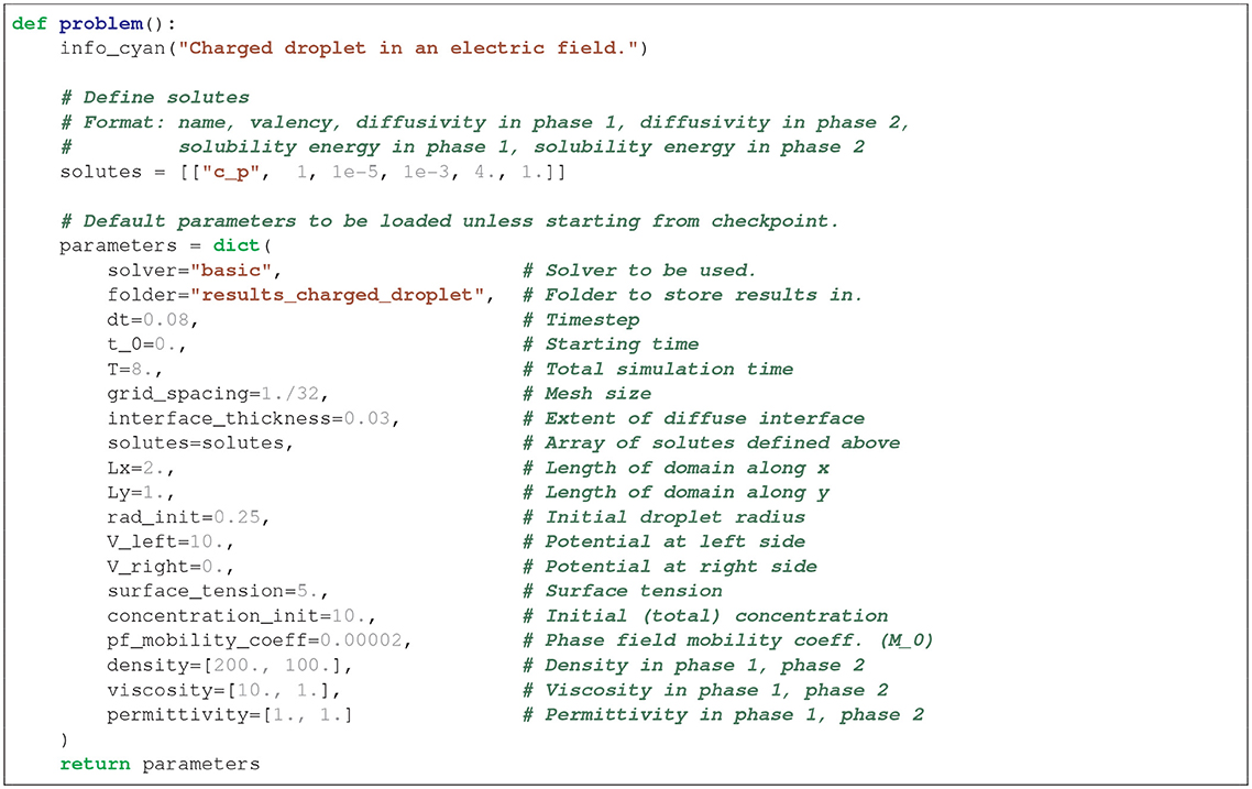
In Listing 1, we show an implementation of the problems function, which sets the necessary parameters that are required for the charged_droplet case to run. Here, the solutes array (which defines the solutes), contains only one species, but it can in principle contain arbitrarily many.
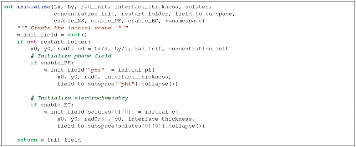
In Listing 2, we show the code for the initialization stage. Here, initial_pf and initial_c are functions defined locally inside the charged_droplet.py problem script, that set the initial distributions of the phase field and the concentration field, respectively. Here, it should be noted how the (boolean) parameters enable_PF, enable_EC and enable_NS allow to switch on or off either the phase field, the electrochemistry or the hydrodynamics, respectively.
4.3. The Solvers Submodule
Advanced users may develop solvers that can be placed in the solvers subdirectory. In the same way as with the problems submodule, a solver implementation constists of overloading a range of functions which are defined in solvers/__init__.py.
• get_subproblems: Returns a dictionary (dict) of the subproblems which the solver splits the problem into. This dictionary has points to the name of the fields and the elements (specified in problem) which the subspace is made up of.
• setup: Sets up the FEniCS solvers for each subproblem.
• solve: Defines the routines for solving the finite element problems, which are called at every time step.
• update: Defines the routines for assigning updated values to fields, which are called at the end of every time step.
The module solvers/basicnewton.py implements the monolithic scheme, while the module solvers/basic.py implements the segregated solver3. The problem is split up intothe subproblems corresponding to whether we have a monolothic or segragated solver in the function get_subproblems. Within the setup function, the variational forms are defined, and the solver routines are initialized. The latter are eventually called in the solve routine at every time step. Note that the element types are defined within the problem, and that the solvers in general can be applied for higher-order spatial accuracy without further ado. The task of get_subproblems is simply to link the subproblem to the element specification.
In Listing 3, we show how the get_subproblems function is implemented in the basic solver. As can be readily seen, the function formally splits the problem into the three subproblems NS, PF, and EC.
The other functions (such as setup) are somewhat more involved, but can be found at the Git repository [81].
Note that the implementations of the solvers presented above are sought to be short and humanly readable, and therefore quite straightforwardly implemented. There are several ways to improve the efficiency (and hence scalability) of a solver, at the cost of lost intuitiveness [43].
4.4. Boundary Conditions
Boundary conditions are among the few components of Bernaise which are implemented as classes. Physical boundary conditons may consist of a combination of Dirichlet and Neumann (or Robin) conditions, and the latter must be incorporated into the variational form. The boundary conditions are specified in the specific problem script, while the variational form is set up in the solver. To promote code reuse, keeping the physical boundary conditions accessible from the problems side, and simultaneously independent of the solver, the various boundary conditions are stored as classes in a separate module. The boundaries themselves should be set by the user within the problem. By importing various boundary condition classes from common/bcs.py, the boundary conditions can be inferred at user-specified boundaries.
Within the bcs module, the base class GenericBC is defined. The boolean member functions is_dbc and is_nbc specifies, respectively, whether the concrete boundary conditions impose a Dirichlet and Neumann condition, and both return false by default. The base class is inherited by various concrete boundary conditon classes, and by overloading these two member functions, the member functions dbc or nbc are, respectively called at appropriate times in the code. There is a hierarchy of boundary conditions which inherit from each other. Some of the boundary conditions currently implemented in Bernaise are:
• GenericBC: Base class for all boundary conditions.
- Fixed: Dirichlet condition, applicable for all fields.
* NoSlip: The no-slip condition—a pure Dirichlet condition with the value 0, applicable for velocity.
* Pressure: Constant pressure boundary condition—adds a Neumann condition to the velocity, i.e., a boundary term in the variational form.
- Charged: A charged boundary—a Neumann conditon intended for use with the electric potential V.
- Open: An open boundary—a Neumann condition is applied.
We note that when a no-flux condition is to be applied, no specific boundary condition class needs to be supplied, since the boundary term in the variational form then disappears (in particular when considering conservative PDEs).
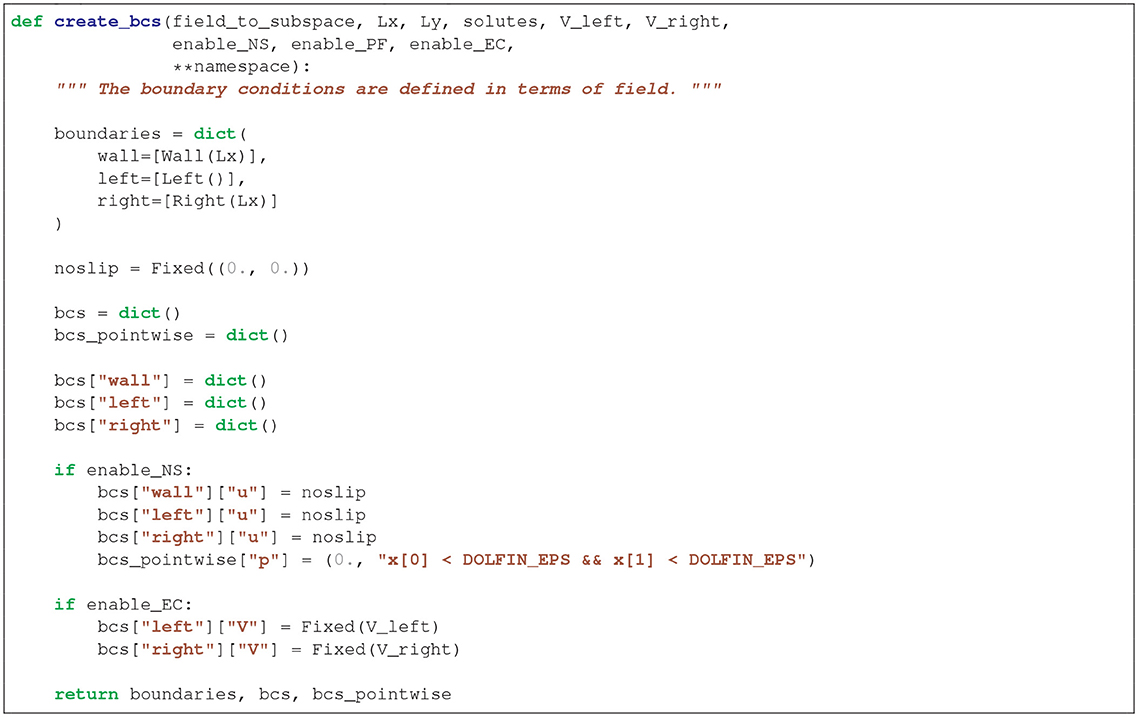
As an example, we show in Listing 4 the create_bcs function within the charged_droplet case. Here, the boundaries Wall, Left, etc., are defined in the standard FEniCS/DOLFIN way as instances of a SubDomain class.
4.5. Post-processing
An additional module provided in Bernaise is the post-processing module. It operates with methods analogously to how the main Bernaise script operates with problems. The base script postprocess.py pulls in the required method and analyses or operates on a specified folder. The methods are located in the folder analysis_scripts/ and new methods can be implemented by users by adding scripts to this folder.
To exemplify its usage, we consider a method to analyse the temporal development of the energy. This is done by navigating to the root folder and calling
» python postprocess.py method=energy_in_time folder=results_charged_droplet/1/
where we assume that the output of the simulation, we want to analyse, is found in the folder results_charged_droplet/1/. The analysis method energy_in_time above can, of course, be exchanged with another method of choice. A list of available methods can be produced by supplying the help argument from a terminal call:
» python postprocess.py -h
Similar to the problems submodule, the methods are implemented by overloading a set of routines, where default routines are found in analysis_scripts/__init__.py. The routines required to implement an analysis method are the following:
• description: routine called when a question mark is added to the end of the method name during a call from the terminal, meant to obtain a description of the method without having to inspect the code.
• method: the routine that performs the desired analysis.
The implementation hinges on the TimeSeries class (located in utilities/TimeSeries.py), which efficiently imports the XDMF/HDF5 data files and the parameter files produced by a Bernaise simulation. Several plotting routines are implemented in utilities/plot.py, and these are extensively used in various analysis methods.
5. Validation
With the aim of using Bernaise for quantitative purposes, it is essential to establish that the schemes presented in the above converges to the correct solution—in two senses:
• The numerical schemes should converge to the correct solution of the phase-field model.
• The solution of the phase-field model should converge to the correct sharp-interface equations4.
Unless otherwise stated, we mean by convergence that the error in all fields χ should behave like,
where ||·||h is an L2 norm, χ is the simulated field, χe is the exact solution, h is the mesh size, τ is the time step, kh is the order of spatial convergence, kτ is the order of temporal convergence (kτ = 1 in this work), and Ch and Cτ are constants.
In the following, we present convergence test in three cases. Firstly, in the limiting case of a stable bulk intrusion without electrochemistry, an analytical solution is available to test against. Secondly, using the method of manufactured solution, convergence of the full two-phase EHD problem to an augmented Taylor–Green vortex is shown. Thirdly, we show convergence toward a highly resolved reference solution for an electrically driven charged droplet.
We note that the aim of Bernaise is to solve coupled multi-physics problems, and while the solvers may contain subtle errors, they may be negligible for many applications, and dominant only in limiting cases. In addition to testing the whole, coupled multi-physics problem of two-phase EHD, a proper testing should also consider simplified settings where fewer physical mechanisms are involved simultaneously. A brief discussion of testing and such reduced models is given in Appendix C in Supplementary Material. In this section, we show the convergence of the schemes in a few relevant cases, which we believe represent the efficacy of our approach. Tests of simplified-physics problems are found in the Git repository [81].
5.1. Stable Bulk Intrusion
A case where an analytic solution is available, is the stable intrusion of one fluid into another, in the absence of electrolytes and electric fields. A schematic view of the initial set-up is shown in Figure 2. A constant velocity ( is the unit vector along the x axis) is applied at both the left and right sides of the reservoir, and periodic boundary conditions are imposed at the perpendicular direction. We shall here consider the convergence to the solution of the phase-field equation, i.e., retaining a finite interface thickness ϵ. This effectively one-dimensional problem is implemented in problems/intrusion_bulk.py.
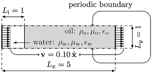
Figure 2. Schematic set-up of the stable bulk flow intrusion test case. Here, the “water” (subscript w) displaces the “oil” (subscript o). At the left and right boundaries, a constant velocity is prescribed.
Due to the Galilean invariance, we expect the velocity field to be uniformly equal to the inlet and outlet velocities, i.e., . The exact analytical solution for the phase field is given by
for which we shall consider the error norm. Note that the only parameters this analytical solution depends on are the initial position of the interface x0, the injection velocity v0, and the interface width ϵ. We consider the parameters ρ1 = ρ2 = 1000, μ1 = 100, μ2 = 1, σ = 2.45, ϵ = 0.03, , x0 = 1, Lx = 5, Ly = 1 and v0 = 0.1.
Figure 3 shows the convergence to the analytical solution with regards to temporal resolution. The order of convergence is consistent with the order of the scheme, indicating that the scheme is appreciable at least in the lack of electrostatic interactions.

Figure 3. Convergence in time for the case of stable intrusion. The mesh size is held fixed at h = 0.0039. (Left) We show the phase field interpolated at equidistant points along the centerline for increasing temporal resolution. The solid black line is the analytical solution. (Right) The integrated L2 norm of the phase field plotted against time step. The solid black line shows the theoretical convergence order of the scheme (~τ). As can be seen from the figure, it displays close to ideal scaling.
Figure 4 shows the convergence of the phase field with regards to the spatial resolution. The scheme is seen to converge at the theoretical rate, ~h2.

Figure 4. Convergence in space for the case of stable intrusion. The time step is held fixed at τ = 0.0025. (Left) Phase field interpolated at equidistant points along the centerline for increasing spatial resolution. (Right) The L2 norm of the phase field is plotted against mesh resolution. The solid black line shows the theoretical convergence order (~h2).
5.2. Method of Manufactured Solution: A Two-Phase Electrohydrodynamic Taylor–Green Vortex
Having established convergence in the practically one-dimensional case, we now consider a slightly more involved setting where we use the method of manufactured solution to obtain a quasi-analytical test case.
The Taylor–Green vortex is a standard benchmark problem in computational fluid dynamics because it stands out as one of the few cases where exact analytical solutions to the Navier–Stokes equations are available. However, in the case of two-phase electrohydrodynamics, the Navier–Stokes equations couple to both the electrochemical and the phase field subproblems. In Linga et al. (Submitted) the authors augmented the Taylor–Green vortex with electrohydrodynamics, and in this work we supplement the latter with a phase field and non-matching densities of the two phases.
We consider the full set of equations on the domain Ω = [0, 2π] × [0, 2π], where all quantities may differ in the two phases. The two ionic species have opposite valency ±z. The fields are given by
Here, the time-dependent coefficients are given by
where U0, C0 and Φ0 are scalars, and
where
Further, a bar indicates the arithmetic average over the value in the two phases, i.e., for any quantity χ, and is the arithmetic average over all diffusivities. The time-dependent boundary conditions are set by prescribing the reference solutions at the boundary of Ω for all fields given in (59a)–(59e), except the pressure p, which is set (to the reference value) only at the corner point (x, y) = (0, 0). The method of manufactured solution now consists in augmenting the conservation Equations (18), (19), (20) and (21) by appropriate source terms, such that the reference solution (59a)–(59e) solves the system exactly. These source terms were computed in Python using the Sympy package, and are rather involved algebraic expressions. The expressions are therefore omitted here, but can be found as a utility script in the Bernaise package. Note that in the special case of single-phase flow without electrodynamics, i.e., ϕ ≡ 1 and z = 0, we retrieve the classic Taylor–Green flow (with a passive tracer concentration field), where all artificial source terms vanish.
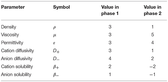
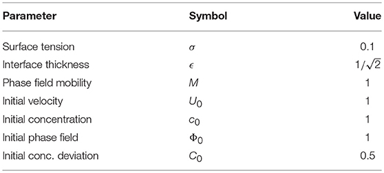
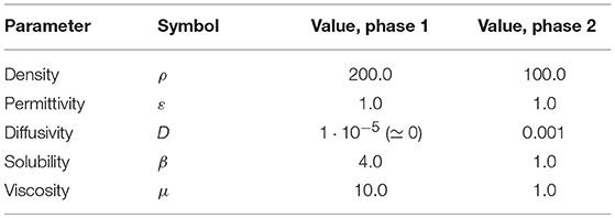
We consider now the convergence toward the manufactured solution. We let the grid size h ∈ [2π/256, 2π/16] and the time step τ ∈ [0.0001, 0.01], and evaluate the solution at the final time T = 0.1. The parameters for two phases used the simulation are given in Table 1, while the non-phase specific parameters are given in Table 2. Note that in order to test all parts of the implementation, all parameters are kept roughly in the same order of magnitude. When all the physical processes are included, the manufactured solution becomes an increasingly bad approximation and thus the resulting source terms become large. Thus, in order to avoid numerical instabilities, it was necessary to evaluate the error at a relatively short final time T. However, it should be enough to locate errors in most parts of the code.
We plot the L2 errors of all the fields as a function of the grid size h in Figure 5. In these simulations, we used a small time step τ = 0.0001 to rule out the contribution of time discretization to the error, cf. Equation (57). It is clear that the spatial convergence is close to ideal for all fields, indicating that the scheme approaches the correct solution. The pressure p displays slightly worse convergence and higher error norm than the other fields, which may be due to the pointwise way of enforcing the pressure boundary condition (all other fields have Dirichlet conditions on the entire boundary).
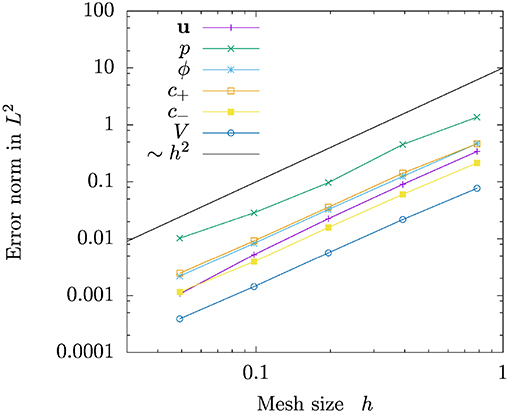
Figure 5. Convergence in space for the two-phase electrohydrodynamic Taylor–Green manufactured solution. The solid black line shows the theoretical convergence rate based on the order of the finite elements chosen (~h2). All fields display close to ideal convergence.
In Figure 6, we plot the L2 errors of the same fields as in Figure 5, but as a function of the time step τ. In the simulations plotted here, we used a fine grid resolution with h = 2π/256 to rule out the contribution of spatial discretization to the error, cf. Equation (57). Clearly, first order convergence is achieved for sufficient refinement, for all fields including the pressure.
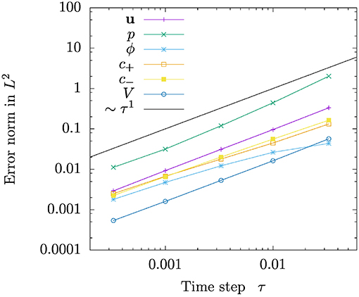
Figure 6. Convergence in time for the two-phase electrohydrodynamic Taylor–Green manufactured solution. The solid black line shows the theoretical convergence rate of the scheme (~τ1). All fields display close to ideal convergence.
5.3. Droplet Motion Driven by an Electric Field
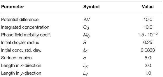
We now consider a charged droplet moving due to an imposed electric field; a problem for which there is no analytical solution available. However, by comparing to a highly resolved numerical solution, convergence for the fully coupled two-phase electrohydrodynamic problem can be verified. This problem has already been partly presented in the above, and is implemented in problems/charged_droplet.py. A sketch showing the initial state is shown in Figure 7. We consider an initially circular droplet, where a positive charge concentration is initiated as a Gaussian distribution, with variance , in the middle of the droplet. In this set-up, we consider only a single, positive species. The total amount of solute, i.e., integrated concentration, is . The left wall of the reservoir is kept at a positive potential, V = ΔV, while the right wall is grounded, V = 0. The top and bottom walls are assumed to be perfectly insulating, i.e., a no-flux condition is applied on concentration fields and electric fields, and a no-slip condition is applied on the velocity. The fluid surrounding the droplet is neutral, and its parameters are chosen such that the solute is only very weakly soluble in the surrounding fluid, and the diffusivity here is very low here to prevent leakage. The droplet is accelerated by the electric field toward the right, before it is slowed down due to viscous effects upon approaching the wall.
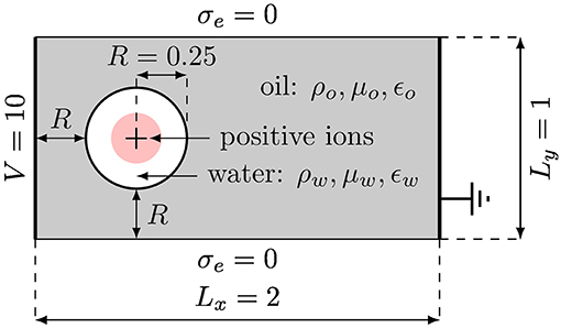
Figure 7. Schematic set-up of the test case of droplet motion driven by an electric field. The “water” droplet contains positive ions and is driven by the electric field set up between the high potential on the left wall and the grounded right wall.
With regard to reproducing the sharp-interface equations, we consider now the case of reducing the interface thickness ϵ → 0. To this end, we keep the ratio h/τ between mesh size and time step fixed, and further we keep the interface thickness ϵ proportional to h. The latter spans roughly 3–4 elements. Since the interface thickness ϵ changes, an important parameter in the phase-field model changes, which couples back to the equations, and thus the L2 norm does not necessarily constitute a proper convergence measure. We therefore resort to using the picture norm or contour of the droplet as a measure, i.e., the zero-level set of the phase field ϕ = 0. In particular, we will consider two observables: circumference and the center of mass (along x) of the droplet, as a function of resolution. A similar approach was taken for the case of phase-field models without electrodynamics by Aland and Voigt [66] who compared their benchmarks to sharp interface results by Hysing et al. [65].
The resolutions used in our simulations are given in Table 3. In order not to have to adjust the phase field mobility when refining, whilst still expecting to retrieve the sharp-interface model in the limit ϵ → 0, we choose the phase field mobility given by (33b). All parameters for the phasic quantities are given in Table 4, while the remaining parameters are given in Table 5. From these parameters, using the unit scaling adopted in this paper, we find an approximate Debye length (see section B2 in the Appendix for this expression), since we can approximate the order of magnitude of for a moderate screening.
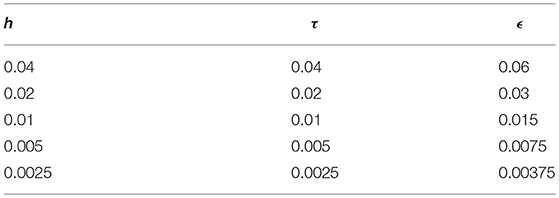
Table 3. Numerical parameters that vary with resolution in the charged droplet simulations: Mesh size h, time step τ, and interface thickness ϵ.
In Figure 8, we show the contour of the driven droplet at two time instances t = 4 and t = 8, and compare increasing resolution (simultaneously in space, time and interface thickness). Qualitatively inspecting the contours by eye, the droplet shapes seem to converge to a well defined shape with increasing resolution at both time instances.
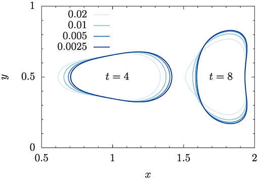
Figure 8. Shape comparison of electrically driven charged droplet at two time instances. The effect of the four resolutions given in Table 3 is shown. The legend shown in the figure refers to both spatial (h) and temporal resolution (τ).
However, qualitive comparison is clearly not enough to assess the convergence. As in Hysing et al. [66] and Aland and Voigt [65], we define three observables:
• Center of mass: We consider the center of mass of the dispersed phase (phase 2, i.e., ϕ < 0),
where we approximate the integral over the droplet (phase 2) by .
• Drift velocity: Similarly as above, the velocity at which the droplet is driven is measured by
• Circularity: Defined as the ratio of the circumference of the area-equivalent circle to the droplet circumference,
The circumference ℓ and the integrals are computed by the post-processing method geometry_in_time which is built into Bernaise.
Figure 9 shows the three quantities as a function of time for increasing resolution. (Here we have omitted the coarsest resolution h = 0.04 for visual clarity.) The curves seem to converge toward well-defined trajectories with resolution.
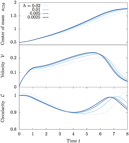
Figure 9. Observable quantities as a function of time. Increasing resolutions (spatial and temporal) are compared.
For a more quantitative comparison, we define the time-integrated error norm,
for a given quantity q. We can compute an empirical convergence rate of this norm,
for two successive resolutions (hi+1 > hi). Here we shall consider the L2 error norm in time, i.e., p = 2, and in practice we compute the integrals in time by cubic spline interpolation of measurement points saved at every 5 time steps. There is no exact solution, or reference high-resolution sharp-interface solution available for this set-up. However, if we now assume that the finest resolution is the exact solution, and use this as the reference field in Equation (68), we can compute error norms and convergence rates. These values are reported in Table 6.
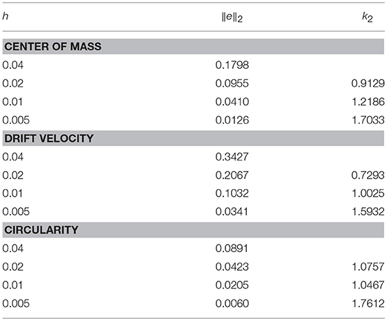
Table 6. Mesh size h, error norm ||e||2, and empirical convergence rate k2 for increasing grid refinement, assuming the solution for the finest resolution to be exact.
The computed convergence rates increase for all three observables and reach 1.6–1.7 with increasing resolution, indicating also quantitatively a convergence that is in agreement with the anticipated convergence rate. Considering Equation (57), from the temporal discretization, we expect k2 ≃ 1, and from the spatial k2 ≃ 2. Depending on which term contributes most to the error, we will measure either of these rates. The values measured here indicate that both terms may be comparable in magnitude; however if we instead of using directly the finest solution as reference, extrapolated the trajectories further, we would presumptively have achieved lower convergence rates. This might indicate that the convergence error is eventually dominated by the temporal discretization, cf. Equation (57).
6. Applications
6.1. Oil Expulsion From a Dead-End Pore
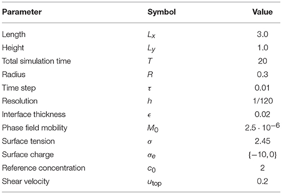
Here, we present a demonstration of the method in a potential geophysical application. We consider a shear flow of one phase (“water”) over a dead-end pore which is initially filled with a second phase (“oil”). The water phase contains initially a uniform concentration of positive and negative ions, c±|t = 0 = c0, and the water–oil interface is modeled to be impermeable. The simulation of the dead-end pore is carried out to preliminarily assess the hypothesis that electrowetting could be responsible for the increased expelling of oil in low-salinity enhanced oil recovery. The problem set-up is schematically shown in Figure 10. The phasic parameters used in the simulations are given in Table 7, and the remaining parameters are given in Table 8. This problem is implemented in the file problems/snoevsen.py.
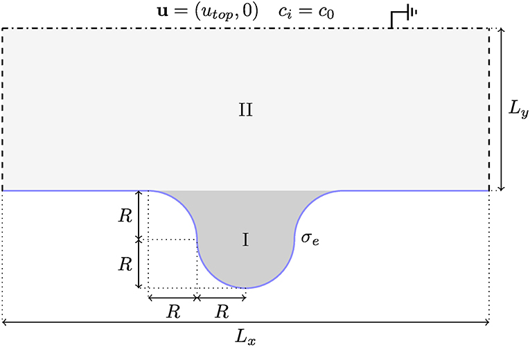
Figure 10. A schematic depiction of the “dead-end pore” geometry, with the appropriate boundary conditions for the problem and specified initial conditions for the phase field. The geometry is specified by the two lengths Lx, Ly, and the radius R used to define the dead-end pore in the center of the channel by a circle and a circular smoothed inlet. The roman numerals indicate the phase, along with the tone of gray. The darker phase is the oil-like phase (I), and the lighter one is the water-like phase (II).
To investigate the effect of including electrostatic interactions, we show in Figure 11 instantaneous snapshots of simulations with and without surface charge at different times. The left column, Figures 11A,C,E, shows the results for vanishing surface charge, and the right column, Figures 11B,D,F, shows the results for a surface charge of σe = −10.
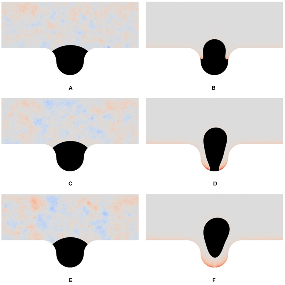
Figure 11. Oil released from a dead-end pore. We show instantaneous snapshots from the simulations of the dead-end pore under a shear flow. The black phase is the oil phase, which does not contain solutes, and the other phase is the water phase, which contains monovalent positive and negative ions. The color in the lighter phase indicates the local net charge, red meaning positive charge, blue negative charge, and gray neutral charge. The color scale is relative to the maximum deviation from neutral charge for an entire simulation; therefore the neutral simulations display numerical noise (which is of the order of machine precision). In the left column the surface charge is zero, and in the right column, a uniform surface charge density σe = −10 is set. The rows show snapshots at different times t. (A) t = 3.0, σe = 0. (B) t = 3.0, σe = -10. (C) t = 6.0, σe = 0. (D) t = 3.0, σe = -10. (E) t = 9.0, σe = 0. (F) t = 9.0, σe = -10.
For the uncharged case, the frames that are shown are almost indistinguishable. In fact, the main difference is the numerical noise of the total charge, which is due to roundoff errors of machine precision. The initial dynamics of the oil plug interface, which is to equilibrate with the neutral contact angle and the shear flow, mainly happens before the first frame presented; compare Figure 10 and Figure 11A.
A markedly different behavior is displayed in the right column, Figures 11B,D,F, where a uniform surface charge density is enforced at the walls at the simulation start, t = 0. Here, we see first that two tongues are intruding on both sides of the droplet, which push the droplet out into the center of the dead-end pore. The process is continued, as shown in the second frame, and finalized, as shown in the third frame, with the complete release of the droplet as the two tongues meet at the bottom of the dead-end pore, cutting the final contact point.
With these simulations, we have demonstrated the effects when a surface charge couples to hydrodynamics. This has lead to the observation that oil phase, on a larger scale than the Debye length, behaves like it is completely dewetting even when we locally enforce a neutral contact angle.
6.2. 3D Simulations of Droplet Coalescence and Breakup in an Electric Field
Finally, to demonstrate the ability of Bernaise to simulate 3D configurations, we present simulations of two oppositely charged droplets that coalesce. In order to achieve this efficiently, a fully iterative solver was implemented. The solver consists of a fractional step version of the basic solver, in the sense that within the fluid flow step, it splits between the velocity and pressure computations, as shown in Equations (56a), (56b), and (56c). The splitting introduces a weak compressibility which suffices to stabilize the problem [77] (with respect to the BB condition) and thus we can use P1 finite elements also for the velocity. The combination of fewer degrees of freedom and the applicability of iterative linear solvers imparts significant speed-up compared to coupled solvers, which is of paramount importance for 3D simulations. This yields advantages over solvers which rely on a mixed-element formulation of the hydrodynamic subproblem [70]. The detailed analysis of the fractional step solver will be published in a separate paper, but the implementation can be found in solvers/fracstep.py. For solving the linear systems iteratively, we use an algebraic multigrid (AMG) preconditioner and a generalized minimal residual (GMRES) linear solver for the electrochemical and the pressure correction step; Jacobi preconditioner (Jacobi) and a stabilized bi-conjugate gradient method (BiCGStab) for the velocity prediction, and Jacobi and GMRES for the velocity correction. For the phase field we use Jacobi and a conjugate gradient method.
To prevent leakage of ions out of the two coalescing droplets, a weighted geometric mean was used for the diffusivities:
instead of the arithmetic mean (25) used in most of the article.
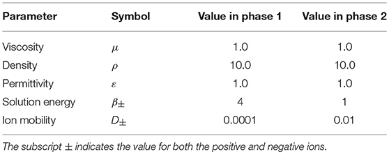
We consider a setup of two initially spherical droplets in a domain Ω = [0, Lx] × [0, Ly] × [0, Lz]. The droplets are centered at (Lx/2, Ly/2, (Lz±Lx)/2) and have a radius R. The lower droplet (along the z-axis) is initialized with a Gaussian concentration distribution of negative ions (z− = −1), whereas the upper droplet is initialized with positive ions (z+ = 1). The average concentration of the respective ion species within each droplet is c0, such that the total charge in the system is zero, and the initial spread (standard deviation) of the Gaussian distribution is R/3. A potential V0 is set on the top plane at z = Lz and the bottom plane at z = 0 is taken to be grounded. We assume no-slip and no-flux conditions on all boundaries, except for the electrostatic potential V at the top and bottom planes, and the fluid is taken to be in a quiescent state at the initial time t = 0. The phasic parameters used in the simulations are given in Table 9, and the remaining parameters are given in Table 10. The problem is implemented in the file problems/charged_droplets_3D.py.
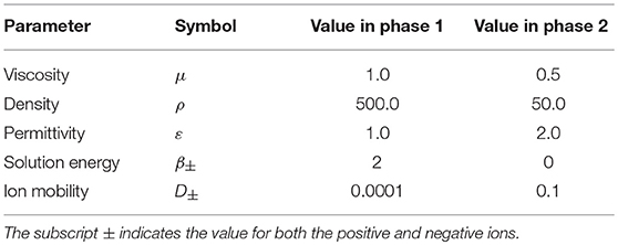
Table 9. Phasic parameters for the simulations of droplet coalescence and breakup in an electric field.
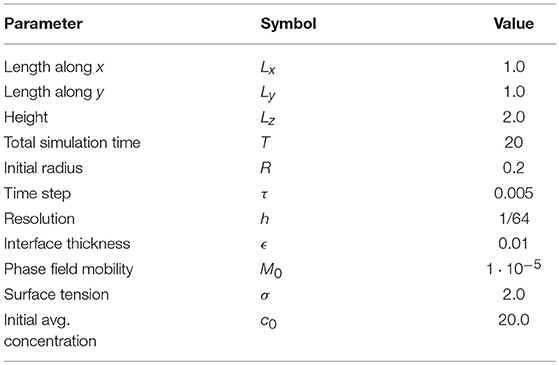
Table 10. Simulation parameters for the simulations of droplet coalescence and breakup in an electric field.
Figure 12 shows snapshots from the simulations at several instances of time. As seen from the figure, the droplets are set in motion toward each other by the electric field and collide with each other. Subsequently, the unified droplet is stretched, until it touches both electrodes. The middle part then breaks off, and as it is unstable, it further emits droplets that are released to two two sides. Finally, two spherical caps form at each electrode, and a neutral drop is left in the middle, due to the initial symmetry. Similar behavior has been observed in axisymmetric simulations (e.g.,[82]).
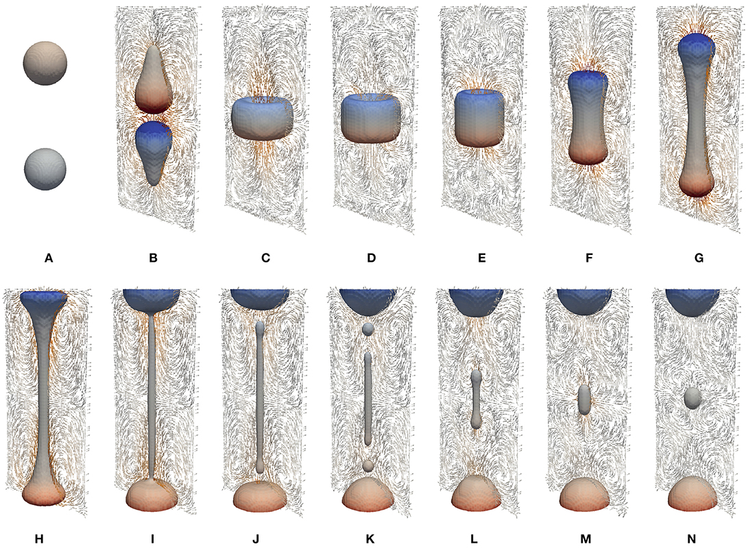
Figure 12. Snapshots from the simulations of droplet coalescence and subsequent breakup in an electric field. The phase boundary shows the ϕ = 0 isosurface of the phase field. The coloring indicates charge: red is positive and blue is negative. The color bar goes from -20 (deep blue) to 20 (deep red). The quivers show the velocity field in the x = 0.5 plane (color indicates intensity). (A) t = 0.0. (B) t = 0.25. (C) t = 0.5. (D) t = 0.75. (E) t = 1.0. (F) t = 1.25. (G) t = 1.5. (H) t = 1.75. (I) t = 2.0. (J) t = 2.25. (K) t = 2.5. (L) t = 2.75. (M) t = 3.0. (N) t = 4.0.
We finally carry out a strong scaling test of the linear iterative solver on a single in-house server with 80 dedicated cores. The results of average computational time per time step (averaged over 10 time steps) vs. number of cores are shown in Figure 13. We show here the amount of time spent per time step for all substeps in order to illuminate where most of the computational resources are spent. As can be seen, a significant portion of the computational time is spent on the electrochemical substep. Overall, the solver displays sublinear scaling with the number of cores, but the results are promising given that neither the solver nor the FEniCS install (a standard PPA install of FEniCS 2017.2.0 on Ubuntu 16.04 server) are fully optimized. Much could be gained by improving the two steps where solving a Poisson equation is involved; in particular it seems possible that more specifically tailored preconditioners than the straightforward AMG preconditioning could impart speedup. However, we stress that the division of labor between the steps is highly problem-dependent, and in particular, the electrochemical subproblem is susceptible to how far into the non-linear regime we are (see e.g., [45]).
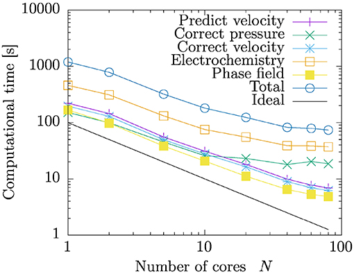
Figure 13. Strong scaling test. We show computational time per timestep vs. number of processor cores for the coalescence and breakup of droplets in 3D. The results are averaged over the 10 first timesteps for simulations with 128 × 128 × 256 = 4,194,304 degrees of freedom, with a time step τ = 0.02.
7. Discussion and Conclusion
We have in this work presented Bernaise, a flexible open-source framework for simulating two-phase electrohydrodynamics in complex geometries using a phase-field model. The solver is written in its entirety in Python, and is built on top of the FEniCS/DOLFIN framework [42, 83] for solving partial differential equations using the finite element method on unstructured meshes. FEniCS in turn interfaces to, e.g., scalable state-of-the art linear solvers through its PETSc backend [84]. We have proposed a linear operator-splitting scheme to solve the coupled non-linear equations of two-phase electrohydrodynamics. In contrast to solving the equations directly in a monolithic manner, the scheme sequentially solves the Cahn–Hilliard equation for the phase field describing the interface, the Poisson–Nernst–Planck equations for the electrochemistry (solute transport and electrostatics), and the Navier–Stokes equations for the hydrodynamics, at each time step. Implementation of new solvers and problems has been demonstrated through representative examples. Validation of the implementation was carried out by three means: (1) By comparison to analytic solutions in limiting cases where such are available, (2) by the method of manufactured solution through an augmented Taylor–Green vortex, and (3) through convergence to a highly resolved solution of a new two-phase electrohydrodynamics benchmark problem of an electrically driven droplet. Finally, we have presented applications of the framework in non-trivial settings. Firstly, to test the applicability of the code in a complicated geometry, and to illuminate the effects of dynamic electrowetting, we simulated a shear flow of water containing an electrolyte over a dead-end pore initially filled with oil. This problem is relevant from a geophysical standpoint, and exemplifies the potential of the method to simulate the dynamics of the interaction between two-phase flow and electric double layers. Secondly, the ability of the framework to simulate three-dimensional configurations was demonstrated using a fully iterative version of the operator-splitting scheme, by simulating the coalescence and subsequent breakup of two oppositely charged droplets in an electric field. The parallel scalability of the latter solver was tested on in-house computing facilities. The results presented herein underpin our aim that Bernaise can become a valuable tool both within the micro- and nanofluidics community and within geophysical simulation.
We have in this article not considered situations with multiple interacting droplets, complicated background flows, or complex mesh topologies. While the numerical procedure is capable of handling this, the main purpose of this article (in addition to presenting the software) has been to establish the validity of the approach, and to demonstrate its use through fairly rudimentary examples. Hence, we plan to use the present work as a basis for studying more complicated systems in the future.
There are several possible avenues for further development and use of Bernaise. With regard to computational effort, the linear operator-splitting scheme constitutes a major computational improvement over a corresponding monolithic scheme. For the resulting smaller and simpler subproblems, more specialized linear solvers and preconditioners can be used. However, the implementation of the schemes are still not fully optimized, as in many cases it is not strictly necessary to reassemble entire system matrices (multiple times) at every time step. Using ideas e.g., from Mortensen and Valen-Sendstad [43] on how to effectively preassemble system matrices in FEniCS, one could achieve an implementation that is to a larger extent dominated by the backend linear solvers. However, as the phase field is updated at every time step, there may be less to gain in performance than what was the case in the latter reference.
With regard to solving the Navier–Stokes equations, the solvers considered herein either rely on a coupled approach (the basic and basicnewton solvers) or a fractional step approach that splits between the computations of velocity and pressure (the fracstep solver that was considered in section 6.2). Using direct linear solvers, the coupled solvers yield accurate prediction of the pressure and can be expected to be more robust. However, direct solvers have numerical disadvantages when it comes to scalability, and Krylov solvers require specifically tailored preconditioners to achieve robust convergence. An avenue for further research is to refine the fracstep solver and develop decoupled energy-stable schemes for this problem, which seems possible by building on literature on similar systems [67–70, 75], Linga et al. (Submitted). The implementation of such enhanced schemes in Bernaise is straighforward, as demonstrated in this paper. On the other hand, in problems where interface forces and electric fields become sufficiently strong, and the equations become strongly nonlinearly coupled, it may be necessary to use a fully-implicit approach (along the lines of basicnewton), combined with direct linear solvers, to obtain a converged solution. In the future we aim to compare the ranges of applicability of various fully-implicit, semi-implicit, and splitting-based schemes for practical settings.
A clear enhancement of Bernaise would be adaptivity, both in time and space. Adaptivity in time should be implemented such that time step is variable and controlled by the globally largest propagation velocity (in any field), and a Courant number of choice. Adaptivity in space is presently only supported as a one-way operation. Adaptive mesh refinement is already used in the mesh initialization phase in many of the implemented problems. However, mesh coarsening has currently limited support in FEniCS and to the authors' knowledge there are no concrete plans of adding support for this. Hence, Bernaise lacks an adaptive mesh functionality, but this could be implemented in an ad hoc manner with some code restructuring.
In this article, we have not considered any direct dependence of the contact angle (i.e., the surface energies) on an applied electric field. However, the contact angle on scales below the Debye length is generally thought to be unaffected, albeit on scales larger than the insulator thickness, an apparent contact angle forms [85, 86]. Using the full two-phase electrohydrodynamic model presented herein, effective contact angle dependencies upon the zeta potential could be measured and used in simulations of more macroscopic models; i.e., models admissible on scales where the electrical double layers are not fully resolved [86]. This would result in a modified contact angle energy that would be enforced as a boundary condition in a phase field model [87].
Physically, several extensions of the model could be included in the simulation framework. Surfactants may influence the dynamics of droplets and interfaces, and could be included as in e.g., the model by Teigen et al. [88]. The model in its current form further assumes that we are concerned with dilute solutions (i.e., ideal gas law for the concentration), and hence more complicated electrochemistry could to some extent be incorporated into the chemical free energy α(c).
Finally, the requirement of the electrical double layer to be well-resolved constitutes the main constraint for upscaling of the current method. Thus, for simulation of two-phase electrohydrodynamic flow on larger scales, if ionic transport need not be accounted for, it would only require minor modifications of the code to run the somewhat simpler Taylor–Melcher leaky dielectric model, e.g., in the formulation by Lin et al. [60], within the current framework.
Author Contributions
AB, GL, and JM: designed the study; GL: developed the numerical scheme and methods; GL and AB: performed simulations; GL: wrote the first draft.
Funding
This project has received funding from the European Union's Horizon 2020 research and innovation program through a Marie Curie initial training networks under grant agreement no. 642976 (NanoHeal), and from the Villum Fonden through the grant Earth Patterns.
Conflict of Interest Statement
The authors declare that the research was conducted in the absence of any commercial or financial relationships that could be construed as a potential conflict of interest.
Supplementary Material
The Supplementary Material for this article can be found online at: https://www.frontiersin.org/articles/10.3389/fphy.2019.00021/full#supplementary-material
Footnotes
1. ^Instead of the full Navier–Stokes equations, which would be necessary in the presence of boundaries in the two in-plane dimensions.
2. ^The interpretation of this pressure depends on the formulation of the force on the right hand side of Equation (2).
3. ^The latter also contains an equilibrium solver for the quiescent electrochemistry problem, mainly to be used for initialization purposes.
4. ^Obviously, when the physical interface thickness may be resolved by the phase field, the sharp-interface assumption might be less sensible than the diffuse. Hence, in such cases this point might be too crude.
References
2. Mugele F, Baret JC. Electrowetting: from basics to applications. J Phys Condens Matter. (2005) 17:R705. doi: 10.1088/0953-8984/17/28/R01
3. Ristenpart W, Bird J, Belmonte A, Dollar F, Stone H. Non-coalescence of oppositely charged drops. Nature. (2009) 461:377–80. doi: 10.1038/nature08294
5. Squires TM, Quake SR. Microfluidics: fluid physics at the nanoliter scale. Rev Mod Phys. (2005) 77:977. doi: 10.1103/RevModPhys.77.977
6. Schoch RB, Han J, Renaud P. Transport phenomena in nanofluidics. Rev Mod Phys. (2008) 80:839. doi: 10.1103/RevModPhys.80.839
7. Mugele F, Duits M, Van den Ende D. Electrowetting: a versatile tool for drop manipulation, generation, and characterization. Adv Colloid Interface Sci. (2010) 161:115–23. doi: 10.1016/j.cis.2009.11.002
8. Nelson WC, Kim CJ. Droplet actuation by electrowetting-on-dielectric (EWOD): a review. J Adhes Sci Technol. (2012) 26:1747–71. doi: 10.1163/156856111X599562
9. Pollack M, Shenderov A, Fair R. Electrowetting-based actuation of droplets for integrated microfluidics. Lab Chip. (2002) 2:96–101. doi: 10.1039/b110474h
10. Srinivasan V, Pamula VK, Fair RB. An integrated digital microfluidic lab-on-a-chip for clinical diagnostics on human physiological fluids. Lab Chip. (2004) 4:310–5. doi: 10.1039/b403341h
11. Lee J, Kim CJ. Surface-tension-driven microactuation based on continuous electrowetting.J Microelectromech Syst. (2000) 9:171–80. doi: 10.1109/84.846697
12. Siria A, Bocquet ML, Bocquet L. New avenues for the large-scale harvesting of blue energy. Nat Rev Chem. (2017) 1:0091. doi: 10.1038/s41570-017-0091
13. Beni G, Hackwood S. Electro-wetting displays. Appl Phys Lett. (1981) 38:207–9. doi: 10.1063/1.92322
14. Beni G, Tenan M. Dynamics of electrowetting displays. J Appl Phys. (1981) 52:6011–5. doi: 10.1063/1.329822
15. Beni G, Hackwood S, Jackel J. Continuous electrowetting effect. Appl Phys Lett. (1982) 40:912–4. doi: 10.1063/1.92952
16. Hayes RA, Feenstra BJ. Video-speed electronic paper based on electrowetting. Nature. (2003) 425:383. doi: 10.1038/nature01988
17. Pride SR, Morgan F. Electrokinetic dissipation induced by seismic waves. Geophysics. (1991) 56:914–25. doi: 10.1190/1.1443125
18. Fiorentino EA, Toussaint R, Jouniaux L. Lattice Boltzmann modelling of streaming potentials: variations with salinity in monophasic conditions. Geophys J Int. (2016) 205:648–64. doi: 10.1093/gji/ggw041
19. Fiorentino EA, Toussaint R, Jouniaux L. Two-phase lattice Boltzmann modelling of streaming potentials: influence of the air-water interface on the electrokinetic coupling. Geophys J Int. (2016) 208:1139–56. doi: 10.1093/gji/ggw417
20. Hassenkam T, Pedersen CS, Dalby K, Austad T, Stipp SLS. Pore scale observation of low salinity effects on outcrop and oil reservoir sandstone. Colloids Surf A. (2011) 390:179–88. doi: 10.1016/j.colsurfa.2011.09.025
21. Hilner E, Andersson MP, Hassenkam T, Matthiesen J, Salino P, Stipp SLS. The effect of ionic strength on oil adhesion in sandstone–the search for the low salinity mechanism. Sci Rep. (2015) 5:9933. doi: 10.1038/srep09933
22. RezaeiDoust A, Puntervold T, Strand S, Austad T. Smart water as wettability modifier in carbonate and sandstone: a discussion of similarities/differences in the chemical mechanisms. Energy Fuels. (2009) 23:4479–85. doi: 10.1021/ef900185q
23. Pedersen N, Hassenkam T, Ceccato M, Dalby KN, Mogensen K, Stipp SLS. Low salinity effect at pore scale: probing wettability changes in Middle East limestone. Energy Fuels. (2016) 30:3768–75. doi: 10.1021/acs.energyfuels.5b02562
24. Plümper O, Botan A, Los C, Liu Y, Malthe-Sørenssen A, Jamtveit B. Fluid-driven metamorphism of the continental crust governed by nanoscale fluid flow. Nat Geosci. (2017) 10:685. doi: 10.1038/ngeo3009
25. De Gennes PG. Wetting: statics and dynamics. Rev Mod Phys. (1985) 57:827. doi: 10.1103/RevModPhys.57.827
26. Bonn D, Eggers J, Indekeu J, Meunier J, Rolley E. Wetting and spreading. Rev Mod Phys. (2009) 81:739. doi: 10.1103/RevModPhys.81.739
27. Snoeijer JH, Andreotti B. Moving contact lines: scales, regimes, and dynamical transitions. Ann Rev Fluid Mech. (2013) 45:269–92. doi: 10.1146/annurev-fluid-011212-140734
28. Melcher J, Taylor G. Electrohydrodynamics: a review of the role of interfacial shear stresses. Ann Rev Fluid Mech. (1969) 1:111–46. doi: 10.1146/annurev.fl.01.010169.000551
29. Saville DA. Electrohydrodynamics: the Taylor-Melcher leaky dielectric model. Ann Rev Fluid Mech. (1997) 29:27–64. doi: 10.1146/annurev.fluid.29.1.27
30. Fylladitakis ED, Theodoridis MP, Moronis AX. Review on the history, research, and applications of electrohydrodynamics. IEEE Trans Plasma Sci. (2014) 42:358–75. doi: 10.1109/TPS.2013.2297173
31. Taylor G. Studies in electrohydrodynamics. I. The circulation produced in a drop by electrical field. Proc R Soc Lond Ser A Math Phys Sci. (1966) 291:159–66.
32. Schnitzer O, Yariv E. The Taylor–Melcher leaky dielectric model as a macroscale electrokinetic description. J Fluid Mech. (2015) 773:1–33. doi: 10.1017/jfm.2015.242
33. Zholkovskij EK, Masliyah JH, Czarnecki J. An electrokinetic model of drop deformation in an electric field. J Fluid Mech. (2002) 472:1–27. doi: 10.1017/S0022112002001441
34. Monroe CW, Daikhin LI, Urbakh M, Kornyshev AA. Electrowetting with Electrolytes. Phys Rev Lett. (2006) 97:136102. doi: 10.1103/PhysRevLett.97.136102
35. Monroe CW, Daikhin LI, Urbakh M, Kornyshev AA. Principles of electrowetting with two immiscible electrolytic solutions. J Phys Condens Matter. (2006) 18:2837. doi: 10.1088/0953-8984/18/10/009
36. Yang Q, Li BQ, Ding Y. 3D phase field modeling of electrohydrodynamic multiphase flows. Int J Multiph Flow. (2013) 57:1–9. doi: 10.1016/j.ijmultiphaseflow.2013.06.006
37. Yang Q, Li BQ, Shao J, Ding Y. A phase field numerical study of 3D bubble rising in viscous fluids under an electric field. Int J Heat Mass Transf. (2014) 78:820–9. doi: 10.1016/j.ijheatmasstransfer.2014.07.039
38. Berry J, Davidson M, Harvie DJ. A multiphase electrokinetic flow model for electrolytes with liquid/liquid interfaces. J Comput Phys. (2013) 251:209–22. doi: 10.1016/j.jcp.2013.05.026
39. Zeng J. Non-linear electrohydrodynamics in microfluidic devices. Int J Mol Sci. (2011) 12:1633–49. doi: 10.3390/ijms12031633
40. Lu HW, Glasner K, Bertozzi A, Kim CJ. A diffuse-interface model for electrowetting drops in a Hele-Shaw cell. J Fluid Mech. (2007) 590:411–35. doi: 10.1017/S0022112007008154
41. Walker SW, Shapiro B, Nochetto RH. Electrowetting with contact line pinning: computational modeling and comparisons with experiments. Phys Fluids. (2009) 21:102103. doi: 10.1063/1.3254022
42. Logg A, Mardal KA, Wells G. Automated Solution of Differential Equations by the Finite Element Method: The FEniCS Book, Vol. 84. Springer Science & Business Media (2012).
43. Mortensen M, Valen-Sendstad K. Oasis: a high-level/high-performance open source Navier–Stokes solver. Comput Phys Commun. (2015) 188:177–88. doi: 10.1016/j.cpc.2014.10.026
44. Mitscha-Baude G, Buttinger-Kreuzhuber A, Tulzer G, Heitzinger C. Adaptive and iterative methods for simulations of nanopores with the PNP–Stokes equations. J Comput Phys. (2017) 338:452–76. doi: 10.1016/j.jcp.2017.02.072
45. Bolet A, Linga G, Mathiesen J. Electrohydrodynamic channeling effects in narrow fractures and pores. Phys Rev E. (2018) 97:043114. doi: 10.1103/PhysRevE.97.043114
46. Prosperetti A, Tryggvason G. Computational Methods for Multiphase Flow. New York, NY: Cambridge University Press (2009).
47. Yang C, Li D. A method of determining the thickness of liquid-liquid interfaces. Colloids Surf A. (1996) 113:51–9. doi: 10.1016/0927-7757(96)03544-3
48. Qian T, Wang XP, Sheng P. A variational approach to moving contact line hydrodynamics. J Fluid Mech. (2006) 564:333–60. doi: 10.1017/S0022112006001935
49. Qian T, Wang XP, Sheng P. Molecular scale contact line hydrodynamics of immiscible flows. Phys Rev E. (2003) 68:016306. doi: 10.1103/PhysRevE.68.016306
50. Sui Y, Ding H, Spelt PDM. Numerical simulations of flows with moving contact lines. Ann Rev Fluid Mech. (2014) 46:97–119. doi: 10.1146/annurev-fluid-010313-141338
51. Ervik Å, Lysgaard MO, Herdes C, Jimnez-Serratos G, Müller EA, Munkejord ST, et al. A multiscale method for simulating fluid interfaces covered with large molecules such as asphaltenes. J Comput Phys. (2016) 327:576–611. doi: 10.1016/j.jcp.2016.09.039
52. Walker SW, Shapiro B. Modeling the fluid dynamics of electrowetting on dielectric (EWOD). J Microelectromech Syst. (2006) 15:986–1000. doi: 10.1109/JMEMS.2006.878876
53. Teigen KE, Munkejord ST. Influence of surfactant on drop deformation in an electric field. Phys Fluids. (2010) 22:112104. doi: 10.1063/1.3504271
54. Tomar G, Gerlach D, Biswas G, Alleborn N, Sharma A, Durst F, et al. Two-phase electrohydrodynamic simulations using a volume-of-fluid approach. J Comput Phys. (2007) 227:1267–85. doi: 10.1016/j.jcp.2007.09.003
55. López-Herrera J, Popinet S, Herrada M. A charge-conservative approach for simulating electrohydrodynamic two-phase flows using volume-of-fluid. J Comput Phys. (2011) 230:1939–55. doi: 10.1016/j.jcp.2010.11.042
56. Anderson DM, McFadden GB, Wheeler AA. Diffuse-interface methods in fluid mechanics. Ann Rev Fluid Mech. (1998) 30:139–65. doi: 10.1146/annurev.fluid.30.1.139
57. Hohenberg PC, Halperin BI. Theory of dynamic critical phenomena. Rev Mod Phys. (1977) 49:435. doi: 10.1103/RevModPhys.49.435
58. Lowengrub J, Truskinovsky L The Royal Society. Quasi-incompressible Cahn–Hilliard fluids and topological transitions. Proc R Soc A. (1998) 454:2617–54. doi: 10.1098/rspa.1998.0273
59. Abels H, Garcke H, Grün G. Thermodynamically consistent, frame indifferent diffuse interface models for incompressible two-phase flows with different densities. Math Models Methods Appl Sci. (2012) 22:1150013. doi: 10.1142/S0218202511500138
60. Lin Y, Skjetne P, Carlson A. A phase field model for multiphase electro-hydrodynamic flow. Int J Multiphase Flow (2012) 45:1–11. doi: 10.1016/j.ijmultiphaseflow.2012.04.002
61. Campillo-Funollet E, Grün G, Klingbeil F. On modeling and simulation of electrokinetic phenomena in two-phase flow with general mass densities. SIAM J Appl Math. (2012) 72:1899–925. doi: 10.1137/120861333
62. Eck C, Fontelos M, Grün G, Klingbeil F, Vantzos O. On a phase-field model for electrowetting. Interf Free Boundaries. (2009) 11:259–90. doi: 10.4171/IFB/211
63. Nochetto RH, Salgado AJ, Walker SW. A diffuse interface model for electrowetting with moving contact lines. Math Models Methods Appl Sci. (2014) 24:67–111. doi: 10.1142/S0218202513500474
64. Grün G, Klingbeil F. Two-phase flow with mass density contrast: stable schemes for a thermodynamic consistent and frame-indifferent diffuse-interface model. J Comput Phys. (2014) 257:708–25. doi: 10.1016/j.jcp.2013.10.028
65. Hysing SR, Turek S, Kuzmin D, Parolini N, Burman E, Ganesan S, et al. Quantitative benchmark computations of two-dimensional bubble dynamics. Int J Numer Methods Fluids. (2009) 60:1259–88. doi: 10.1002/fld.1934
66. Aland S, Voigt A. Benchmark computations of diffuse interface models for two-dimensional bubble dynamics. Int J Numer Methods Fluids. (2012) 69:747–61. doi: 10.1002/fld.2611
67. Guillén-González F, Tierra G. Splitting schemes for a Navier–Stokes–Cahn–Hilliard model for two fluids with different densities. J Comp Math. (2014) 32:643–64. doi: 10.4208/jcm.1405-m4410
68. Grün G, Guillén-González F, Metzger S. On fully decoupled, convergent schemes for diffuse interface models for two-phase flow with general mass densities. Commun Comput Phys. (2016) 19:1473–502. doi: 10.4208/cicp.scpde14.39s
69. Metzger S. On numerical schemes for phase-field models for electrowetting with electrolyte solutions. Proc Appl Math Mech. (2015) 15:715–8. doi: 10.1002/pamm.201510346
70. Metzger S. On stable, dissipation reducing splitting schemes for two-phase flow of electrolyte solutions. In: Numerical Algorithms. (2018). p. 1–30. doi: 10.1007/s11075-018-0530-2
71. Nürnberg R, Tucker EJW. Stable finite element approximation of a Cahn–Hilliard–Stokes system coupled to an electric field. Eur J Appl Math. (2017) 28:470–98. doi: 10.1017/S0956792516000395
72. Langtangen HP, Logg A. Solving PDEs in Python. Berlin: Springer (2017). Available online at: https://link.springer.com/book/10.1007/978-3-319-52462-7
73. Nielsen CP, Bruus H. Concentration polarization, surface currents, and bulk advection in a microchannel. Phys Rev E. (2014) 90:043020. doi: 10.1103/PhysRevE.90.043020
74. Carlson A, Bellani G, Amberg G. Universality in dynamic wetting dominated by contact-line friction. Phys Rev E. (2012) 85:045302. doi: 10.1103/PhysRevE.85.045302
75. Shen J, Yang X. Decoupled, energy stable schemes for phase-field models of two-phase incompressible flows. SIAM J Numer Anal. (2015) 53:279–96. doi: 10.1137/140971154
76. Brenner SC, Scott LR. The Mathematical Theory of Finite Element Methods, Vol. 15. New York, NY: Springer Science and Business Media (2007).
77. Langtangen HP, Mardal KA, Winther R. Numerical methods for incompressible viscous flow. Adv Water Resour. (2002) 25:1125–46. doi: 10.1016/S0309-1708(02)00052-0
78. Chorin AJ. A numerical method for solving incompressible viscous flow problems. J Comput Phys. (1967) 2:12–26. doi: 10.1016/0021-9991(67)90037-X
79. Chorin AJ. Numerical solution of the Navier-Stokes equations. Math Comput. (1968) 22:745–62. doi: 10.1090/S0025-5718-1968-0242392-2
80. Guermond JL, Minev P, Shen J. An overview of projection methods for incompressible flows. Comput Methods Appl Mech Eng. (2006) 195:6011–45. doi: 10.1016/j.cma.2005.10.010
81. Linga G, Bolet A. Bernaise: Git repository. (2018). Available online at: https://www.github.com/gautelinga/BERNAISE
82. Pillai R, Berry J, Harvie D, Davidson M. Electrolytic drops in an electric field: a numerical study of drop deformation and breakup. Phys Rev E. (2015) 92:013007. doi: 10.1103/PhysRevE.92.013007
83. Logg A, Wells GN. DOLFIN: automated finite element computing. ACM Trans Math Softw. (2010) 37:20:1–20:28.
84. Balay S, Abhyankar S, Adams MF, Brown J, Brune P, Buschelman K, et al. PETSc Web page. (2017). Available online at: http://www.mcs.anl.gov/petsc
85. Mugele F, Buehrle J. Equilibrium drop surface profiles in electric fields. J Phys Condens Matter. (2007) 19:375112. doi: 10.1088/0953-8984/19/37/375112
86. Linga G, Bolet A, Mathiesen J. Controlling wetting with electrolytic solutions: phase-field simulations of a droplet-conductor system. Phys Rev E. (2018) 98:013101. doi: 10.1103/PhysRevE.98.013101
87. Huang JJ, Huang H, Wang X. Wetting boundary conditions in numerical simulation of binary fluids by using phase-field method: some comparative studies and new development. Int J Numer Methods Fluids. (2015) 77:123–58. doi: 10.1002/fld.3975
Keywords: electrokinectic, electrohydrodynamics (EHD), porous flow, phase field method, capillarity, numerical simulation, finite element method (FEM)
Citation: Linga G, Bolet A and Mathiesen J (2019) Bernaise: A Flexible Framework for Simulating Two-Phase Electrohydrodynamic Flows in Complex Domains. Front. Phys. 7:21. doi: 10.3389/fphy.2019.00021
Received: 26 October 2018; Accepted: 04 February 2019;
Published: 04 March 2019.
Edited by:
Alex Hansen, Norwegian University of Science and Technology, NorwayReviewed by:
Iver Hakon Brevik, Norwegian University of Science and Technology, NorwayChristian F. Klingenberg, Universität Würzburg, Germany
Copyright © 2019 Linga, Bolet and Mathiesen. This is an open-access article distributed under the terms of the Creative Commons Attribution License (CC BY). The use, distribution or reproduction in other forums is permitted, provided the original author(s) and the copyright owner(s) are credited and that the original publication in this journal is cited, in accordance with accepted academic practice. No use, distribution or reproduction is permitted which does not comply with these terms.
*Correspondence: Gaute Linga, bGluZ2FAbmJpLmRr
 Gaute Linga
 Asger Bolet
 Joachim Mathiesen
