 Ning Guo1
 Miguel Sangregorio
95% of researchers rate our articles as excellent or good
Learn more about the work of our research integrity team to safeguard the quality of each article we publish.
Find out more
ORIGINAL RESEARCH article
Front. Phys. , 14 January 2019
Sec. Low-Temperature Plasma Physics
Volume 6 - 2018 | https://doi.org/10.3389/fphy.2018.00145
This article is part of the Research Topic Plasma for Aerospace View all 6 articles
Additive manufacturing is rapidly opening its way into many areas of the aerospace industry, where different 3D printing technologies are finding niche applications in which they do not only simplify the process and allow shorter lead times, but also the particularities of these new fabrication methods yield new material properties that enhance the component and can lead to higher performance and longer service life of an aerospace system. Although rapid manufacturing processes are being tested for in-space manufacturing and are commonly used to fabricate UAV parts and some spacecraft subsystems with 3D printed components have been tested in space, little research has been conducted on the potential application of these techniques to electric thrusters. This paper presents the study conducted on the application of selective laser melting, a powder bed fusion technology, to the fabrication of ion engine grids and the challenges faced during the process. The first proof of concept and its optimization are described. Later, the development of the selective laser melting process for molybdenum, the study of the 3D printed materials' properties, their direct application to ion extraction systems, and the tests of additively-manufactured ion optics are described. It was found that 3D printed grids can be accurately fabricated with titanium and molybdenum, that they perform similar to conventional optics in short tests, that the selective laser melting process allows certain control of the coefficient of thermal expansion of the output and that this fabrication method allows the reproduction of sputtering erosion patterns. Future research in this direction will cover sputtering tests of selectively-laser-melted samples and the additive manufacturing of carbon-carbon grids.
Electric propulsion is a rapidly evolving field that encompasses several mature technologies that are progressively competing with chemical propulsion systems [1], such as ion thrusters and Hall thrusters [2], and that is spreading in new research directions, such as novel propellants [3, 4] and innovative concepts [5, 6].
Typically, electric thrusters have incorporated innovations related to materials and fabrication processes to their components. For instance, the development of carbon-based composite materials [7] boosted intense research that led to the development of carbon-carbon ion optics [8–10], which nowadays are one of the options for the extraction systems of ion thrusters [11, 12].However, very few works containing innovative fabrication approaches of electric propulsion components or focused on the application of new production technologies, such as additive manufacturing, have appeared recently.
Additive manufacturing encompasses a group of techniques that generate shapes by bringing material together through various physical processes, contrary to conventional machining methods, based on material removal. According to the ASTM F42 Committee on Additive Manufacturing standard [13], 3D printing technologies can be classified in different categories, depending on the type of feedstock and the method to turn it into solid parts: powder bed fusion, direct energy deposition, binder jetting, sheet lamination, material extrusion, material jetting, and vat photo-polymerization. Among them, powder bed fusion is the only one that is being used at an industrial level for metal and polymer fabrication. This category comprises two main technologies, electron beam melting (EBM) and selective laser melting (SLM), latter being the most widespread and intensively studied. SLM, a layer-wise material addition technique that allows the generation of three-dimensional shapes by selectively consolidating successive layers of powder material on top of each other by means of the energy supplied by a computer-controlled laser beam [14], has already generated parts of UAVs [15, 16], rocket engines [17] and cubesat components [18, 19].
Electric propulsion can also benefit from the advantages of SLM, as shown by Romei et al. [20], when they selectively laser melted a stainless-steel resistojet heat exchanger. However, one of the big challenges for the application of SLM to the fabrication of electric thrusters' components is the development of new materials for this process. While steel, titanium and aluminum parts are selectively laser melted for different industries [21, 22], metals like molybdenum, which is an option for ion engine components such as ion optics, hollow cathode keepers and Hall thruster anodes [23], have not been fabricated through this method.
This research introduces SLM as a manufacturing method for electrostatic thrusters' components. Due to the relatively high complexity and high precision requirements of ion thrusters' extraction systems, it was decided to focus the study on the development of this component. In the first place, a proof of concept of additively-manufactured ion optics (AMIO) was produced and optimized to meet precision requirements. Then, the SLM process for molybdenum and different combinations of molybdenum and titanium were studied in order to find the right fabrication parameters. After that, the thermal and mechanical properties of the 3D printed metals were analyzed and compared with those of solid (non-porous) metals in order to understand their potential beneficial application for ion optics. Finally, titanium and molybdenum AMIO of different sizes were installed on ion sources and tested for a short time.
Despite the fact that molybdenum is the traditional material for ion optics, other metals with low sputtering erosion rate and good thermal (low coefficient of thermal expansion) and structural properties have been used for ion engine grids, specifically, titanium [24, 25]. Given that SLM fabrication of titanium alloys have been thoroughly investigated due to their many applications to the aerospace and medical industries, Ti6Al4V was chosen as the material for this proof of concept.
Several 14 cm diameter, 0.4 mm thick flat screen grids were fabricated with a SLM machine from a Chinese manufacturer, Farsoon Technologies, model FS271M, which incorporates a IPG 500W Yb-fiber laser that provides a spot diameter of 0.1 mm and reaches a scanning speed of 15 m/s, is designed with unidirectional powder feed mode that allows adjustable layer thickness between 0.02 and 0.5 mm through a ceramic blade, and whose maximum guaranteed volume build rate is 20 ml/h. The whole fabrication process, including material and equipment preparation, machine parameter selection, part generation, heat treatment, part/build platform separation and postprocessing, took 23 h and required one operator to follow its progress.
Figure 1A illustrates the SLM process: a powder-spreading blade spreads a layer of powder on the fabrication piston and then a laser scans the powder following the design pattern. Once the first layer is completed, the powder delivery piston moves upwards and the fabrication piston moves downwards the same distance. Then the blade spreads the next layer of powder over the previous one, which will act as a powder bed, and the laser scans it following the pattern of the correspondent layer of the design. This process, which takes place in inert atmosphere, continues until the component has been completed. Figure 1B shows the first stage of the part/build platform separation process. The grid, attached to a titanium build platform on which it was generated, was removed from the SLM machine. The build platform was then clamped so that it remained fixed while a fast-moving nickel wire cut the grid off. The stresses generated in the wire cutting process led to the warping of the optic, which was solved by sandwiching the grid between two heated flat plates.
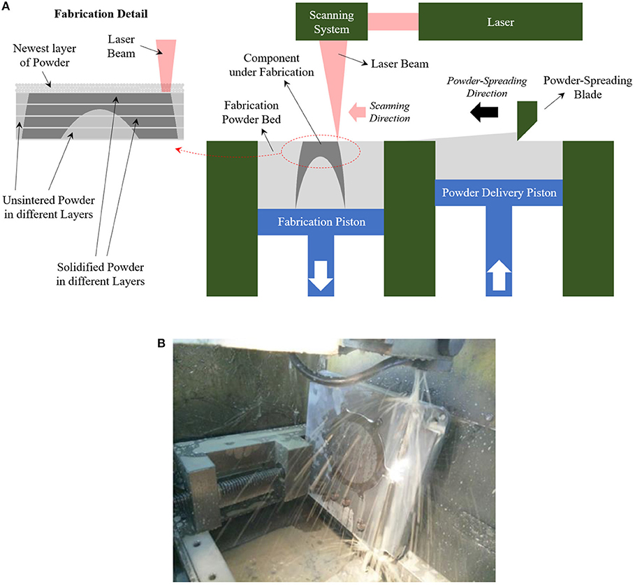
Figure 1. (A) Illustration of the SLM process and (B) Beginning of build platform/grid separation process.
The results presented a smooth surface on both sides, comparable to the finishing achieved through conventional fabrication methods, although it is being investigated how high-quality surface finishing can be guaranteed in every fabrication. This problem should be addressed independently for the lower surface, defined as the surface in touch with the build platform during the fabrication process, and the upper surface, which is the last layer to be built by the SLM machine. The wire cutting process could leave marks on the lower surface, which can be removed by sand blasting, which would simultaneously polish other irregularities. Additionally, the grid could be placed again on another build platform and be scanned again by the machine so that its surface finish would coincide with that of the upper surface. The few irregularities on this surface could be removed by sand blasting.
The initial dimensional accuracy of the hole array positioning (40 μm) didn't meet design requirements, so an optimization process was conducted. It involved dimensional accuracy testers (see Figure 2), that is, trapezoidal samples with nine holes with the geometric characteristics of the hole array of the grid. As shown in Figure 2, the energy density applied during successive SLM fabrication processes was increased until 120 Jmm−3. The blue line shows a quadratic fitting of the experimental data. The SLM machine proved to be able to guarantee tolerances under 20 μm, enough for typical aperture positioning [26].
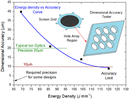
Figure 2. Optimization process of the grid's hole array dimensional accuracy.
The main advantages of AMIO with respect to traditional ion engine grids are the comparatively fast production process and the flexibility of this process, as the same equipment can produce optics of different sizes, shapes, and materials. Additionally, nesting different grids of several shapes on one build platform can simultaneously fabricate optics that would be manufactured separately through traditional methods. Thus, AMIO would decrease the cost per part as compared to traditional manufacturing methods.
After SLM proved to be a feasible method to fabricate ion optics, the next step was to use molybdenum. However, no study or application of molybdenum or other high melting point metals could be found in the available literature, so it was necessary to conduct a SLM parametric study in order to develop the SLM fabrication process with molybdenum.
A SLM process has roughly four fabrication parameters that can be adjusted: laser power P (W), scanning speed v (mm s−1), hatch spacing h (mm), that is, the distance between two consecutive laser beam paths that scan one layer of material, and layer thickness t (mm). These parameters can be combined in a magnitude called energy density ED (J mm−3) [27, 28], a show in Equation 1, which represents the energy provided to the raw material by the laser per volume unit.
The aim of a SLM parameter study is to find the right parameter combination to fabricate parts with a new material. The result of the study will be the energy density, or a range of energy densities, that produce the desired outputs, which is a characteristic value for each material. Despite the fact that the four fabrication parameters (P, v, h, and t) have the same weight in the ED formula, most of parametric studies focus on the variation of laser power and scanning speed, setting hatch spacing and layer thickness close to minimum machine values. This is especially true for high melting point metals, such as molybdenum (melting point 2900°C, approximately), where high energy densities have to applied in order to generate a melt pool that will solidify yielding mechanical properties similar to those achieved by conventional manufacturing methods.
Figure 3 shows the summary of the conducted parametric study. It started by applying energy density values <100 J mm−3, which resulted in fabrication failure, as the energy supplied was not enough to melt powder boundaries. Molybdenum sinterization was achieved with energy densities in the neighborhood of 150 J mm−3. ED was increased progressively until the results presented a smooth surface and the porosity was reduced to values under 10%, which happened for ED close to 300 J mm−3. In order to reduce porosity, these energy densities were increased to values close to the maximum achievable by the SLM machine, but the samples were burned due to the excess of energy. It was concluded that molybdenum parts can be satisfactorily fabricated by SLM providing energy densities in the neighborhood of 300 J mm−3. As a reference, fabrication values for titanium (melting point 1900°C, approximately) are around ED = 100 J mm−3. In order to ensure the repeatability of the fabrication process, a batch of samples was printed for every parameter combination.
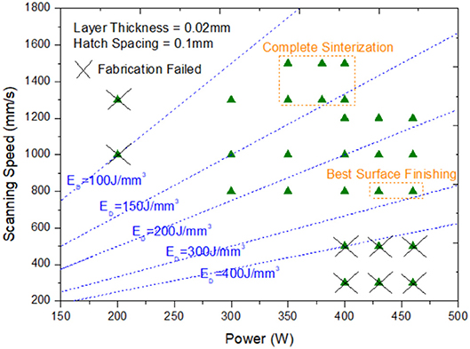
Figure 3. Parametric study of the SLM process of molybdenum.
Once the right parameter combination was found, several batches of small ion optics (4 cm diameter) set were fabricated. Figure 4A shows a build platform after it was removed from the SLM machine and when the excess powder had been partially removed. Given the small size of the optics, it was possible to allocate several sets on one build platform, and also some samples, whose function was to contrast the surface quality with that of the grids and check if the parameters that yielded acceptable parallelepipeds were able to properly generate ion optics. Figure 4B shows a set of screen and accelerator grids after the wire cutting.
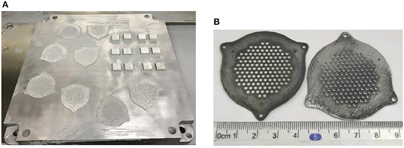
Figure 4. (A) ion optics and samples attached to build platform and (B) a grids' set after wire cutting.
Contrary to what happened during the build platform/part separation of the 14 cm diameter grid, smaller optics did not warp after the wire cutting process, which, alongside the fact that the smaller size of the optic allows the simultaneous fabrication of several screen and accelerator grids set, resulted in a shorter manufacturing time (four molybdenum grids' sets in ~15 h).
Similar to what happened in fabrications with titanium, surface finishing was comparable to that of traditional manufacturing processes for some grids, but could not be guaranteed for all the components, so it is one of the main points under investigation.
Samples of several combinations of molybdenum and titanium were selectively laser melted with different energy densities, and their densities and coefficients of thermal expansion (CTE) measured and plotted, as shown in Figure 5A. It can be seen that, the higher the energy density, the closer the CTE and the density of the SLM materials get to the values of the pure metals, that is, density increase and CTE decreases as energy density grows. It was found that CTE changes with the variation of energy density were more noticeable (up to 20%) than for the density (<10%).
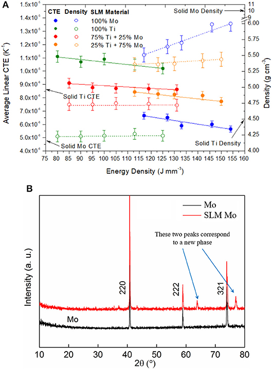
Figure 5. (A) Average linear CTE and density of samples fabricated with different energy densities and (B) X-Ray Diffraction analysis of a SLM Mo sample compared with typical Mo.
X-Ray Diffraction analysis was conducted on pure molybdenum samples and SLM molybdenum samples (100% Mo case), as shown in Figure 5B. The two additional peaks of the spectrum revealed that a new phase resulted from the fabrication process, which accounts for the different thermal behavior. Currently, the same analysis is being applied to several SLM samples in order to compare their spectrums with those of pure metals or traditionally fabricated alloys.
Given that the CTE of the output of a SLM fabrication can be controlled by the energy density supplied during the process, the concept of an ion optics set with different CTE for screen and accelerator (accel) grid was proposed. In typical extraction systems, given that the temperature of the screen grid is higher [29], it will expand more than accel grid, reducing the grid-to-grid gap, which will influence the perveance of the extraction system. However, if the CTE of the accel grid was higher than that of screen grid, then both grids could expand more similarly, thus reducing the difference between cold and hot gap. This concept is illustrated in Figure 6, where the upper part represents the thermal behavior of a two-grid ion acceleration system with the same CTE for screen and accel grids and, the lower part, that of the same grids' set when accel grid has a CTE higher than screen grid.
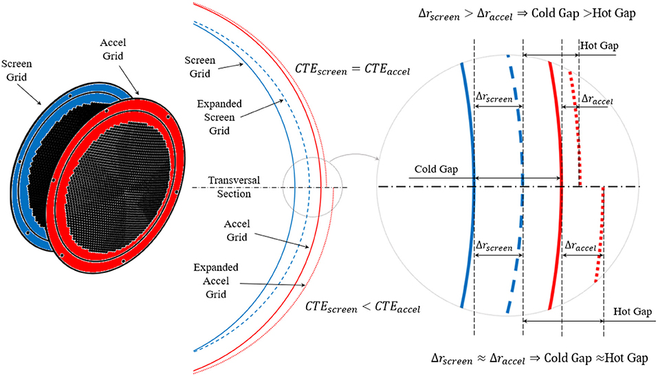
Figure 6. Representation of the grid-to-grid gap change for ion optics when screen grid and accel grid have the same CTE (upper part) and when the CTE of accel grid is higher than screen grid's (lower part).
Ion optics systems with different CTEs for screen and accel grids can have an additional benefit. While in typical extraction systems unequal expansion of grids causes aperture center misalignment, which distorts ion trajectories, when accel and screen grids expand similarly this problem can be mitigated.
Thermal expansion of ion optics was simulated by Shunk [30] and studied theoretically by Soulas [31], who developed a theoretical model to predict the normal (w) and tangential (v) displacements of perforated spherical shells. By applying a similar model to a two-grid set of 50 cm diameter domed extraction system with circular apertures distributed in a hexagonal hole array, where screen grid is 1.6 mm thick and has 0.84 mm diameter apertures and accel grid is 4.1 mm thick and has 0.4 mm diameter apertures, normal and tangential displacements can be calculated for the two grids. Figure 7 shows the normal and tangential displacements of these grid set under typical axisymmetric thermal load during operation. Figure 7 also presents the displacements of a conceptual set of AMIO with the same geometry in which the CTE of accel grid is 20% higher than screen grid's.
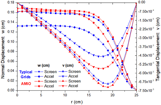
Figure 7. Normal and tangential displacements for typical ion optics and for AMIO.
Figure 8 shows the computation of the grid-to-grid gap change, that is, the difference between the expansion of accel and screen grid. The negative values imply that the gap between the optics decreases during operation. Aperture misalignment for typical grids and AMIO is also computed by subtracting the tangential displacement of screen grid to that of accel grid. It can be seen that AMIO offers a better solution in terms of grid-to-grid gap change (average reduction of 65%) and aperture misalignment (average reduction of 38%) than traditional ion optics.
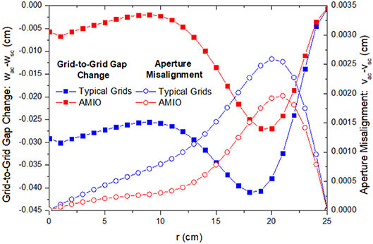
Figure 8. Grid-to-grid gap and aperture misalignment for typical ion optics and for AMIO.
A Ti6Al4V screen grid and one molybdenum ion optics' set were installed on real ion sources that were ignited. It was intended to run short tests in order to find operation anomalies or early deterioration signs of the additively-manufactured extraction systems.
An ion source was designed to be tested with the Ti6Al4V grid. The goal of this experiment was to investigate the potential problems of installing a 3D printed grid on an ion source, such as non-uniform material properties that cause deformation of the surface on the screw tightening regions, or early erosion defects on the high-density plasma regions due to porous superficial layers of the grid undetected during postproduction inspection, and measure the discharge curve of the ion source x10−2 T.
A simple stainless-steel discharge chamber with ceramic insulations was designed and fabricated. Figures 9A,B show, respectively, an open isometric view and a rear view of the chamber with its different parts numbered: (1) chamber cylinder, (2) cylinder rear plate, attached to the inside part of the chamber cylinder, (3) ceramic hollow cathode keeper insulator, that electrically separates the chamber from the hollow cathode (4) xenon feed system, (5) ceramic grid insulation ring, which electrically separates the chamber and the grid and (6) ceramic bolts' insulator, which insulate the bolts that attach the grid to the discharge chamber, and (7) the Cobalt-Samarium magnet rings that provide the magnetic field to contain the plasma, shown in Figure 9C, where the color bar represents the strength of the magnetic field produced by the rings and the black lines are the magnetic field lines.
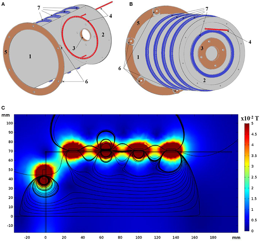
Figure 9. Discharge chamber (A) front open isometric view, (B) rear view, and (C) magnetic field.
Figure 10A shows the ion source assembly inside the vacuum chamber where it was tested, Figure 10B shows the ignition at the beginning of the experiment, and Figure 10C shows the discharge curve measured at the end of the ion source, which fits a typical discharge process [32]. The ion source with the 3D printed grid was ignited and operated shortly. After the test, the screen grid was removed and inspected for early erosion signs, but it did not present any.
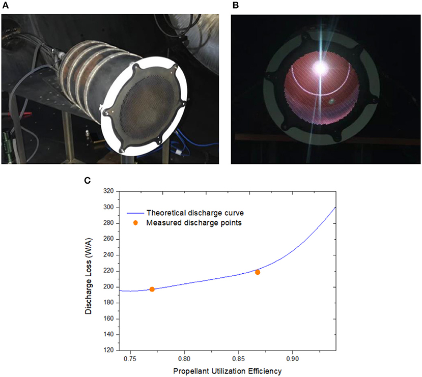
Figure 10. (A) Ion source and screen grid assembly, (B) ion source ignition, and (C) ion source discharge curve.
A set of 3D printed molybdenum screen and accelerator ion optics were tested on a helicon ion thruster. The two grids were installed as a replacement for optics fabricated through conventional methods and a short test was successfully conducted with the additively-manufactured extraction system.
Figure 11 shows a diagram of the helicon ion thruster system used in this test, including the electric connections of the extraction system. It is a small-dimension laboratory scale assembly that can be operated both with and without ion optics. The Argon source is connected to a discharge tube, where it injects gas that is later ionized by means of the radiofrequency source and the magnetic coil. The discharge tube ends in a cylindric vacuum tank (32 cm diameter × 50 cm height) with apertures through which an acceleration system can be installed. Figure 12A presents the plasma extraction system with the electrical connections before it was installed at the end of the discharge tube.
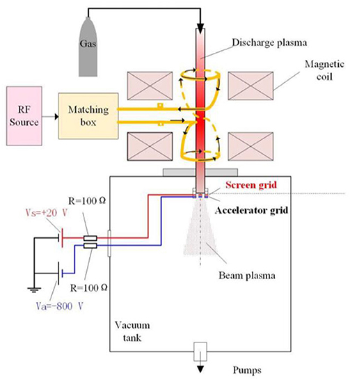
Figure 11. Helicon ion thruster system diagram.
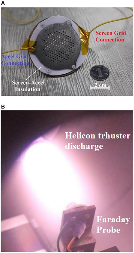
Figure 12. 3D printed molybdenum extraction system assembly (A) before installation on the thruster and (B) during operation.
The test was conducted with a background pressure of 5 × 10⁻²Pa and a centerline magnetic field of 200G. The radiofrequency source power was 1 kW, the Argon mass flow rate was set to 10.8 sccm and the gas pressure during the test was 0.4 Pa. Figure 12B shows the operation of the engine with the acceleration system.
Figure 13A shows screen and Accel grids' voltages and currents during the helicon thruster test. Electric potential was increased with the time during the experiment, keeping accel grid's voltage one or two orders of magnitude higher than that of screen grid. As for the current, it was increased with the time for screen grid and decreased for accel grid, with higher current values applied to screen grid. Figure 13B shows currents vs. voltages for screen and accel grids during the helicon thruster test. Whereas, screen grid's electric potential and current variations with time were the same for the three times that the experiment was conducted, three different current variations were applied to the accel grid.
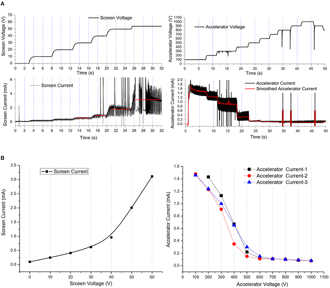
Figure 13. (A) Screen and Accel grids' voltages and currents during the helicon thruster test and (B) currents vs. voltages for screen and accel grids during the helicon thruster test.
The helicon ion thruster was operated for several hours, during which the accelerator grid potential was adjusted several times. The 3D printed extraction system worked normally and did not present any operation anomaly. After the experiment, the ion optics were removed and inspected, but no early deterioration signs were found.
Another test was conducted with a set of optics whose surface quality was not optimal, which resulted in the generation of electric arcs between screen and accel grid after ignition. This fact supported the idea that it is essential to be able to guarantee good surface finishing for every grid.
The work presented in this article is a summary of an ongoing project at the Beijing Institute of Technology to develop additively-manufactured ion optics (AMIO), whose outline is shown on Figure 14, in which completed phases and those on an advanced stage of development have been squared in red. The study on the CTE of selectively laser melted materials will continue, and it is intended to build and test different-CTE domed grids. In order to verify the suitability of SLM for the fabrication of ion optics, the sputtering behavior of selectively laser melted metals have to be assessed. Additionally, the additive manufacturing of carbon-based materials has been unsuccessfully attempted and different ways to obtain successful prototypes are being explored. The ultimate goal of the project would be to obtain extraction systems with properties similar to carbon-carbon (CC) grids through additive manufacturing.
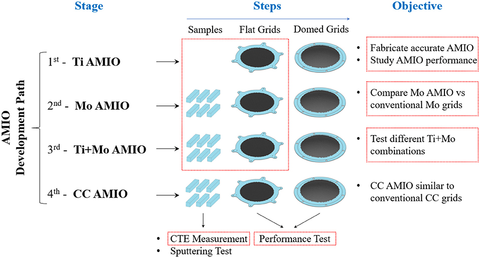
Figure 14. AMIO development path.
Apart from AMIO's development, the research presented in the previous sections is currently expanding in several directions. Currently, the SLM fabrication of other electric thrusters' components, such as Hall thrusters' anodes, is being investigated and the development of the SLM process for other refractory materials used in electric propulsion, such as tantalum, is being considered. Additionally, the reproduction of sputtered structures through SLM is being investigated. SLM can generate ion optics with the “pits and trenches” patterns after a certain operation period predicted by a PIC model, as shown in Figure 15. These grids could be tested to understand ion thruster performance change with an eroded extraction system and to measure plume performance, which is considered constant in current PIC models. These results can help enhance PIC models and shorten ion optics' life tests.
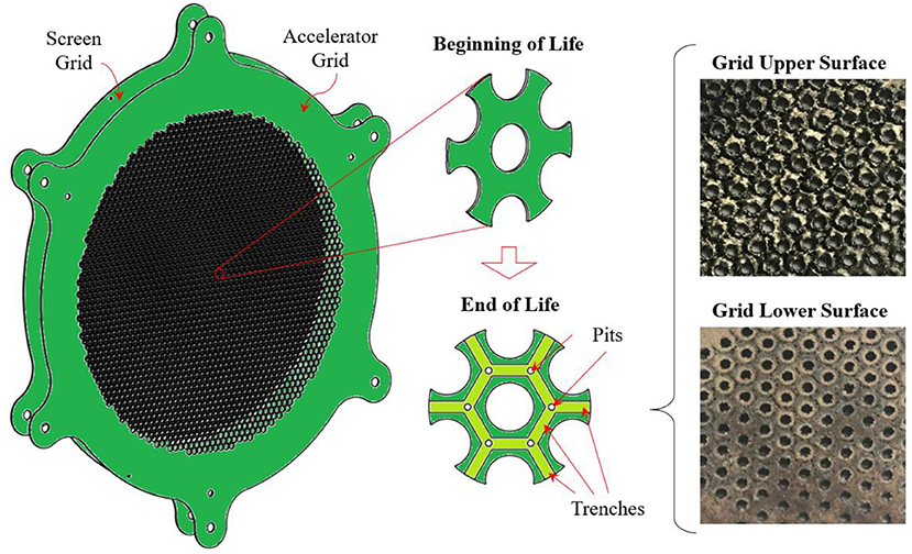
Figure 15. Ion optics erosion pattern and the pattern exhibited by the unsuccessfully formed grids.
This work has presented the progress in the research of additively manufactured ion optics (AMIO), which aims to produce healthy components for research and commercial applications and to set the foundations to explore the in-space manufacturing of electric propulsion parts through additive manufacturing technologies. So far, it has been shown that, regarding microstructure, surface finishing and dimensional accuracy, it is feasible to use SLM fabricate ion optics, both with titanium and molybdenum. A parametric study showed that high energy density values (300 J mm−3) are required to print the refractory metal, molybdenum. AMIO are not only competitive from the manufacturing time and cost points of view, which make them attractive for commercial use, but the control of the CTE of the grids through the energy density supplied during the SLM process may allow the mitigation of typical metallic ion optics thermal expansion problems. Additionally, short tests on real ion sources were successfully conducted with 3D printed grids and it was shown that it is possible to selectively-laser-melt grids with sputtering erosion patterns.
The results of this research are applicable to other electrostatic thrusters' parts, such as Hall thruster anodes, and can set the base for other studies involving the SLM process of refractory metals. In further stages, the sputtering behavior of selective laser melted molybdenum will be studied and the SLM process for carbon-based materials will be developed. It is also intended to conduct longer tests of 3D printed components installed on ion sources and to reproduce sputtered structures through SLM.
The work presented in this article contains the latest results of the Ph.D research of MS, who was supervised by KX and NW. ZZ and SG made contributions related to the evaluation of results. NG in charge of of the design of the grids featured in this study and of the supervision of the tests conducted on them.
This work was supported by the National Natural Science Foundation of China under Grant Nos. 11402025 and 11475019. We would also like to acknowledge the financial support from the National Key Laboratory of Science and Technology on Vacuum Technology & Physics under Grant No. ZWK1608.
The authors declare that the research was conducted in the absence of any commercial or financial relationships that could be construed as a potential conflict of interest.
The authors would like to thank Professor Francesco Taccogna for the insights he offered during the discussion about the 3D printing of ion optics.
1. Saleh JH, Geng F, Ku M, Walker MLR. Electric propulsion reliability: statistical analysis of on-orbit anomalies and comparative analysis of electric versus chemical propulsion failure rates. Acta Astronautica (2017) 139:141–56. doi: 10.1016/j.actaastro.2017.06.034
2. Mazouffre S. Electric propulsion for satellites and spacecraft: established technologies and novel approaches. Plasma Sour Sci Technol. (2016) 25:033002. doi: 10.1088/0963-0252/25/3/033002
3. Holste K, Gartner W, Kohler P, Dietz P, Konrad J, Schlippers S, et al. In search of alternative propellants for ion thrusters IEPC-2015-320. In: 34th International Electric Propulsion Conference. Kobe (2015).
4. Tsay M, Frongillo J, Hohman K. Iodine-fueled mini RF ion thruster for CubeSat applications. In: IEPC-2015-273. 6th Nano-satellite Symposium. Kobe (2015).
5. Patterson MJ, Herman D, Shastry R, Van Noord J, Foster JE. Annular-geometry ion engine: concept, development status, and preliminary performance AIAA 2012-3798. In: 48th AIAA/ASME/SAE/ASEE Joint Propulsion Conference and Exhibit. Atlanta (2012).
6. Shastry R, Patterson MJ, Herman DA, Foster JE. Current density measurements of an annular-geometry ion engine. In: 48th AIAA/ASME/SAE/ASEE Joint Propulsion Conference and Exhibit. Atlanta (2012).
7. Windhorst T, Blount G. Carbon-carbon composites: a summary of recent developments and applications. Mater Design (1997) 18:11–5.
9. Snyder JS, Brophy JR, Goebel DM, Beatty JS, De Pano MK. Development and Testing of Carbon-Based Ion Optics for 30-cm Ion Thrusters. In: AIAA Paper 2003-4716. Huntsville (2003, July).
10. Sangregorio M, Xie K, Wang N, Guo N, Zhang Z. Ion engine grids: function, main parameters, issues, configurations, geometries, materials and fabrication methods. Chinese J Aeronautics (2018) 31:1635–49. doi: 10.1016/j.cja.2018.06.005
11. Beatty JS, Snyder JS, Shih W. Manufacturing of 57cm Carbon-Carbon Composite Ion Optics for the NEXIS Ion Engine. In: AIAA Paper 2005-4411. Tucson (2005, August).
12. Funaki Y, Kunikaka Y, Toki K, K., Shimizu H, Nishiyama IH. Verification tests of carbon – carbon composite grids for microwave discharge ion thruster. J Propulsion Power (2002) 18:169–75. doi: 10.2514/2.5913
13. Sames WJ, List FA, Pannala S, Dehoff RR, Babu SS. The metallurgy and processing science of metal additive manufacturing. Int Mater Rev. (2016) 61:1–46. doi: 10.1080/09506608.2015.1116649
14. Kruth JP, Vandenbroucke B, Van Vaerenbergh, J. and Mercelis P. Benchmarking of Different SLS/SLM processes as rapid manufacturing techniques. In: International Conference Polymers & Moulds Innovations (PMI). Gent (2005).
15. Goh GD, Agarwala S, Goh GL, Dikshit V, Yeong WY. Additive manufacturing in unmanned aerial vehicles (UAVs): Challenges and potential. Aerospace Sci Technol. (2016) 63:140–51. doi: 10.1016/j.ast.2016.12.019
16. Moon SK, Tan YE, Hwang J, Yoon YJ. Application of 3D printing technology for designing light-weight unmanned aerial vehicle wing structures. Int J Precision Eng Manufact-Green Technol. (2014) 1:223–8. doi: 10.1007/s40684-014-0028-x
17. Zhang T, Miyamoto C. 3D Printing: a cost effective and timely approach to manufacturing of low-thrust engines. In: 50th AIAA/ASME/SAE/ASEE Joint Propulsion Conference. Ohio (2014).
18. Kief C, Aarestad J, Macdonald E, Kwas A, Zemba M, Avery K, et al. Printing multi-functionality: additive manufacturing for cubesats. In: AIAA SPACE 2014 Conference and Exposition. Ohio (2014).
19. Gaudenzi P, Atek S, Cardini V, Eugeni M, Graterol G, Lampani L, Pasquali M, Pollice L. Revisiting the configuration of small satellites structures in the framework of 3D additive manufacturing. Acta Astronautica (2018) 146:356–68. doi: 10.1016/j.actaastro.2018.01.036
20. Romei F, Grubisic AN, Gibbon D. Manufacturing of a high-temperature resistojet heat exchanger by selective laser melting. Acta Astronautica (2017) 138:356–68. doi: 10.1016/j.actaastro.2017.05.020
21. Shukla M, Mahammod R, Akinlabi E, Pityana S. Effect of laser power and powder flow rate on properties of laser metal deposited Ti6Al4V. Int J Mech Aerospace Industrial Mechatr Manufact Eng. (2012) 6:2475–79. doi: 10.1016/j.matpr.2015.07.233
22. Louvis E, Fox P, Sutcliffe C. Selective laser melting of aluminum components. J Mater Process Technol. (2011) 211. doi: 10.1016/j.jmatprotec.2010.09.019
23. Goebel DM, Katz I. Fundamentals of Electric Propulsion: Ion and Hall Thrusters. New Jersey, NJ: John Wiley & Sons, Inc. (2008).
24. Soulas GC. Performance evaluation of titanium ion optics for the NASA 30 cm ion thruster. In: IEPC Paper 01-092. Pasadena (2001, October).
25. Soulas GC, Haag TW, Patterson MJ, Rawlin VK. Titanium optics for ion thrusters. In: IEPC Paper 99-149. Kitakyusku (1999, October).
26. Sangregorio M, Wang N, Xie K, Zhang Z. Rapid fabrication of ion optics by selective laser melting. Rapid Prototyping J. (2018). doi: 10.1108/RPJ-05-2017-0085
27. Wang XJ, Zhang LC, Fang MH, Sercombe TB. The effect of atmosphere on the structure and properties of a selective laser melted Al−12Si Alloy. Mater Sci Eng A. (2014) 597:370–5. doi: 10.1016/j.msea.2014.01.012
28. Gu H, Gong H, Pal D, Rafi K, Starr T, Stucker B. Influences of energy density on porosity and microstructure of selective laser melted 17-4PH stainless steel. In: International SFF Symposium University of Texas. Austin (2013).
29. MacRae GS, Zavesky RJ, Gooder ST. Structural and thermal response of 30 cm diameter ion thruster optics. In: AIAA Paper 89-2719. Cleveland (1989, July).
30. Shunk DD. Finite Element Analysis of Ion Thrusters Grids. Master thesis, Colorado State University, Colorado Spring (2002).
31. Soulas GC. Calculation of thermally-induced displacements in spherically domed ion engine grids. In: IEPC Paper 2005-248. Cleveland (2005).
Keywords: electric thruster, ion thruster, ion engine grids, selective laser melting (SLM), additively-manufactured ion optics (AMIO)
Citation: Guo N, Xie K, Sangregorio M, Wang N, Zhang Z and Gabriel SB (2019) 3D Printing of Ion Optics for Electric Propulsion. Front. Phys. 6:145. doi: 10.3389/fphy.2018.00145
Received: 14 August 2018; Accepted: 03 December 2018;
Published: 14 January 2019.
Edited by:
Francesco Taccogna, Italian National Research Council, ItalyReviewed by:
Amy Keesee, University of New Hampshire, United StatesCopyright © 2019 Guo, Xie, Sangregorio, Wang, Zhang and Gabriel. This is an open-access article distributed under the terms of the Creative Commons Attribution License (CC BY). The use, distribution or reproduction in other forums is permitted, provided the original author(s) and the copyright owner(s) are credited and that the original publication in this journal is cited, in accordance with accepted academic practice. No use, distribution or reproduction is permitted which does not comply with these terms.
*Correspondence: Miguel Sangregorio, bWxzYW5ncmVnb3Jpb0BiaXQuZWR1LmNu
Disclaimer: All claims expressed in this article are solely those of the authors and do not necessarily represent those of their affiliated organizations, or those of the publisher, the editors and the reviewers. Any product that may be evaluated in this article or claim that may be made by its manufacturer is not guaranteed or endorsed by the publisher.
Research integrity at Frontiers
Learn more about the work of our research integrity team to safeguard the quality of each article we publish.