 Keizo Fujimoto
- School of Space and Environment, Beihang University, Beijing, China
Magnetic reconnection is essentially a multi-scale phenomenon, driven by kinetic process in microscopic region and enabling explosive energy conversion from magnetic field energy to plasma kinetic energy in large area. It has been poorly understood how the kinetic process around the x-line connects to the magnetohydrodynamics (MHD) scale process in the reconnection downstream region. The present study has investigated the energy conversion process in the region far downstream of the x-line, by means of the particle-in-cell (PIC) simulation with the adaptive mesh refinement (AMR). The AMR-PIC model enables efficient kinetic simulation of multi-scale phenomena using dynamically adaptive meshes. It is found that the ion energy gain dominates in the reconnection region and is carried out mainly in the exhaust center rather than the exhaust boundaries. The simulation results suggest that the energy conversion process in collisionless magnetic reconnection is significantly different from that in the MHD reconnection model in which most energy conversion occurs at slow mode shocks formed at the exhaust boundaries.
Introduction
Magnetic reconnection is a natural energy converter that allows explosive energy release of the magnetic field energy into plasma kinetic energy. The reconnection process is essentially multi-scale. The magnetic dissipation driving the reconnection process takes place in a localized region formed around the x-line, while it has a significant impact on large-scale dynamics of the planetary magnetosphere, leading to the global change of the field line configuration and the global plasma convection.
In collisionless reconnection, the dissipation (i.e., the effective resistivity) around the x-line is caused by the transport of the electron momentum in the diffusion region scaled by the electron kinetic scales [1]. The momentum transport of the electrons is achieved due to the Speiser-type motions in the vicinity of the x-line [2] and/or the wave-particle interactions that disturb the electron motions [3]. It is known that the former effect generates the electron pressure tensor term in the generalized Ohm's law [4–6]. In association with the magnetic dissipation, the energy conversion occurs around the x-line [e.g., 7], so that the electrons obtain significant energy from the electric and magnetic field. On the other hand, it is known that major amount of the energy released in reconnection goes to the ions that have a much larger mass than the electrons [e.g., 8]. Thus, the ion acceleration processes could be more important in the overall energy conversion process through magnetic reconnection.
So far, a number of particle-in-cell (PIC) simulations [9–11] and hybrid simulations [12, 13] have revealed that the ions are also accelerated through the Speiser-type motions near the x-line in the same way as the electrons are. The associated meandering motions result in the counter-streaming components at the reversal of the magnetic field. Indeed, such the counter-streaming ions have been clearly evidenced by the satellite observations [14]. On the other hand, the large-scale dynamics beyond the ion kinetic scales has been believed to be well-described in the magnetohydrodynamics (MHD) framework. In the MHD reconnection model facilitating a fast reconnection, most of the energy conversion occurs at a pair of slow mode shocks extending from the diffusion region [15]. In fact, the slow shock-like structures have been observed in the Earth's magnetotail associated with reconnection [16–18]. Therefore, the both energy conversion models in the kinetic and MHD frameworks have been demonstrated by the observations.
The question arising here is how the kinetic process around the x-line connects to the MHD-scale process far downstream of the x-line. Several simulation models have been recently developed to investigate the multi-scale dynamics of collisionless reconnection [19–21]. The basic strategy of these models is to use multi-grid or embedded grid techniques. High resolution simulation with the full kinetic physics is carried out only around the x-line, while much lower resolution with the full kinetic or fluid approach is applied in most part of the simulation domain. These advanced techniques are very helpful in reducing the computational cost and in increasing the size of the simulation domain. The large-scale simulations enable self-consistent description of both the kinetic physics around the x-line and large-scale evolution of reconnection. It is also known that the structure of the electron diffusion region is dynamically evolved [e.g., 11], so that the high resolution region should be changed as time goes on. In this point of view, the dynamically adaptive meshes are optimal tool to minimize the computational cost to describe collisionless reconnection.
The previous PIC simulations with the adaptive mesh refinement (AMR) have suggested that the acceleration mechanisms of the ions and electrons in collisionless reconnection could be significantly different from those expected in the MHD reconnection model even far downstream of the x-line [22]. Similar simulation results are also reported using the usual PIC codes without the AMR [23, 24]. The ions are accelerated in the current layer formed at the center of the exhaust rather than at the interface boundaries of the exhaust. The electrons experience two-step acceleration, i.e., parallel acceleration along the field lines and perpendicular acceleration in the current sheet. The previous study has focused on the acceleration mechanisms of each particle. In the present study, we investigate the accumulative energy conversion near the x-line and far downstream of the x-line.
Methodology
Because of the multi-scale nature of magnetic reconnection, numerical simulation is a strong and promising tool to lead to the comprehensive understanding of the underlying physics. It was the MHD simulation that pioneered simulation study of reconnection in a self-consistent manner [25, 26]. The MHD simulation has a great advantage in modeling large-scale evolution of reconnection with reasonable computer resources. It is also easy in MHD to examine a variety of the initial and boundary conditions. However, the MHD equations do not contain the kinetic physics explicitly, so that the processes near the x-line are artificial and/or numerical. It is interesting to note that the large-scale evolution of the MHD reconnection is sensitive to the modeling of the kinetic physics [27–29]. In other words, the kinetic physics in the microscopic region could be important in determining the large-scale dynamics of reconnection and relevant magnetospheric dynamics [30].
The hybrid PIC simulation is also widely used in describing reconnection, where the particle ions are coupled with the mass-less fluid electrons. In the hybrid simulation, the ion kinetic physics is fully included as well as the Hall term in the generalized Ohm's law. However, the electron kinetic equations are not explicitly solved, so that the magnetic dissipation around the x-line is artificial and/or numerical. More serious problem in this model is that it can be contaminated by significant numerical noise [e.g., 31]. The numerical noise arises partially from dispersion waves that are not described in MHD. Because of the inclusion of the Hall term, the whistler dispersion is incorporated into the system. However, the electron inertia is not included, so that the group velocity is significantly increased for large wavenumber such as ∂ω/∂k∝k, which can break the Courant condition for short wavelength whistlers. The numerical noise can be reduced by introducing the finite electron inertia in the basic equations, but the computational cost is inevitably increased [31].
The full PIC simulation has been the most effective method to describe the evolution of collisionless reconnection [32]. In this model, both the ions and electrons are treated as particles, so that the full kinetic effects are included. The trade-off is the computational cost. Since the PIC model contains the fully electron physics explicitly, the spatial and temporal scales of the electrons must be resolved in the simulation. This model also solves the full Maxwell equations, giving rise to light waves propagating with the speed of light, which imposes severe constraint in the spatial and temporal grid scales acceptable in the simulation. Because of the large demand of the computer resources, the usage of the PIC simulation has been limited to the microscopic process around the x-line on the order of the ion scales, and it has been difficult to cover the macroscopic process by the PIC simulation with moderate computer resources (e.g., ~1TB memory). The strong restrictions in the explicit PIC code can be mitigated by using full-implicit PIC [e.g., 33–35] or semi-implicit PIC [e.g., 36–38] schemes. The advantage of these implicit schemes is that they can be numerically stable, even if the grid size and time steps are larger than the electron scales, at the cost of the electron physics. Thus, the implicit PIC codes can be useful for the phenomena where the electron-scale processes have little impact on the macroscopic processes.
Figure 1 shows a schematic diagram indicating the spatial and temporal scales that each simulation model can cover. The explicit PIC simulation must resolve the electron scales to suppress the numerical noise. As a result, this model cannot access large-scale processes that are covered by the MHD simulation. The implicit schemes enable the access to larger scale than the explicit scheme does, at the cost of the electron physics. This is why the coupling process in reconnection, between the kinetic process around the x-line and MHD-scale process far downstream of the x-line, has been poorly understood.
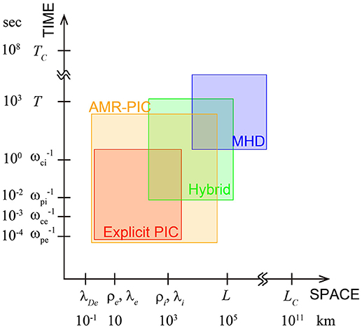
Figure 1. Typical spatial and temporal scales in the Earth's magnetotail together with the ranges that each simulation model can cover. Here, λDe is the electron Debye length, ρs = vth, s/ωcs the gyro radius of species s (i for the ions and e for the electrons) with the thermal velocity, λs = c/ωps the inertia length of s, L the size of the Earth's magnetosphere with T the duration of the substorm growth phase, and LC the collision mean free path with TC the collision time. The scales are estimated, based on Ti = 1keV, Te = 100eV, n = 0.3cm−3, and B = 30nT.
In order to bridge this gap, the present study has employed the adaptive mesh refinement (AMR) to the PIC code. The AMR technique subdivides computational cells locally in space and dynamically in time, achieving dynamically adaptive meshes to increase the dynamic range to be solved. For simulation of the current sheet evolution, the AMR-PIC code is designed to provide fine meshes only around the central current sheet where the plasma density is high, i.e., the electron scales are small, as represented by the electron inertia length λe = c/ωpe (c and ωpe are the speed of light and the electron plasma frequency, respectively). In most of the simulation domain outside the central current sheet, much coarser meshes are used, which enables much more efficient PIC simulation than the usual one, where all the simulation domain must be covered by the finest meshes. It is worth noticing that similar efforts have been made to bridge the gap between the electron and MHD scales, by developing a multi-level multi-domain method [20] and an embedded PIC method in MHD [21].
The AMR-PIC code uses the same equations as the usual explicit PIC code, where the Maxwell equations are solved on the staggering grids and the particle velocities and locations are advanced by the Buneman-Boris method. The main difference between the AMR-PIC and the usual PIC is in the data structure for the quantities defined on the grids. In the usual PIC code, the data is treated on an array with multiple dimensions consistent with spatial dimensions of the simulation domain. Each data location on the array corresponds to the spatial location in the simulation domain. Such the data structure has a great advantage in solving the finite differential equations, since the access to the data on the neighboring grids is very easy. In the AMR-PIC code, on the other hand, the data is aligned on a 1D array independent of the spatial location in the simulation domain. The 1D data structure enables flexible allocation of the data on the spatial grids, regardless of the grid size, so that it facilitates the implementation of the dynamically adaptive meshes. In order to solve the finite differential equations, each data residing closely in space is connected by a set of pointers that are used to identify the neighboring grids.
The fine cells are generated on the coarser cells. The Maxwell equations are solved on each cell level separately. In the region where different cell levels are overlapped, the numerical solutions from fine level cells are employed on coarse level cells. It is also necessary to define the boundary conditions for each cell level. They are provided due to an interpolation of the solutions from the coarser level cells, so that the magnetic fluxes through the cell surfaces are conserved. The particle velocities and locations are advanced using the field data on the finest level cells accessible at each particle's location. The AMR-PIC code performs particle splitting, when the particles move into finer cell region, and also particle coalescence, when they move out from the region. The particle splitting and coalescence are needed to control the number of particles per cell and to suppress the numerical noise raised due to low statistics of the particles.
Figure 2 shows an example of the AMR-PIC simulation in the 2D plane orthogonal to the initial magnetic field. The initial profile employed is the Harris-type current sheet [39] with no guide field, such as Bx(z) = −B0tanh(z/δ) and , where nb and δ are the background density and the half width of the current sheet, respectively, and are set as nb = 0.044n0 and δ = 0.5λi with λi = c/ωpi the ion inertia length based on n0. The ion-to-electron mass ratio is mi/me = 100. The other parameters are Ti/Te = 3.0 and vth, e/c = 0.15 with . Each computational cell can be subdivided into four cells in the 2D case. The criteria for the subdivision are ΔL ≥ 2.0λDe or Vey ≥ 2.0VA at the center of each cell with the size ΔL, where λDe is the local electron Debye length and VA is the Alfvén velocity based on B0 and n0. The criterion for the electron bulk velocity is helpful to pick up the locations where the electron-scale structures are likely formed due to the local super-Alfvénic acceleration. The number of the total refinement levels allowed in the simulation is fixed through the run to be four. The normalization parameters are mi for mass, e for charge, λi for length, and VA for velocity. As seen in Figure 2, the distribution of the refinement meshes is dynamically changed in accordance with the current sheet evolution. We found that the AMR works on the current sheet problems very effectively and, in most cases, saves more than 90% of the computational memory and computational time.
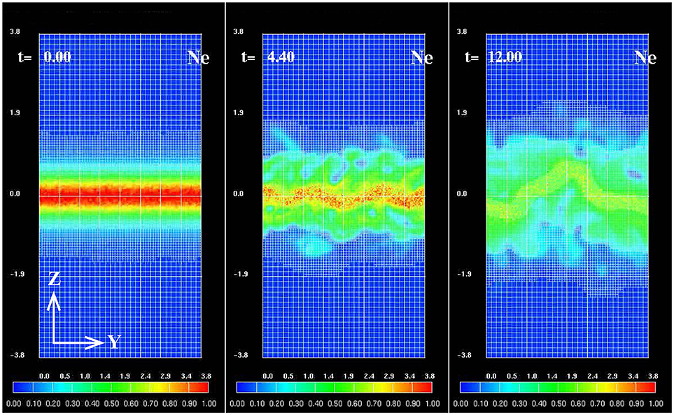
Figure 2. Results from 2D AMR-PIC simulation in the yz plane showing time evolution of the electron density (color contours) with the distribution of the computational meshes (white grids).
The present study focuses on a large-scale evolution of collisionless magnetic reconnection. The simulation is performed in the 2D xz plane that is orthogonal to the initial current density. The initial conditions are the same as those in the above example in the yz plane, except that the current sheet width is δ = λi in this simulation. The boundary conditions employed are “open” both in the inflow (z) and outflow (x) directions, so that both of the particles and magnetic fluxes can smoothly pass across the boundaries. The system size is Lx × Lz = 655λi × 328λi, which is entirely covered by base-level cells (coarsest cells) with ΔLB = 0.08λi and can be locally subdivided up to the dynamic range level with ΔLD = 0.02λi. Thus, the highest resolution in space, evaluated by the effective number of the finest cells, is 32, 768 × 16, 384. The maximum number of particles used is ~1010 for each species, indicating that the simulation is carried out with only ~1TB memory. The analyses in this paper are performed for the base level cells.
Results
The simulation is initiated with a small island to the out-of-plane component of the vector potential. This island provides a small perturbation to the magnetic field around the center of the simulation domain and facilitates the onset of magnetic reconnection. Once the reconnection process has been triggered, the rate of reconnection quickly reaches a quasi-steady value of ER~0.1, where ER is evaluated by the out-of-plane electric field at the x-line and is normalized to the instantaneous values in the inflow region. During the fast reconnection, the electron current layer formed around the x-line is elongated in the outflow direction and is subject to plasmoid formations. Repeating the electron layer elongation [11] and plasmoid ejection [40], the reconnection exhaust expands to a distance far downstream of the x-line on the order of 100λi.
In Figure 3A, the ion flow pattern in the quasi-steady phase as well as the field line structure are shown. The exhaust region dominated by the intense outflow jet, i.e., |Vix|≫|Viz|, is clearly separated from the inflow region characterized by the vertical flow with |Vix|≪|Viz|. Therefore, the isoline of |Vix|−|Viz| = 0, indicated by the thick black curves, can be a good indicator of the interface between the inflow and outflow regions. The local energy exchange between the electric and magnetic field and plasma is carried out through , such that
where ms and are mass and distribution function, respectively, for species s (s = iore). As described in these equations, expresses the local consumption of the electric and magnetic energy, leading to the local enhancement of the ion and electron energy without energy fluxes.
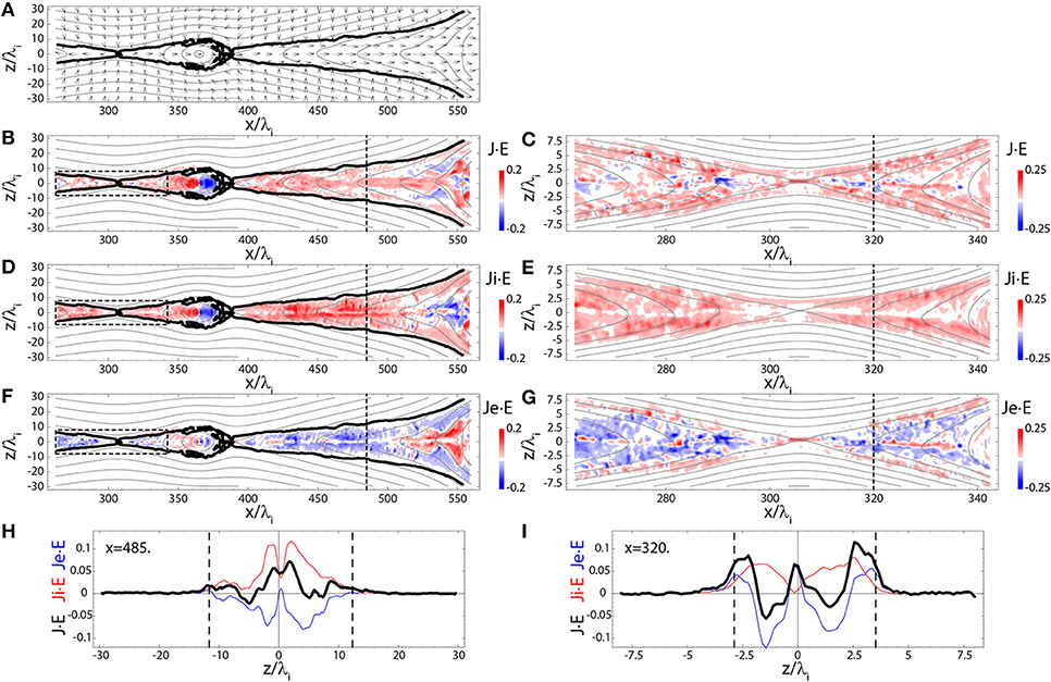
Figure 3. Results from 2D AMR-PIC simulation of magnetic reconnection at tωci = 140 in the xz plane showing (A) ion flow vectors, (B C) , (D E) , (F G) , and (H I) 1D profiles along z of (black curve), (red curve), and (blue curve), at (H) x/λi = 485 and (I) x/λi = 320. The locations of the 1D profiles in (H,I) are indicated by dashed lines in (B,D,F) and (C,E,G), respectively. Thick black curves in (A,B,D,F) represent the isolines of |Vix|−|Viz| = 0. These locations are also indicated by dashed lines in (H,I). Dashed boxes in (B,D,F) show the areas magnified in (C,E,G), respectively. Gray curves in (A–G) are the magnetic field lines.
Figures 3B–G show the energy conversions (i.e., , , and ) in the reconnection region. In the region far downstream of the x-line, where the distance from the x-line is on the order of 100λi, the energy conversion occurs near the center of the exhaust rather than around the exhaust boundaries (Figure 3B). This is also apparent in Figure 3H, where the 1D profiles show the peaks of near z = 0. The energy conversion is mainly caused by the ion energy gain near the exhaust center (Figures 3D,H). This picture is consistent with the ion particle dynamics discussed in Fujimoto and Takamoto [22], where the ion acceleration is carried out through the Speiser-type motion in the current layer formed in the exhaust center. Thus, the mechanism for the ion energization is significantly different from that expected in the MHD reconnection model where plasma acceleration occurs at slow mode shocks separating the inflow and outflow regions.
It is interesting to note that the electrons lose energy in the most part of the exhaust except for the very localized region near the exhaust center (Figures 3F,H). This is because the electron outflow inside the exhaust is mostly guided by the magnetic field, so that the out-of-plane flow direction is in the −y direction due to the Hall magnetic field. This direction turns out to be the same as that of the reconnection electric field, which results in the net energy loss of the electrons. Only in the central region of the exhaust on the scale of λe, the electrons can be unmagnetized, so that they are effectively accelerated due to the reconnection electric field, leading to .
In the region near the x-line, where the distance from the x-line is on the order of 10λi, it is found that the profile is significantly different from that in the region far downstream of the x-line (Figures 3C,I). As shown in Figure 3I, positive energy conversion has three peaks, i.e., at the exhaust center and at the exhaust boundaries. Distinct from the far downstream region, the positive energy conversion is mostly contributed by the electrons near the x-line. In particular, the electron energy gain is remarkable at the exhaust boundaries as well as the exhaust center where the electron magnetization breaks. In fact, in the exhaust boundaries near the x-line, the electrons are strongly accelerated toward the x-line due to double layers (i.e., localized parallel electric fields) [41], which results in near the exhaust boundaries.
The ion energy gain is positive throughout the exhaust near the x-line (Figures 3E,I), consistent with an earlier research [7], except in the central exhaust. In the present simulation, has a dip in the central exhaust, because the meandering ions quickly pass through this region without sufficient time for the acceleration due to the reconnection electric field. However, such the dip did not appear in the earlier research [7]. This is possibly because the earlier research imposed a small guide field throughout the simulation domain, which deformed the meandering orbits and resulted in more effective acceleration in the central exhaust. Similar dip in also appears at the x-line (x/λi ≈ 306) for the same reason as in the exhaust. Instead of , the electron energy gain, , dominates significantly at the x-line. It is known that the energy gain at the x-line is non-reversible and results in the magnetic dissipation to drive reconnection [42]. However, the magnetic dissipation is dominant only in very vicinity of the x-line (typically within ~10λe from the x-line), while most energy conversion occurs in the exhaust as modeled by Petschek [15].
It has been stated in earlier simulations with relatively smaller system [e.g., 43, 44] that a leading edge of the outflow jet, so-called the dipolarization front, is a major region of the ion energy conversion. However, the front region is very localized in space, so that the role of the energy conversion there becomes limited, as the exhaust expands far downstream from the x-line on the order of 100λi. Figure 4 shows the snap shots of the energy conversion in a broad area from the x-line region to the dipolarization front. Although the energy conversion rate is very high in the localized region of the front, the impact on the total energy conversion through the reconnection process is limited because of the locality. Furthermore, it is found that there is a region around the front where the ion energy gain is strongly negative. In this region, the magnetic field is compressed by the dynamic pressure of the outflow jet, that is, work is done by plasma to the magnetic field. In conclusion, the major energy conversion is carried out in the exhaust rather than in the outflow jet front, if the reconnection region has expanded sufficiently.
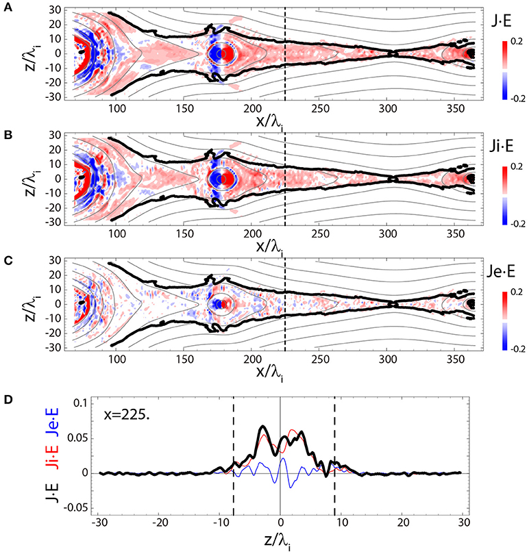
Figure 4. Results from the same simulation run and at the same time as in Figure 3, but focusing on the left-hand side of the x-line. The formats for (A–D) are the same as those for (B,D,F,H), respectively, in Figure 3.
The effect of plasmoid is also small in terms of . As shown in Figures 3, 4, the intensity of is temporarily high inside the plasmoids both in positive and negative senses. The net energy gain is found to be almost zero, so that the plasmoid itself has little contribution to the energy exchange. The current sheet structure is temporarily affected by the plasmoid passing through the exhaust. However, the energy conversion process is not changed between before (Figure 3H) and after (Figure 4D) the plasmoid passing.
Conclusion
The present study has investigated multi-scale processes of collisionless magnetic reconnection by means of large-scale kinetic simulations. In particular, we have focused on the energy conversion process of the magnetic field energy into the plasma kinetic energy through reconnection. The goal of this study is to reveal how the kinetic process around the x-line connects to large-scale process far downstream of the x-line where the MHD approximation is believed to be valid. For this purpose, we have developed a multi-scale PIC simulation code with the AMR, which employs the dynamically adaptive meshes on the full particle simulation and enables efficient simulation of multi-scale kinetic processes. We have confirmed that the AMR-PIC code can dramatically save the computer resources for the simulation of the current sheet evolution, so that it works as a strong tool for simulating collisionless magnetic reconnection.
The large-scale AMR-PIC simulations have suggested that the energy conversion process in collisionless reconnection differs from that in the MHD reconnection model represented by the Petschek's model [15], even in the region far downstream of the x-line. In the MHD reconnection model, most energy conversion occurs at slow mode shocks formed at the exhaust boundaries (Figure 5A). On the other hand, in collisionless reconnection, most part of energy goes to the ions which energy gain mainly occurs in the current layer formed at the exhaust center (Figure 5B). As discussed in the previous study [22], the ion acceleration is carried out through the Speiser motion [2] that requires the kinetic treatment for the ions. These simulation results imply that collisionless magnetic reconnection could be essentially different from the MHD reconnection in terms of the energy conversion process.
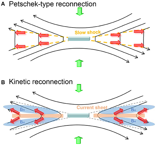
Figure 5. Schematic diagrams showing the ion acceleration process (red arrows) in (A) Petschek-type reconnection and (B) kinetic reconnection. In Petschek-type reconnection, most energy conversion occurs at a pair of slow mode shocks (orange dashed lines) extending from the diffusion region. On the other hand, in kinetic reconnection, the ions are mainly accelerated in the current layer (orange areas) formed at the center of the exhaust and are ejected along the field lines.
It is interesting to note that, near the x-line (on the order of 10λi from the x-line), the electrons are strongly accelerated at the exhaust boundaries, which is not dominant in the exhaust far downstream of the x-line (on the order of 100λi from the x-line). The electron acceleration is mainly due to an electrostatic potential hump (a double layer) that is locally formed in the separatrix regions. The further investigation will be needed to understand why such the double layers are formed only around the x-line and not in the far downstream region.
Data Availability Statement
The simulation data are not available in public because of the large data size and can be obtained by contacting the author (ZnVqaW1vdG9AYnVhYS5lZHUuY24=).
Author Contributions
KF has developed the massively parallelized AMR-PIC code, carried out the large-scale simulations on a supercomputer system, analyzed the simulation data on a local workstation, and derived the scientific interpretation.
Funding
The simulations were performed with support from the computational joint research program of the Institute for Space-Earth Environmental Research (ISEE), Nagoya University, Japan. This research was supported by research grant for the Youth One-Thousand Talent Program of China.
Conflict of Interest Statement
The author declares that the research was conducted in the absence of any commercial or financial relationships that could be construed as a potential conflict of interest.
Acknowledgments
The simulations were performed on the CX400 supercomputer system at Information Technology Center, Nagoya University, Japan.
References
1. Vasyliunas VM. Theoretical models of magnetic field line merging, 1. Rev Geophys. (1975) 13:303–36.
3. Davidson RC, Krall NA. Anomalous transport in high-temperature plasmas with applications to solenoidal fusion systems. Nucl Fusion (1977) 17:1313–72.
4. Lyons LR, Pridmore-Brown DC. Force balance near an X line in a collisionless plasma. J Geophys Res. (1990) 95:20903–9.
5. Cai HJ, Ding DQ, Lee LC. Momentum transport near a magnetic X line in collisionless reconnection. J Geophys Res. (1994) 99:35–42.
6. Fujimoto K, Sydora RD. Particle description of the electron diffusion region in collisionless magnetic reconnection. Phys Plasmas (2009) 16:112309. doi: 10.1063/1.3263694
7. Goldman MV, Newman DL, Lapenta G. What can we learn about magnetotail reconnection from 2D PIC Harris-sheet simulations?. Space Sci Rev. (2015) 199:651–88. doi: 10.1007/s11214-015-0154-y
8. Yamada M, Yoo J, Jara-Almonte J, Ji H, Kulsrud RM, Myers CE. Conversion of magnetic energy in the magnetic reconnection layer of a laboratory plasma. Nat Commun. (2014) 5:4774. doi: 10.1038/ncomms5774
9. Cai HJ, Lee LC. The generalized Ohm's law in collisionless magnetic reconnection, Phys Plasmas (1997) 4:509–20.
10. Hoshino M, Mukai T, Yamamoto T, Kokubun S. Ion dynamics in magnetic reconnection: Comparison between numerical simulation and Geotail observations. J Geophys Res. (1998) 103:4509–30.
11. Fujimoto K. Time evolution of the electron diffusion region and the reconnection rate in fully kinetic and large system. Phys Plasmas (2006) 13:072904. doi: 10.1063/1.2220534
12. Nakamura MS, Fujimoto M, Maezawa K. Ion dynamics and resaltant velocity space distribution functions in the cource of magnetic reconnection. J Geophys Res. (1998) 103:4531–46.
13. Arzner K, Scholer M. Kinetic structure of the post plasmoid plasma sheet during magnetotail reconnection. J Geophys Res.(2001) 106:3827–44. doi: 10.1029/2000JA000179
14. Wygant JR, Cattell CA, Lysak R, Song Y, Dombeck J, McFadden J, et al. Cluster observations of an intense normal component of the electric field at a thin reconnecting current sheet in the tail and its role in the shock-like acceleration of the ion fluid into the separatrix region. J Geophys Res. (2005) 110:A09206. doi: 10.1029/2004JA010708
15. Petschek HE. Magnetic field annihilation. in AAS-NASA Symposium on the Physics of Solar Flares. NASA Spec. Publ. SP-50 (1964) p. 425–39.
16. Feldman WC, Schwartz SJ, Bame SJ, Baker DN, Birn J, Gosling JT, et al. Evidences for slow-mode shocks in the deep geomagnetic tail. Geophys Res Lett. (1984) 11:599–602.
17. Saito Y, Mukai T, Terasawa T, Nishida A, Machida S, Hirahara M, et al. Slow-mode shocks in the magnetotail. J. Geophys. Res. (1995) 100:23567–81.
18. Seon J, Frank LA, Paterson WR, Scudder JD, Coroniti FV, Kokubun S, et al. Observations of a slow-mode shock t the lobe-plasma sheet boundary in Earth's distant magnetotail. Geophys Res Lett. (1995) 22:2981–4.
19. Fujimoto K. A new electromagnetic particle-in-cell model with adaptive mesh refinement for high-performance parallel computation. J Comput Phys. (2011) 230: 8508–26. doi: 10.1016/j.jcp.2011.08.002
20. Innocenti ME, Lapenta G, Markidis S, Beck A, Vapirev A. A multi level multi domain method for particle in cell plasma simulations. J Comput Phys. (2013) 238:115–40. doi: 10.1016/j.jcp.2012.12.028
21. Tóth G, Chen Y, Gombosi TI, Cassak P, Markidis S, Peng IB. Scaling the ion inertial length and its implications for modeling reconnection in global simulations. J Geophys Res. (2017) 122:10336–55. doi: 10.1002/2017JA024189
22. Fujimoto K, Takamoto M. Ion and electron dynamics generating the Hall current in the exhaust far downstream of the reconnection x-line. Phys Plasmas (2016) 23:012903. doi: 10.1063/1.4940322
23. Liu Y-H, Drake JF, Swisdak M. The structure of the magnetic reconnection exhaust boundary, Phys Plasmas (2012) 19:022110. doi: 10.1063/1.3685755
24. Le A, Egedal J, Ng J, Karimabadi H, Scudder J, Roytershteyn V, et al. Current sheets and pressure anisotropy in the reconnection exhaust. Phys Plasmas (2014) 21:012103. doi: 10.1063/1.4861871
25. Ugai M, Tsuda T. Magnetic field-line reconnection by localized enhancement of resistivity. Part 1. Evolution in a compressible MHD fluid. J Plasma Phys. (1977) 17:337–56.
26. Sato T, Hayashi T. Externally driven magnetic reconnection and a powerful magnetic energy converter. Phys Fluids (1979) 22:1189–202.
27. Ugai M. Computer studies on powerful magnetic energy conversion by the spontaneous fast reconnection mechanism. Phys Plasmas (1995) 2:388–97.
29. Birn J, Drake JF, Shay MA, Rogers BN, Denton RE, Hesse M, et al. Geospace environmental modeling (GEM) magnetic reconnection challenge. J Geophys Res. (2001) 106:3715–9. doi: 10.1029/1999JA900449
30. Kuznetsova MM, Hesse M, Rastätter L, Taktakishvili A, Toth G, De Zeeuw DL.et al. Multiscale modeling of magnetospheric reconnection. J Geophys Res. (2007) 112:A10210. doi: 10.1029/2007JA012316
31. Winske D, Yin L, Omidi N, Karimabadi H, Quest K. Hybrid simulation codes: past, present and future - A tutorial. In: Büchner J, Dum CT, Scholer M, editors. Space Plasma Simulation. Lecture Notes in Physics, Vol. 615. Berlin: Springer (2003). p. 136–65.
32. Pritchett PL. Particle-in-cell simulations of magnetosphere electrodynamics, IEEE Trans Plasma Sci. (2000) 28:1976–90.
33. Tanaka M. The macro-EM particle simulation method and a study of collisionless magnetic reconnection. Comput Phys Commun. (1995) 87:117–38.
34. Chen G, Chacón L, Barnes DC. An energy- and charge-conserving, implicit, electrostatic particle-in-cell algorithm. J Comput Phys. (2011) 230:7018–36. doi: 10.1016/j.jcp.2011.05.031
35. Markidis S, Lapenta G. The energy conserving particle-in-cell method. J Comput Phys. (2011) 230:7037–52. doi: 10.1016/j.jcp.2011.05.033
36. Brackbill JU, Forslund DW. An implicit method for electromagnetic plasma simulation in two dimensions. J Comput Phys. (1982) 46:271–308.
37. Langdon AB, Cohen BI, Friedman A. Direct implicit large time-step particle simulation of plasmas. J Comput Phys. (1983) 51:107–38
38. Gonzalez-Herrero D, Boella E, Lapenta G. Performance analysis and implementation details of the energy conserving semi-implicit method code (ECsim). Comput Phys Commun. (2018) 229:162–9. doi: 10.1016/j.cpc.2018.03.020
39. Harris EG. On a plasma sheath separating regions of oppositely directed magnetic field. Nuovo Cimento (1962) 23:115–21.
40. Daughton W, Karimabadi H. Collisionless magnetic reconnection in large-scale electron-positron plasmas. Phys Plasmas (2007) 14:072303. doi: 10.1063/1.2749494
41. Fujimoto K. Wave activities in separatrix regions of magnetic reconnection, Geophys Res Lett. (2014) 41:2721–8. doi: 10.1002/2014GL059893
42. Zenitani S, Hesse M, Klimas A, Kuznetsova M. New measureof the dissipation region in collisionless magnetic reconnection. Phys Rev Lett. (2011) 106:195003. doi: 10.1103/PhysRevLett.106.195003
43. Sitnov MI, Swisdak M, Divin AV. Dipolarization fronts as a signature of transient reconnection in the magnetotail. J Geophys Res. (2009) 114:A04202. doi: 10.1029/2008JA013980
Keywords: magnetic reconnection, energy conversion, cross-scale coupling, particle-in-cell code, adaptive mesh refinement, multi-scale kinetic simulation
Citation: Fujimoto K (2018) Multi-Scale Kinetic Simulation of Magnetic Reconnection With Dynamically Adaptive Meshes. Front. Phys. 6:119. doi: 10.3389/fphy.2018.00119
Received: 10 July 2018; Accepted: 28 September 2018;
Published: 18 October 2018.
Edited by:
Vladimir I. Kolobov, CFD Research Corporation, United StatesReviewed by:
Giovanni Lapenta, KU Leuven, BelgiumMaria Elena Innocenti, Jet Propulsion Laboratory, United States
Copyright © 2018 Fujimoto. This is an open-access article distributed under the terms of the Creative Commons Attribution License (CC BY). The use, distribution or reproduction in other forums is permitted, provided the original author(s) and the copyright owner(s) are credited and that the original publication in this journal is cited, in accordance with accepted academic practice. No use, distribution or reproduction is permitted which does not comply with these terms.
*Correspondence: Keizo Fujimoto, ZnVqaW1vdG9AYnVhYS5lZHUuY24=