- 1Computational Science and Technology Department, Electrical Engineering and Computer Science School, KTH Royal Institute of Technology, Stockholm, Sweden
- 2Centre for Plasma Astrophysics, KU Leuven, Leuven, Belgium
Particle-in-Cell (PIC) methods are widely used computational tools for fluid and kinetic plasma modeling. While both the fluid and kinetic PIC approaches have been successfully used to target either kinetic or fluid simulations, little was done to combine fluid and kinetic particles under the same PIC framework. This work addresses this issue by proposing a new PIC method, PolyPIC, that uses polymorphic computational particles. In this numerical scheme, particles can be either kinetic or fluid, and fluid particles can become kinetic when necessary, e.g., particles undergoing a strong acceleration. We design and implement the PolyPIC method, and test it against the Landau damping of Langmuir and ion acoustic waves, two stream instability and sheath formation. We unify the fluid and kinetic PIC methods under one common framework comprising both fluid and kinetic particles, providing a tool for adaptive fluid-kinetic coupling in plasma simulations.
1. Introduction
Particle-in-Cell (PIC) methods are among the most popular computational methods for plasma simulations. There are two major families of PIC methods: the first one comprises the fluid PIC methods that solve the plasma equations in fluid approximation such as magnetohydrodynamic (MHD); the second one includes kinetic PIC methods for solving the kinetic equations of collisionless plasmas.
Quite surprisingly, the fluid and kinetic PIC methods originated and evolved rather independently. The fluid PIC method was first developed in the Sixties by Harlow to solve the fluid equations by advecting fluid quantities (mass, momentum, and energy) with computational particles [1]. New fluid PIC schemes were developed to decrease numerical diffusion and to solve plasma and material science problems [2, 3]. In particular, the fluid PIC method eventually merged with the Material Point Method for simulating continuous materials [4]. FLIP MHD [5] and Slurm [6] are among the most successful fluid PIC codes for plasma simulations.
The first kinetic PIC methods were developed by Buneman and Dawson in the late Fifties and early Sixties to model collisionless plasma [7, 8]. After their inception, the development of kinetic PIC methods focused more on increasing numerical stability with large simulation time steps [9, 10] and ensuring energy conservation [11–13]. VPIC [14] and iPIC3D [15–17] are among the most widely used kinetic PIC codes for plasma simulations.
Although the two PIC families developed independently with little cross-fertilization, they share the same conceptual framework [18] as they both use computational particles for solving the advection term in the governing equations. The goal of this work is to unify and couple the fluid and kinetic PIC methods under the same framework by allowing the PIC computational particles to be polymorphic and have either fluid or kinetic nature. A major result of this work is the possibility of a fluid particle to become kinetic enabling a seamless fluid-kinetic coupling within the PIC method.
How to couple fluid and kinetic models within the same computational framework is a topic of several recent studies and projects [19–22]. The fluid-kinetic PIC method is an extension of the implicit-moment PIC method [9] using particles to calculate the pressure tensor without relying on an ad-hoc equation of state [23]. The MHD-EPIC (MHD with Embedded PIC) by Daldorff et al. [24] is probably the most successful realization of coupling a PIC code, iPIC3D, and a fluid code, BATS-R-US, under the Space Weather Modeling Framework (SWMF) [25]. In this implementation, the whole computational domain is modeled by solving the MHD equations while the selected regions of space where kinetic effects are important are modeled with the kinetic PIC method. The coupling is achieved by feeding the MHD results to the kinetic solver via boundary conditions while the kinetic results replace the MHD in the specified domain. The MHD-EPIC method has been successfully used to model planetary magnetospheres [26–29].
This work is inspired by the Vlasov spectral methods using Hermite polynomials [30] and combining fluid and kinetic models within the same framework [31]. In fact, by dynamically changing the number of Hermite polynomials during the simulation, it is possible to smoothly transition from fluid to kinetic within the same framework [32]. In the spirit of these Vlasov spectral methods, this work investigates how to smoothly transition from fluid to kinetic within the PIC framework by transforming fluid particles to kinetic particles.
We propose a novel PIC method, PolyPIC, using polymorphic computational particles that allow for a smooth transition from fluid to kinetic approach. The PolyPIC method is tested against four standard benchmark problems, showing that it provides a seamless transition from fluid to kinetic modeling under the same computational framework. The paper is organized as follows. Section 2 presents the PolyPIC governing equations, explains the algorithm, discretization, and implementation. Section 3 presents the results of testing the PolyPIC method against standard benchmark problems. Finally, section 4 summarizes this work, discusses its potential and limitations, and outlines future developments.
2. The Polymorphic-Particle-in-Cell Method
In this section, we present the governing equations, the Polymorphic-Particle-in-Cell (PolyPIC) algorithm, its discretization, and numerical stability conditions.
2.1. Governing Equations
The microscopic state of a plasma species α (electrons or ions) is described by the distribution function fα(x, v, t) that provides the number of plasma particles in the neighborhood of the position x and velocity v in the six-dimensional coordinate-velocity phase space. The evolution of a collisionless plasma species α with mass mα and charge qα in the presence of an electric field E (for sake of simplicity, magnetic field is absent) is governed by the Vlasov equation, which is a conservation law for the phase space density:
where t is time, x and v are the coordinates in the position and velocity spaces. The Vlasov equation provides the full time-dependent description of the plasma and allows modeling of all plasma processes which depend on particle velocity, such as resonance phenomena. However, the numerical solution of the Vlasov equation in multi-dimensional phase space is often prohibitive as it requires to resolve the smallest time and space scales in the system.
The macroscopic state of the plasma species α can be conveniently characterized by the fluid approach, in terms of its mass density (ρα, m) or charge density (ρα, c), fluid bulk velocity (uα), internal energy (Iα), and pressure (pα). If we neglect heat flux, heat sources, viscosity, and external forces, the evolution of such system is determined by the conservation of mass, momentum, and energy, accompanied with an equation of state (EoS):
The above fluid quantities used to describe the plasma are essentially the averages of the distribution function fα(x, v, t) in the velocity space. The fluid equations can be derived from the first three moments of Vlasov equation (see e.g., 33). To compute each moment, the Vlasov equation is multiplied by the corresponding power of v and integrated over the velocity space:
The fluid approximation drastically simplifies the treatment of the evolution of plasma, but loses information about individual particles, therefore it can not describe microscopic phenomena.
In both kinetic and fluid electrostatic models, and in the electric field E can be described in terms of the electrostatic potential Φ
and is governed by the Poisson's equation
where is the net charge density of the plasma.
2.2. Algorithm
The algorithms of fluid PIC methods are discussed in detail in Bacchini et al. [3], Olshevsky et al. [6], and Brackbill et al. [34], while kinetic PIC methods are extensively presented in two textbooks [35, 36]. In essence, both fluid and kinetic PIC methods are semi-Lagrangian numerical methods. The main idea of the PIC method is in using computational particles to calculate the advection term (u·∇) of the governing equation(s), the Vlasov Equation 1, or the fluid (Equations 2). This step for calculating the advection term is called Lagrangian step. The remaining terms of governing equations are solved on a discrete computational grid. This other step is called Eulerian step.
At each PIC computational cycle, the advection is computed by updating computational particle positions and velocities xp, vp for both fluid and kinetic particles. In addition, particle internal energy ep is also updated in the case of fluid particles. Each polymorphic particle carries mass mp and charge qp. These two quantities are calculated initially dividing the total charge and mass per cell by the number of particles per cell. While it is possible to have different mp and qp, particles belonging to the same species have the same mp and qp in this work.
In the fluid PIC, the mass density (ρm), fluid velocity (u), internal energy (I), and pressure (p) are defined on the grid. On the other hand, only the charge density (ρc) is defined in the electrostatic kinetic PIC method. Because PolyPIC combines fluid and kinetic PIC methods, ρm, ρc, u, I, and p are defined on the grid in PolyPIC. In addition, the electrostatic field quantities, electric field (E), and electrostatic potential (Φ), are defined on the grid.
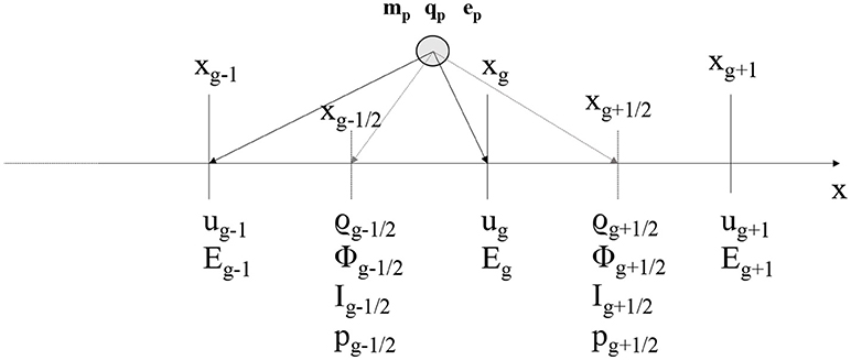
Our algorithm uses a staggered grid where u and E are defined on the grid nodes with subscripts …, g−1, g, g+1, …, while ρc, ρm, Φ, and I are defined on the centers of grid cells with subscripts …, g−1/2, g + 1/2, …, as illustrated in Figure 1. Such discretization makes computation of gradients straightforward (the derivative of a cell-based quantity is a node quantity, and vice versa). In addition, a staggered grid is necessary to keep the magnetic field solenoidal without using artificial divergence cleaning, when the algorithm is extended to magnetized plasmas.
At any time in the PIC algorithm, it is possible to move from particle quantities to grid quantities simply using interpolation functions. Properties on grid points xg are calculated by means of the interpolation functions W(xg−xp) (dropping the α subscript in the notation)
Several interpolation functions can be used. In this work, piece-wise linear interpolation functions [35, 36] are used:
In the fluid PIC method, the pressure on each grid point is derived from I using and Equation of State (EoS). In this work, we use the ideal gas EoS:
where γ = cp/cV is the specific heats ratio.
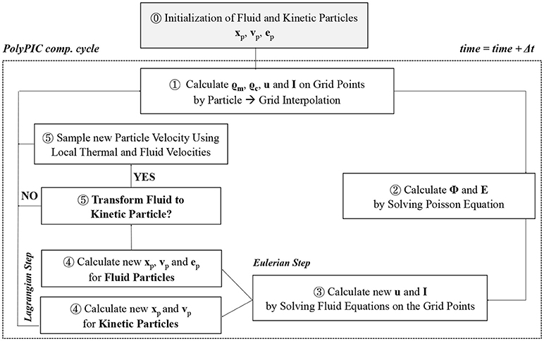
The PolyPIC method comprises an initialization (⓪ in Figure 2) for setting up the simulation parameters and a computational cycle that is repeated at each simulation time step. The computational cycle consists of five stages ➀–➄, as illustrated in Figure 2.
ⓤInitialization. During the initialization phase, fluid quantities (densities and fluid velocity) are defined on the grid and particles are set to be either fluid or kinetic. Particle positions are typically initialized as uniform in space. If particle is fluid, its mass and charge are determined from the local mass and charge densities, while its velocity is set to the local fluid velocity u. If particle is kinetic, its charge and mass are still calculated from local densities, but its velocity is randomly sampled from a Maxwellian distribution centered at u, with the variance equal to the thermal velocity.
After the initialization, the following five phases are carried out at each computational cycle.
➀Interpolation Particles → Grid. The values of the fluid quantities on the grid points (ρm, ρc, u, and I) are computed using the particle to grid interpolation functions (Equation 6 and Figure 1). It is important to note that both kinetic and fluid particles participate in this interpolation step. Because of the thermal spread of kinetic particles, the quantities interpolated from kinetic particles are affected by thermal noise.
➁ Electric Field Calculation on the Grid. After the particle to grid interpolation, it is possible to calculate the net charge density . The electrostatic potential Φ is computed by solving the Poisson's equation (Equation 5) on the grid. In this work, we use one dimensional geometry and finite difference discretization of Equation (5) resulting in an algebraic equation for each grid point g + 1/2:
The set of equations for each grid point constitutes a tridiagonal linear system that can be solved to find Φ. After the solution of the linear solver, the electric field is calculated from Φ by discretizing Equation (4) with finite difference:
➂ Update Grid Quantities (Eulerian Step). In this phase, the new u and I values are calculated solving the fluid equations on the grid without the advection term. The momentum and energy fluid equations to be solved on the grid are:
where μ is the artificial bulk viscosity.
These equations are discretized in time and space in 1D geometry as follows:
where n is the time level of the discretization and .
In this work, we use an artificial bulk viscosity μ that has been proposed by Kuropatenko [37] and Chandrasekhar [38]. This artificial bulk viscosity is non-zero only on grid cells for which ∇·u > 0 and is formulated as follows [39],
where |Δu| = |Δux+Δuy+Δuz| is the velocity jump across the grid cell, is the adiabatic sound speed, c1 and c2 are constants.
➃ Update Particle Quantities (Lagrangian Step). In this phase, the new particle quantities are calculated to perform advection of the fluid and kinetic quantities. We use an explicit time-marching to advance both fluid and kinetic equations in time.
Kinetic and fluid particle are updated in different ways as they advect different quantities in the fluid and kinetic PIC methods:
• Each fluid particle quantity is updated by solving the Ordinary Differential Equations (ODEs):
The discretized equations in 1D, using changes in fluid velocity and internal energy to reduce numerical diffusion [34, 40], are:
We note that particle position is updated using the previous fluid particle velocity, differently from the fluid PIC method. Interpolated quantities at particle positions are calculated using interpolation functions (this time from particle onto grid):
• Each kinetic particle quantity is updated by solving the ODEs:
The discretized equations are:
The electric field at the particle position is calculated from the values of the electric field defined on the grid using the interpolation function as .
➄ Transforming a Fluid Particle to Kinetic Particle? The PolyPIC algorithm allows us to dynamically flip a particle's type from fluid to kinetic, according to a predefined rule. It is possible to define several rules depending on the problem under study. An obvious choice is to switch from fluid to kinetic particles when fluid particles reach a threshold velocity or acceleration (in practice, we found that a multiple of local thermal velocity is a convenient threshold velocity):
Similarly to other approaches in fluid-kinetic coupling, another obvious choice is to switch to kinetic particles in the regions where the kinetic effects are relevant. For instance, when studying plasma sheath formation close to a wall, it is useful to have kinetic electrons and/or ions close to the wall to model the sheath kinetically. This case is shown in the left panels of Figure 3 where fluid ions become kinetic when entering the spatial regions x < 6 and x > 19. However, we found that this choice creates numerical artifacts between the fluid and kinetic regions. Indeed, our experiments show that if we confine kinetic particles in a given spatial region, an artificial sheath forms at the interface between the kinetic and fluid regions. The formation of this artificial sheath is clear when analyzing the potential Φ profile in proximity of x = 10 and x = 17 (bottom left panel of Figure 3). For this reason, in this work we do not switch to kinetic particles in selected parts of the domain. Instead, we choose a rule based either on reaching a threshold velocity or acceleration so that the transition is smoother and no evident sheath forms between fluid and kinetic regions (bottom right panel of Figure 3).
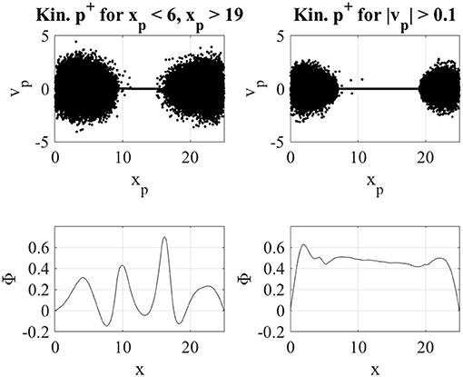
Figure 3. Ion phase space and electrostatic potential Φ for a simulation with ions becoming kinetic when entering the regions x < 6 and x > 15 (left panels). An artificial sheath between the kinetic and the fluid ions is formed. In the right panels, ion phase space and electrostatic potential Φ is shown for a simulation with ions becoming kinetic when their velocity is greater than a threshold velocity (0.1). In this case, the artificial sheath is not formed.
When a fluid particle becomes kinetic, it obtains a new velocity. This velocity is sampled randomly from a Maxwellian distribution centered on the local fluid velocity u|xp, with variance (σ2) equal to the local thermal velocity:
The local (to the particle) fluid and thermal velocity (vth) are calculated using interpolation functions as
In the transformation from fluid to kinetic particle, we assume a Maxwellian distribution function for kinetic particles while different kinds of distribution function might occur in non-equilibrium plasmas.
2.2.1. Numerical Stability
Both fluid and kinetic PIC methods in this work use an explicit discretization in time, and are subject to their respective numerical stability constraints:
• Because we use an explicit formulation of equations in ➂, the fluid PIC simulation time step and grid spacing must satisfy the Courant condition . An implicit discretization of equations with pressure term evaluated half time (stage ➂) would remove this stability condition [40, 34]. In addition, explicit fluid PIC methods are unstable against the ringing instability when the plasma flow is lower than a critical velocity [41].
• The kinetic PIC component requires a time step resolving the plasma period ωpΔt ≤ 0.1 to retain numerical stability. In addition, grid spacing should be smaller than the local Debye length (ΛD) to avoid numerical heating and the finite grid instability (see e.g., [35]).
2.2.2. Implementation
We implement the PolyPIC method in a proof-of-concept Matlab code, available at http://www.github.com/smarkidis/. In our implementation, we use only vector operations with masks to avoid conditional branching and achieve increased performance. The Poisson equation requires the solution of a linear system that is calculated with the Matlab solver for tridiagonal matrices. The interpolation operations that are implemented as a large sparse matrix vector multiplications take most of the simulation time. In most of the simulations presented in section 3, interpolation operations account for more than 50% of the total simulation time.
The interpolation step in phase ➀ of the PolyPIC method requires interpolation of both fluid and kinetic particles onto the grid. Because of the thermal spread of kinetic particles, the fluid quantities calculated with kinetic particles are affected by numerical noise. This noise appears as relatively small discontinuities in the fluid quantities, densities, fluid velocity and pressure. During the update of the fluid quantities in step ➂, spurious oscillations might originate because of these small-scale discontinuities.
To address this problem, we use artificial bulk viscosity in Equation (12) to dissipate these spurious oscillations. In addition, a Laplacian smoothing of fluid quantities is beneficial to eliminate small-scale discontinuities in fluid quantities [35, 42] before solving the fluid equations on the grid (phase ➂). The Laplacian smoothing operation in one dimension on a grid quantity Q is defined as follows:
More than one smoothing pass can be also performed as S(…S(Q)…).
3. Results
We present four different verification tests of the PolyPIC model. The first two tests are the Landau damping of the Langmuir and ion acoustic waves tests, showing the use of fluid ions and kinetic electrons (Langmuir wave test) and kinetic ions and fluid electrons (ion acoustic wave test). The third and fourth tests, the two-stream instability and sheath formation tests, show the dynamic change from fluid to kinetic description within one simulation. All the tests are performed in one-dimensional geometry in the electrostatic limit.
3.1. Landau Damping of Langmuir Waves
The first test is the simulation of a Langmuir wave propagation in a plasma. A Langmuir wave undergoes Landau damping due to kinetic resonance between the wave and electrons moving approximately at the phase velocity of the Langmuir wave. The kinetic energy of such electron population increases at expense of the Langmuir wave damping. For this reason, a kinetic treatment of electrons is required for modeling the Landau damping of Langmuir waves.
We perform a simulation of the Langmuir wave propagation using one population of kinetic electron particles and one population of fluid ion particles. The initial electron thermal velocity is Vthe = 1 with equal temperature for electrons and ions. The charge to mass ratio is set to -1 for electrons and to 1/1,836 for ions. There are 10,000 kinetic electrons and fluid ions per cell. The simulation box of size L = 4πΛD is divided in 64 cells and has periodic boundaries. To initiate the Langmuir wave we perturb the initial positions of kinetic electrons: xp = xp+ 0.1sin(2πxp/L). The simulation step is Δt = 0.1/ωp; a simulation lasts for 150 computational cycles. The specific heat ratio for the fluid ions is γ = 7/5. We perform a two-pass binomial smoothing of the ion fluid quantities at each time step, and no artificial viscosity is introduced (c1 = 0 and c2 = 0 in Equation 13).
The k = 1/ΛD spectral component of the electric field in Figure 4 (asterisks) is compared with the damping rate obtained from the linear theory γ = -0.15139ωp (dashed line) and simulation results of a fluid PIC. To assess the importance of kinetic electrons, we also perform a simulation of Langmuir wave propagation with a fluid PIC simulation. The open circles in Figure 4 represent the electric field spectral component for the fluid PIC simulation, showing that the Langmuir wave is not damped when fluid approach is used.
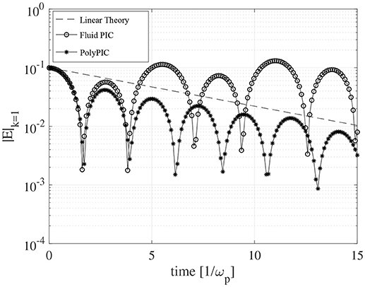
Figure 4. Comparison between linear theory and PolyPIC simulation of Langmuir wave damping. The k = 1/ΛD spectral component of the electric field for the simulation with kinetic electrons and fluid ions (asterisks) decreases as predicted by the linear theory (dashed line). The fluid PIC simulation with both fluid electron and ions (open circles) do not show damping of the Langmuir wave.
3.2. Landau Damping of Ion Acoustic Waves
The second test for the PolyPIC method is similar in nature to the first test of Langmuir wave propagation as it investigates the kinetic damping of an ion acoustic wave. Differently from the previous test, we use fluid electrons and kinetic ions in PolyPIC. As in the previous test, the ion acoustic wave is expected to damp in time because of kinetic effects. The simulation is initialized with 10,000 fluid electrons and kinetic ions per cell. The charge/mass ratio is -1 for electrons and 1/1,836 for ions. The periodic simulation box of size L = 4π is divided in 64 cells. The ion acoustic wave is excited by perturbing the initial positions of the kinetic ions: xp = xp+ 0.2sin(2πxp/L). The initial thermal velocity of ions is and electron/ion temperature ratio is Te/Ti = 5. A simulation lasts for 600 computational cycles with Δt = 0.025/ωp. The specific heats ratio for fluid ions is γ = 5/3. We perform a two-pass Laplacian smoothing (Equation 22) of the ion fluid quantities at each time step before phase ➂, and artificial viscosity with c1 = 10 and c2 = 10 is used in Equation (12).
The ion acoustic wave is damped by the resonant interaction of the wave with particles as shown in Figure 5, where asterisks depict the electric field's first spectral component in the simulation with PolyPIC. A theoretical damping rate - 0.25ωp is plotted with dashed line for comparison. In addition, the results of kinetic PIC with 10,000 electrons and ions per cell (open circles) and fluid PIC (open squares) simulations are shown in Figure 5. The fully kinetic simulation shows a damping rate similar to the rate in the PolyPIC simulation. However, the wave trapping period differs and at the end of the simulation the effects of numerical noise become evident. Additional kinetic PIC simulations with larger number of particles shows a decrease of numerical noise and a convergence to correct representation of wave-particle interaction. On the other hand, fluid PIC simulation misrepresents the physics, and the ion acoustic wave is not damped.
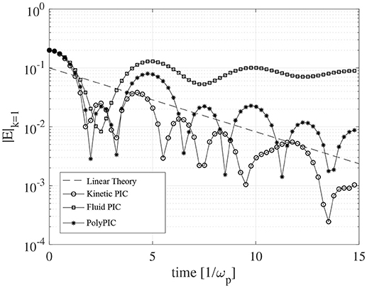
Figure 5. Simulation of ion acoustic propagation in plasma using fully kinetic simulation (open circles), fluid electrons and kinetic ions (asterisks) and fully fluid (open squares) simulations.
3.3. Two-Stream Instability
The two-stream instability test aims at verifying the dynamic change from fluid to kinetic electrons. The two-stream instability is a kinetic instability occurring in presence of two counter-streaming electron beams. The linear growth of the instability can be described correctly by two electron fluid theory [35]. For this reason, the PolyPIC simulation can start from fluid electrons where each beam constitutes a fluid. However, the non-linear part of the instability cannot be described correctly by the two fluid theory and a kinetic treatment is required. During the non-linear part of the instability, many of the fluid electrons undergo strong acceleration and flip their type from fluid to kinetic.
The simulation initializes the two electron beams as two separate fluid particle species with 100 particles/beam/cell in a periodic domain with L = 2π/3.06 divided into 64 grid cells. We initialize the electron beams of relatively cold electrons with thermal speed Vthe = 0.01, and beam drift velocity ± 0.2. Motionless ions provide only a background charge density to neutralize the system (they are not explicitly considered in the simulation). The simulation lasts for 2,100 cycles with Δt = 0.02/ωp. The time step is chosen to resolve electron dynamics during instability and satisfies the numerical stability constraints. The two-stream instability is initiated by perturbing the initial electron positions: xp = xp+ 0.1sin(2πxp/L). The specific heats ratio for electrons in this simulation is γ = 7/5. An artificial viscosity (Equation 13) is used with c1 = 1 and c2 = 1.
In the PolyPIC simulation, fluid electrons become kinetic when they undergo a strong acceleration. Namely, when a particle's fluid velocity variation in a time step is larger than Vthe/10. We found that in practice such a threshold value allows fluid particles to become kinetic during the initial stage of the non-linear part of the instability.
Initially in the PolyPIC simulation, the two electron beams consist of only fluid particles. This is clear from inspecting the top left panel of Figure 6 showing the electron phase space at time 0. Approximately at t = 27/ωp, fluid electrons undergoing a strong acceleration start turning to kinetic. This is visible by the spread of electrons due to thermal noise in the four regions in the top right panel of Figure 6. The extent of these kinetic regions increases with time until a certain moment when it covers the entire simulation domain. Finally, all electrons are kinetic at time t = 42/ωp (bottom right panel of Figure 6).
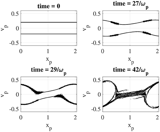
Figure 6. Electron phase space during the two-stream instability at different times. Initially all the electrons are fluid. Electrons undergoing strong acceleration become kinetic. This clear from inspecting the electron phase-space at time = 27, 29/ωp. At time = 42/ωp all the electrons are kinetic. A video of electron phase space is available here.
The PolyPIC method is verified against linear theory prediction of the instability growth rate. The top panel of Figure 7 shows a comparison of the simulated electric field component k = 1 (asterisks) with the instability growth rate of 0.35355ωp, predicted by the linear theory (dashed line). Open circles show the growth of the instability in the two fluid PIC simulation. The two fluid PIC simulation models correctly the linear stage of the instability growth, but then becomes unstable at t = 31/ωp. We note that higher values of artificial viscosity allows the simulation to progress for longer period in the non-linear regime of the instability, but eventually the fluid simulation becomes numerically unstable. The bottom panel of Figure 7 shows the ratio of kinetic electrons over the total number of electrons in the PolyPIC simulation. Initially, all the electrons are fluid. The first electrons become kinetic approximately at t = 26/ωp. The electrons are all kinetic at t = 31/ωp.
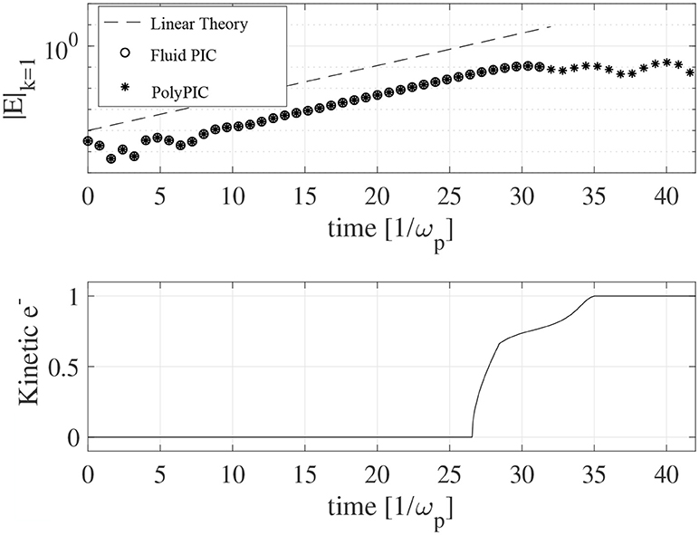
Figure 7. The k = 1 spectral component of the electric field is shown for two fluid PIC simulation (open circles), PolyPIC simulation (asterisks) and linear theory (dashed line) in the top panel. The two fluid PIC simulation becomes unstable during the non-linear stage of the instability. The bottom panel shows the ratio of kinetic electrons over the total number of electrons during the PolyPIC simulation. Initially, all the electrons are fluids; during the non-linear phase of the instability, the electrons become kinetic.
3.4. Plasma Sheaths
The last problem used to test the PolyPIC method is the sheath formation in the proximity of walls. Because of the higher mobility of electrons, initially more electrons exit than ions, leading plasma to have positive potential with respect to the wall.
This simulation is initiated with kinetic electrons and fluid ions. During the simulation, ions can become kinetic if their velocity is greater than a specific threshold velocity. Ions are accelerated close to the domain walls, hence we expect the kinetic regions to form adjacent to the walls. The simulation box with L = 25ΛD long is divided into 256 cells. We eliminate particles exiting the simulation box and fix the electrostatic potential on the walls to 0. Initially, there are 500 electrons and ions per cell. The charge/mass ratio is - 1 for electrons and 1/1,836 for ions. The initial thermal velocity of electrons is Vthe = 1 and electron/ion temperature ratio is 1. The fluid ions become kinetic when they reach a threshold velocity of 40Vthe. The simulation lasts for 2,000 computational cycles with Δt = 0.05/ωp. The specific heats ratio for the fluid ions is γ = 7/5. We perform a two-pass binomial smoothing of the ion fluid quantities, and an artificial viscosity (Equation 13) is used with c1 = 1 and c2 = 1.
Initially all ions in the simulation are fluid and depicted with gray dots in the phase space plot shown in the upper left panel of Figure 8. As the simulation progresses, in proximity of the walls ions reach velocity higher than the threshold velocity and become kinetic. Subsequent panels in Figure 8 show the widening regions adjacent to the walls where kinetic ions are spread by thermal noise. The top panel of Figure 8 shows electrostatic potential at different simulation times. The electrostatic potential remains similar during the simulation and it is not impacted by ions switching from fluid to kinetic. The bottom panel of Figure 9 shows the ratio of kinetic ions over the total number of ions in the PolyPIC simulation. Initially all the ions are fluid. At t = 18/ωp the first ions start turning to kinetic; after this, the number of kinetic ions increases linearly with time.
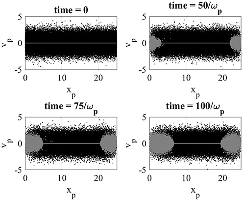
Figure 8. Electron (black dots) and ion (gray dots) phase space in the sheath simulation. Initially all the electrons are kinetic and ions are fluid. If ion particle velocity becomes higher than 40 times the initial ion thermal velocity, the ion particle becomes kinetic. Fluid ion particles become kinetic in the sheath close to the walls (x = 0 and x = L). A video of phase space is available here.
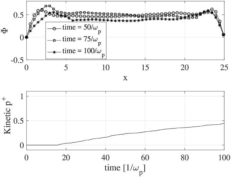
Figure 9. (Top) The electrostatic potential in the simulation domain at three time steps: tωp = 50 (open circles), t = 75/ωp (open squares), t = 100/ωp (asterisks). (Bottom) The ratio of kinetic ions during the sheath simulation.
4. Discussion and Conclusion
A new PIC method using polymorphic computational particles has been formulated and implemented to combine the fluid and kinetic PIC methods under a unified common framework. The PolyPIC method is adaptive as it allows fluid particles to become kinetic when undergoing a strong acceleration or reaching a threshold velocity. We implemented a proof-of-concept code based on the explicit discretization of the governing equations and used it to solve successfully four different test problems.
A first challenge when coupling fluid and kinetic approaches is to eliminate spurious effects occurring at the boundary between fluid and kinetic regions. For instance, we showed that a sheath forms at the interface between the regions with kinetic particles and with fluid particles in the same way a sheath forms when two different plasmas are put in contact. It is preferable to change the type of the particle from fluid to kinetic depending on its velocity instead of its position to allow a smooth transition between the fluid and kinetic regions. Currently, the criterion to switch particles from fluid to kinetic are set empirically. A dedicated study is needed on how to set these criteria automatically.
A second major challenge in coupling fluid and kinetic approaches in the same PIC method is that moments (densities, fluid velocity, …) computed from kinetic particles are not smooth, as fluid quantities typically are, because of the kinetic particle noise. This noise produces small discontinuities in the computed moments which might result in unphysical oscillations. An artificial bulk viscosity introduced into fluid equations effectively remedies the effects of numerical noise. In addition, smoothing and filtering can reduce noise from kinetic particles before updating the fluid quantities. How to eliminate such spurious effects without affecting energy conservation, is a topic of future research.
One of the advantages of fluid PIC method with respect to the kinetic PIC approach is the fact fluid PIC method requires only a small number of particles to describe accurately the evolution of the system. However, kinetic PIC methods typically require a very large number of particles to describe accurately kinetic effects such as wave-particle interaction. In order to use few fluid particles but many kinetic particles when needed, the PolyPIC method requires a particle splitting technique when switching from one fluid particle to many kinetic particles [43].
In this work we did not address the change of a kinetic particle to fluid particle. Presently there is no clear and simple use case to present. However, such techniques can be easily designed. An efficient implementation might require the coalescence of several kinetic particles in one fluid particle.
To conclude, we have unified the fluid and kinetic PIC methods under a unified common framework comprising both fluid and kinetic particles. This approach allows the simulation to change smoothly from fluid to kinetic description in time and space providing a powerful tool for adaptive fluid-kinetic plasma simulations.
Data Availability Statement
The Matlab codes developed for this study can be found in the GitHub repository (http://www.github.com/smarkidis/).
Author Contributions
SM led the development of the method, the implementation and the article preparation. VO contributed to the development and implementation of the method and to the article preparation. CS, SC, GL, and EL contributed to the discussion of the method, results, and to the preparation of the article.
Funding
Funding for the work is received from the Swedish VR grant no. 2017–04508.
Conflict of Interest Statement
The authors declare that the research was conducted in the absence of any commercial or financial relationships that could be construed as a potential conflict of interest.
References
1. Harlow FH. The Particle-in-Cell Method for Numerical Solution of Problems in Fluid Dynamics. Los Alamos Scientific Lab. (1962).
2. Brackbill JU. FLIP MHD - A particle-in-cell method for magnetohydrodynamics. J Comput Phys. (1991) 96:163–92.
3. Bacchini F, Olshevsky V, Poedts S, Lapenta G. A new Particle-in-Cell method for modeling magnetized fluids. Comput Phys Commun. (2017) 210:79–91. doi: 10.1016/j.cpc.2016.10.001
4. Sulsky D, Zhou SJ, Schreyer HL. Application of a particle-in-cell method to solid mechanics. Comput Phys Commun. (1995) 87:236–52.
5. Brackbill J. FLIP MHD: a particle-in-cell method for magnetohydrodynamics. J Comput Phys. (1991) 96:163–92.
6. Olshevsky V, Bacchini F, Poedts S, Lapenta G. Slurm: fluid particle-in-cell code for plasma modeling. J Comput Phys. (Press). doi: 10.1016/j.cpc.2018.06.014
9. Brackbill J, Forslund D. An implicit method for electromagnetic plasma simulation in two dimensions. J Comput Phys. (1982) 46:271–308.
10. Drouin M, Gremillet L, Adam JC, Héron A. Particle-in-cell modeling of relativistic laser–plasma interaction with the adjustable-damping, direct implicit method. J Comput Phys. (2010) 229:4781–4812. doi: 10.1016/j.jcp.2010.03.015
11. Markidis S, Lapenta G. The energy conserving particle-in-cell method. J Comput Phys. (2011) 230:7037–52. doi: 10.1016/j.jcp.2011.05.033
12. Chen G, Chacón L, Barnes DC. An energy-and charge-conserving, implicit, electrostatic particle-in-cell algorithm. J Comput Phys. (2011) 230:7018–36. doi: 10.1016/j.jcp.2011.05.031
13. Lapenta G, Markidis S. Particle acceleration and energy conservation in particle in cell simulations. Phys Plasmas (2011) 18:072101. doi: 10.1063/1.3602216
14. Bowers KJ, Albright BJ, Bergen B, Yin L, Barker KJ, Kerbyson DJ. 0.374 Pflop/s trillion-particle kinetic modeling of laser plasma interaction on Roadrunner. In: Proceedings of the 2008 ACM/IEEE Conference on Supercomputing. Austin, TX: IEEE Press (2008). p. 63.
15. Markidis S, Lapenta G, Uddin R. Multi-scale simulations of plasma with iPIC3D. Math Comput Simul. (2010) 80:1509–19. doi: 10.1016/j.matcom.2009.08.038
16. Peng IB, Markidis S, Vaivads A, Vencels J, Amaya J, Divin A, et al. The formation of a magnetosphere with implicit particle-in-cell simulations. In: 15th Annual International Conference on Computational Science Reykjavík. (2015) p. 1178–87.
17. Peng IB, Vencels J, Lapenta G, Divin A, Vaivads A, Laure E, et al. Energetic particles in magnetotail reconnection. J Plasma Phys. (2015) 81:325810202. doi: 10.1017/S0022377814001123
18. Brackbill J. Particle methods. Int J Numer Methods Fluids (2005) 47:693–705. doi: 10.1002/fld.912
19. Henri P, Cerri SS, Califano F, Pegoraro F, Rossi C, Faganello M, et al. Nonlinear evolution of the magnetized Kelvin-Helmholtz instability: from fluid to kinetic modeling. Phys Plasmas (2013) 20:102118. doi: 10.1063/1.4826214
20. Lapenta G, Pierrard V, Keppens R, Markidis S, Poedts S, Šebek O, et al. SWIFF: Space weather integrated forecasting framework. J Space Weath Space Clim. (2013) 3:A05. doi: 10.1051/swsc/2013027
21. Jordanova VK, Delzanno GL, Henderson MG, Godinez HC, Jeffery C, Lawrence EC, et al. Specification of the near-Earth space environment with SHIELDS. J Atmos Solar-Terrest Phys. (2017) 177:148–59. doi: 10.1016/j.jastp.2017.11.006
22. Innocenti ME, Johnson A, Markidis S, Amaya J, Deca J, Olshevsky V, et al. Progress towards physics-based space weather forecasting with exascale computing. Adv Eng Softw. (2017) 111:3–17. doi: 10.1016/j.advengsoft.2016.06.011
23. Markidis S, Henri P, Lapenta G, Rönnmark K, Hamrin M, Meliani Z, et al. The fluid-kinetic particle-in-cell method for plasma simulations. J Comput Phys. (2014) 271:415–29. doi: 10.1016/j.jcp.2014.02.002
24. Daldorff LK, Tóth G, Gombosi TI, Lapenta G, Amaya J, Markidis S, et al. Two-way coupling of a global Hall magnetohydrodynamics model with a local implicit particle-in-cell model. J Comput Phys. (2014) 268:236–54. doi: 10.1016/j.jcp.2014.03.009
25. Tóth G, Sokolov IV, Gombosi TI, Chesney DR, Clauer CR, De Zeeuw DL, et al. Space weather modeling framework: a new tool for the space science community. J Geophys Res. (2005) 110. doi: 10.1029/2005JA011126
26. Tóth G, Jia X, Markidis S, Peng IB, Chen Y, Daldorff LKS, et al. Extended magnetohydrodynamics with embedded particle-in-cell simulation of Ganymede's magnetosphere. J Geophys Res. (2016) 121:1273–93. doi: 10.1002/2015JA021997
27. Chen Y, Tóth G, Cassak P, Jia X, Gombosi TI, Slavin JA, et al. Global three-dimensional simulation of Earth's dayside reconnection using a two-way coupled magnetohydrodynamics with embedded particle-in-cell model: initial results. J Geophys Res. (2017) 122:10318–35. doi: 10.1002/2017JA024186
28. Tóth G, Chen Y, Gombosi TI, Cassak P, Markidis S, Peng IB. Scaling the ion inertial length and its implications for modeling reconnection in global simulations. J Geophys Res. (2017) 122:10336–55. doi: 10.1002/2017JA024189
29. Ma Y, Russell CT, Toth G, Chen Y, Nagy AF, Harada Y, et al. Reconnection in the martian magnetotail: Hall-MHD with embedded particle-in-cell simulations. J Geophys Res. (2018) 123:3742–63. doi: 10.1029/2017JA024729
30. Delzanno GL. Multi-dimensional, fully-implicit, spectral method for the Vlasov–Maxwell equations with exact conservation laws in discrete form. J Comput Phys. (2015) 301:338–56. doi: 10.1016/j.jcp.2015.07.028
31. Vencels J, Delzanno GL, Manzini G, Markidis S, Peng IB, Roytershteyn V. SpectralPlasmaSolver: a spectral code for multiscale simulations of collisionless, magnetized plasmas. In: Journal of Physics: Conference Series. Vol. 719. Avignon: IOP Publishing (2016). p. 012022.
32. Vencels J, Delzanno GL, Johnson A, Peng IB, Laure E, Markidis S. Spectral solver for multi-scale plasma physics simulations with dynamically adaptive number of moments. Proc Comput Sci. (2015) 51:1148–57. doi: 10.1016/j.procs.2015.05.284
33. Freidberg JP. Ideal Magnetohydrodynamics (Modern Perspectives in Energy). Cambridge, UK: Cambridge University Press (1987).
34. Brackbill JU, Kothe DB, Ruppel HM. FLIP: a low-dissipation, particle-in-cell method for fluid flow. Comput Phys Commun. (1988) 48:25–38.
35. Birdsall CK, Langdon AB. Plasma Physics via Computer Simulation. Boca Raton, FL: CRC Press (2004).
37. Kuropatenko VF. Difference methods for hydrodynamics equations. In: Yanenko NN, Petrovskii IG, editors. Difference Methods for Solutions of Problems of Mathematical Physics, Part 1. Moscow: Trudy Mat. Inst. Steklov (1966). p. 107–37.
39. Caramana EJ, Shashkov MJ, Whalen PP. Formulations of artificial viscosity for multi-dimensional shock wave computations. J Comput Phys. (1998) 144:70–97.
40. Brackbill J, Ruppel H. FLIP: A method for adaptively zoned, particle-in-cell calculations of fluid flows in two dimensions. J Comput Phys. (1986) 65:314–43.
41. Brackbill J. The ringing instability in particle-in-cell calculations of low-speed flow. J Comput Phys. (1988) 75:469–92.
42. Stanier A, Chacón L, Chen G. A fully implicit, conservative, non-linear, electromagnetic hybrid particle-ion/fluid-electron algorithm. arXiv [preprint] arXiv:180307158 (2018).
Keywords: polymorphic-particle-in-cell, fluid-particle-in-cell, plasma simulations, fluid-kinetic simulations, computational plasma physics
Citation: Markidis S, Olshevsky V, Sishtla CP, Chien SWD, Laure E and Lapenta G (2018) PolyPIC: The Polymorphic-Particle-in-Cell Method for Fluid-Kinetic Coupling. Front. Phys. 6:100. doi: 10.3389/fphy.2018.00100
Received: 01 May 2018; Accepted: 23 August 2018;
Published: 04 October 2018.
Edited by:
Fabrice Deluzet, UMR5219 Institut de Mathématiques de Toulouse (IMT), FranceReviewed by:
Anais Crestetto, University of Nantes, FranceGiacomo Dimarco, University of Ferrara, Italy
Copyright © 2018 Markidis, Olshevsky, Sishtla, Chien, Laure and Lapenta. This is an open-access article distributed under the terms of the Creative Commons Attribution License (CC BY). The use, distribution or reproduction in other forums is permitted, provided the original author(s) and the copyright owner(s) are credited and that the original publication in this journal is cited, in accordance with accepted academic practice. No use, distribution or reproduction is permitted which does not comply with these terms.
*Correspondence: Stefano Markidis, bWFya2lkaXNAa3RoLnNl
 Stefano Markidis
 Vyacheslav Olshevsky
 Chaitanya Prasad Sishtla
 Steven W. D. Chien
 Erwin Laure1