 Yu Zhao
 Yuan Huang1
- 1School of Information Engineering, Yangzhou University, Yangzhou, China
- 2College of Hydraulic Science and Engineering, Yangzhou University, Yangzhou, China
The large amount of computing data from hologram calculations incurs a heavy computational load for realistic full-color holographic displays. In this research, we propose a segmented point-cloud gridding (S-PCG) method to enhance the computing ability of a full-color holographic system. A depth camera is used to collect the color and depth information from actual scenes, which are then reconstructed into the point-cloud model. Object points are categorized into depth grids with identical depth values in the red, green, and blue (RGB) channels. In each channel, the depth grids are segmented into M×N parts, and only the effective area of the depth grids will be calculated. Computer-generated holograms (CGHs) are generated from efficient depth grids by using a fast Fourier transform (FFT). Compared to the wavefront recording plane (WRP) and traditional PCG methods, the computational complexity is dramatically reduced. The feasibility of the S-PCG approach is established through numerical simulations and optical reconstructions.
1 Introduction
Recently, computer-generated holography display technology has become a hot topic of three-dimensional (3-D) displays (Park, 2017; Wang et al., 2017; Chen et al., 2020). To realize real-time holographic video display and holographic video communication, researchers have actively studied holographic display and computer-generated hologram technology. However, as the hologram resolution, object size, and refresh rate increase, the data size inevitably increases to achieve the 3-D holographic display technology (Yeom et al., 2014; Sahin et al., 2020; Takenaka et al., 2021). And it is difficult to collect data in real-time and calculate holograms quickly, it is difficult to meet the actual needs. Therefore, the research on fast holographic algorithms for real objects and improving the adaptability of the algorithm has become an urgent problem in a computer-generated holographic 3-D display (Chang et al., 2018; Wu et al., 2019). It is also an unavoidable and necessary problem of computer-generated holographic displays.
To overcome the problem of the slow generation of computer-generated holograms, researchers have carried out a large number of research projects to simplify the generation process of computer-generated holograms. Some researchers use graphics processing units (GPU) to improve computational speed (Pan et al., 2013; Kwon et al., 2016). In these researches, researchers use GPU to calculate the light field on the hologram in parallel processes. Although the calculation time has been greatly shortened, the calculation process is complex and still can not meet the actual needs. Some other researchers also reduce the calculation time by using lookup tables (Zhao et al., 2018a; Cao and Kim, 2019). However, it also requires a lot of memory and additional lookup table generation time. Wavefront recording plane (WRP) (Shimobaba et al., 2009) is a famous acceleration method to overcome the shortcomings of traditional point cloud computing methods. Instead of the complex value on the whole holographic plane, only the complex value of a small area of the WRP is calculated, the calculation time required to generate the computer-generated hologram can be reduced. We have also optimized this algorithm and proposed an algorithm based on this wavefront recording plane surface (WRS) (Zhao et al., 2015), depth ranging wavefront plane (Piao et al., 2020), and uniform ranging multi wavefront recording surface (Sifatul Islam et al., 2020), which accelerate the generation speed of CGH based on the point cloud. However, to determine the light field of the wavefront plane, it is necessary to pre-calculate the light field of the point cloud. The total calculation time of the hologram is still large, and there is still a big gap from the real-time display. Some other scholars have proposed the method with angular spectrum layer (Zhao et al., 2015; Zhao et al., 2016) to generate computer-generated holograms from 3-D scenes. Without paraxial approximation, a fast Fourier transform is used to generate the angular spectrum from the depth layers. These acceleration methods are oriented to the calculation of computer-synthesized virtual 3-D object holograms, rather than real objects.
With the improvement of computer technology and sensor technology, we can conveniently collect the 3-D information of real objects. Because high-quality 3D reconstruction requires a high-resolution depth camera obtaining a high-precision 3D color point cloud model, and the resolution of the hologram needs to meet the pixel size of the spatial light modulator (SLM). Therefore, the amount of calculation of color 3D reconstruction from real objects is extremely huge. Although high-performance computing equipment can be used to improve the computing speed, relying upon hardware to accelerate computing is still not a fundamental method. It will bring various difficulties to the design of miniaturized technological products. Therefore, a variety of approaches have been proposed to decrease the computational complexity in the full-color holographic system. Researcher Lee et al. proposed a digital hologram generation method for real 3-D objects collected by depth camera (Lee et al., 2013). In their research, the depth camera obtains the depth and color information of the actual 3-D object through the optical time-of-flight ranging method. Li and his team proposed a simplified acquisition method of a CGH applying a depth camera (Li et al., 2014). In the researchers’ acquisition scheme, the depth and color information is obtained by a Kinect v1.0 depth camera, then the point cloud model is generated, and the point light source method is used to generate the computer-generated hologram. Yamaguchi et al. proposed a method of using a ray sampling (RS) plane to generate a computer-generated hologram after scanning and capturing real object information with a vertical camera array (Yamaguchi et al., 2014). In this research, the light information is calculated by the traditional CG rendering, and then the high-resolution 3D scene can be reconstructed. However, the actual 3-D object holographic system of the above researchers is limited to monochrome, and the calculation speed of the hologram is difficult to achieve in real-time. Therefore, in our previous work, we have proposed a point cloud meshing (PCG) algorithm to speed up the generation speed of computer-generated holograms for real objects (Zhao et al., 2018b). Then, a relocation point cloud gridding algorithm (R-PCG) is proposed; Through the approximate calculation of small amplitude layer displacement, the influence of overlapping data is eliminated and constructed a full-color holographic system (Zhao et al., 2018c; Zhao et al., 2019a; Zhao et al., 2019b). In these systems, we adopted DSLR camera array depth cameras to obtain depth and color information from real objects and then generate color depth grids to adapt the fast Fourier algorithm (FFT). However, the computing speed is still difficult to meet the needs of real-time display.
In this research, an S-PCG is proposed to speed up the full-color holographic system. The depth and color information is obtained by using a depth camera. Object points are categorized into depth grids with identical depth values in the RGB channels. The depth grids are segmented into M × N parts, efficient depth grids are generated from the effective area. Holograms are generated by using Fast Fourier transform (FFT) from the sub-depth grids. Compared to the conventional methods, the computational complexity is dramatically reduced. The simulation and optical experiments can prove the excellence of our proposed S-PCG method.
2 Summarization of the Full-Color Holographic System
A full-color holographic system is constructed with segmented point cloud gridding (S-PCG) method. There are four modules in the holographic system: 1. Acquisition, 2. Segmented point cloud gridding generation, 3. Hologram generation from efficient depth grids, and 4. Reconstruction, as shown in Figure 1. The system is divided into four modules:
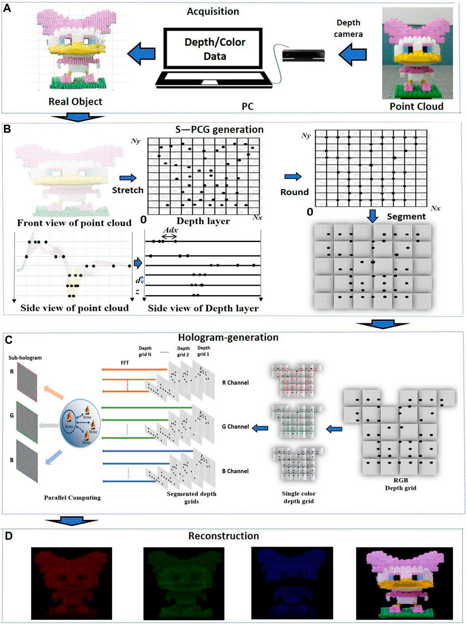
FIGURE 1. Schematic of the system: (A) data acquisition; (B) segmented point cloud gridding generation; (C) hologram generation from efficient depth grids; and (D) reconstruction.
In the first modules, during real object data acquisition, a depth camera is used to capture the depth information and color information to a personal computer (PC). The point cloud models are generated relatively easily from real objects. The depth camera includes an infrared radiation (IR) sensor and a red, green, and blue (RGB) sensor. Depth data are obtained by IR sensor, and color data are collected by RGB sensor. As shown in Figure 1A, point cloud models of the real object are generated from the depth and color data.
In the second module, the point cloud is divided into RGB channels, each point is classified according to depth information grouping and then assigned to a depth grid. Then, the coordinates of the point cloud are stretched to ensure that the hologram has the desired resolution. Depth grids are generated with the hidden point removal (HPR) operator (Katz et al., 2007) to eliminate the repeated value. In each channel, the depth grids are segmented into M × N parts, as shown in Figure 1B.
In the third module, considering the FFT computation of the whole area of the depth grids is a huge waste of calculation time. As shown in Figure 1C. Efficient depth grids are generated from the effective areas. CGHs are generated from efficient depth grids by using Fast Fourier transform (FFT).
In the fourth module, the reconstructed image can be obtained numerically and optically, as shown in Figure 1D. In the numerical simulation, the reconstruction can be calculated by applying the angular spectrum. In the optical experiment, a camera captures the reconstructed image.
2.1 Proposed Method
In the proposed full-color holographic system, data of the real object obtained by the depth camera, we can accurately obtain the distance from each point in the real object to the camera. In this way, combined with the (x, y) coordinates of the point in the color image, we can obtain the 3-D spatial coordinates of each point in the image. The real scene can be restored through the 3-D point cloud model, and the 3-D reconstructed image of the real object can be displayed by computer-generated holography.
Even point clouds usually contain a significant amount of depth information. When a point cloud is generated by a depth camera, the depth interval between each point is constant, as shown in Figures 2A,D. By using depth information, the point clouds are classified into multiple depth layers. The depth layers are resampled and generated to depth grids. Because each point in the depth grid has the same depth, it can be regarded as a pixel in a two-dimensional (2D) image. The depth grid matches each point with the same depth. Owing to the 1,024 × 1,024 grid having up to 1 million node coordinates, the depth grid is sufficient to represent a point cloud with millions of points. The depth information of the point cloud is a finite value when generated from the depth camera. Consequently, the depth grids can be generated from the point-cloud model. Then, the depth grids are segmented into small parts. Only the effective area of the sub-depth grids should be calculated.
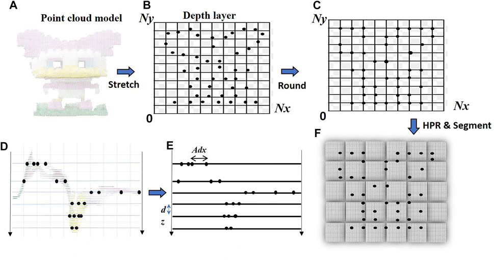
FIGURE 2. The principle of compressed point cloud gridding (S-PCG). (A) A front view and (D) side view of the point cloud model generated using data from a depth camera. (B) A front view and (E) side view of the compressed, stretched, and round process of the sub-layers and (C) the relocated layers. (F) Segmented depth grid generation.
2.1.1 Segmented Point Cloud Gridding Generation
In this study, we propose an S-PCG method to accelerate the full-color CGH generation of real objects. As shown in Figure 2, the proposed method consists of three steps:
1) The stretching factor A is used to stretch the point cloud to match the hologram resolution (Nx × Ny). Here, we select A through the size of the reference object point and the required hologram resolution. We then compress or stretch the point clouds into depth layers, as shown in Figure 2B.
2) A rounding function for depth layers is used to generate all point cloud coordinates with positive integers, as shown in Figure 2C. As shown in Figures 2D–E, before dividing the depth grid, the hidden point removal (HPR) operator is applied to ensure that the pixels of the depth grids have unique values, and then these values will be assigned to the GPU array. A sphere must be created, where viewpoint V is placed at the origin of the sphere, and
where
3) After the HPR process, the depth grids are separated by uniform distances dz, as shown in Figure 2E. The point clouds of real objects are assigned to depth grids according to the depth information. Then, the depth grids are segmented into M × N parts, and separated into RGB channels, as shown in Figure 2F.
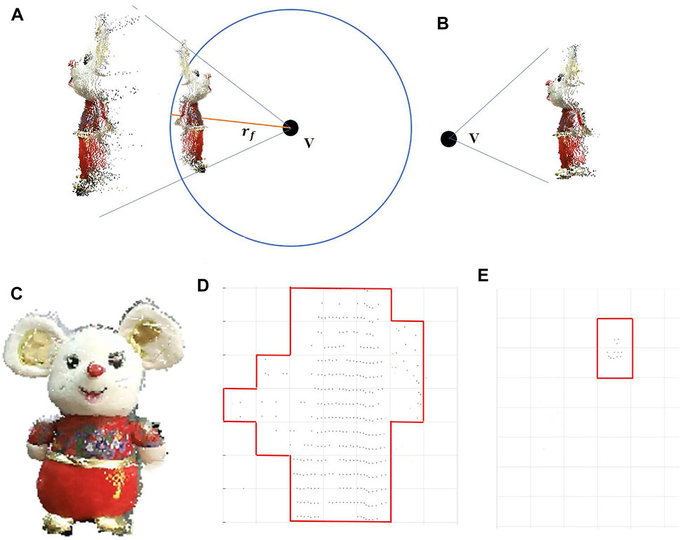
FIGURE 3. Principle of the HPR operator: (A) Spherical flipping of a point cloud using a sphere centered at viewpoint V. (B) Points visible from the viewpoint. The principles of efficient depth grids generation: (C) Point cloud model, (D) data of 200th depth grid and, (E) data of 20th depth grid.
2.1.2 Hologram Generation From Efficient Depth Grids
After the point cloud is divided into sub-depth grids, the grids in each depth are composed as sparse images, as shown in Figures 3C–E. The depth grids can be calculated from the effective area. Because the FFT computation of the entire area of the depth grids is a large waste of calculation time, the region of interest (ROI) operator is adopted for each depth grid to reduce the calculation time.
The ROI for each depth grid is identified after generating the depth grids, the ROI operator is calculated as follows:
where
For hologram generation, full-color CGHs are calculated in RGB channels. The sub-holograms of each depth grid are generated using the angular spectrum method:
where
where z is the distance between the hologram pixel and object points,
Eq. 5 shows the combined RGB hologram
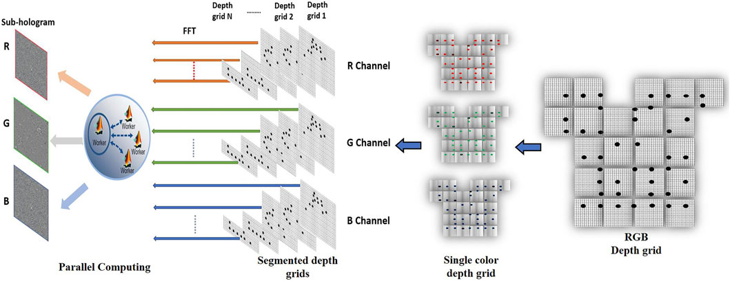
FIGURE 4. The principles of sub-hologram generation from efficient depth grids and RGB hologram combination.
2.3 Calculation Order Analysis of S-PCG Method
To accurately represent real objects, we usually use point clouds, triangles, polygons, and other models to build 3-D objects in the computer. Among them, the point cloud model is the most classic, convenient, and easy to deal with 3-D models. For the point cloud model, even if GPU parallel computing is used, the traditional hologram generation and WRP methods need a lot of computing time. Therefore, a fast algorithm is of great significance to the generation of holograms.
In this section, we compared the time complexities of the WRP method, PCG method, and proposed S-PCG method. Suppose the point cloud consisting of
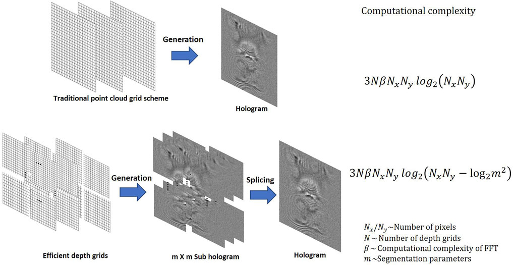
FIGURE 5. The computational complexity of the S-PCG method.
3 Verification and Results
3.1 Numerical Simulation Experiments
The holographic system is working on a Windows 10 64-bit workstation, a GeForce RTX 2060s GPU, a 3.70 GHz Intel Corei9-10900X CPU, and 32 GB RAM. In the system, real objects are captured by a Kinect V2 depth camera, the parameters of this depth camera are shown in Table 1.
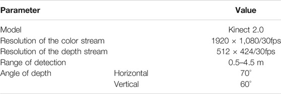
TABLE 1. Parameters of Kinect V2 depth camera.
At first, the WRP method, the R-PCG method and the S-PCG method are compared numerically. The resolution of depth grids and RGB holograms is 1,024 × 1,024 pixels, the pixel size is 7.4 μm. The wavelengths of RGB reference beams are set to 633 nm, 532 nm, and 473 nm, respectively. Figure 6A shows the color images of the real objects; the center of the point cloud model is 350 mm from the cameras. As seen in Figures 6A,B, a case of the experiment is carried out from a real 3-D object, in which a ‘Mouse toy’ consists of 96,074 object points and 247 depth layers. Figures 6C–E show the numerical reconstructed imaged by the WRP method, R-PCG method, and proposed S-PCG method, respectively. The peak signal-to-noise ratios (PSNRs) is applied to evaluate the quality of the reconstructed images. The intensity data of the point cloud served as the reference image. The peak signal-to-noise ratios (PSNRs) of the WRP, R-PCG, and S-PCG methods are 22.9, 23.3, and 23.5 dB, respectively. This confirms that the S-PCG method reconstructs real 3D objects successfully, as do the WRP and R-PCG methods. However, the calculation speed of the proposed method is much faster.
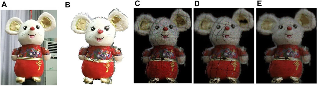
FIGURE 6. (A)Real 3D object and (B) point cloud model of three models. Reconstructed images from (C) WRP method (D) R-PCG method and (E) proposed S-PCG method.
As shown in Figure 7A, the calculation time will decrease exponentially with the number of segmentations because a greater number of segmentations leads to more splicing complexity. In theory, a larger M and N will accelerate the calculation. However, a greater number of segmentations leads to more splicing time. Owing to this result, the relationship between segmentation number and calculation time was determined, as shown in Figure 7A. To balance the computational time and complexity, we selected the segmentation number as 10 × 10. For the traditional R-PCG method, approximately 12.90 and 0.12 s are consumed in central-processing-unit (CPU) and GPU calculation time, respectively. For the proposed S-PCG method, it costs 7.52 and 0.08 s in CPU and GPU calculation time, respectively, corresponding to 58.29 and 66.67% of the time required by the conventional PCG method. As shown in Figures 7B,C, the CPU calculated hologram generation speed is enhanced (92.02–98.58)-fold when comparing the proposed S-PCG method with the WRP method. When a GPU is used, the calculation speed of the S-PCG method is enhanced (39.37–54.11)-fold in comparison with the WRP method at different resolutions. The CPG and GPU calculated hologram generation speed of the S-PCG method are approximately 59% of those of the R-PCG method. As shown in Figure 7D, when the hologram resolution is 2048 × 2048 and the segmentation number is set as 10 × 10, the calculation speed of parallel computing is faster than that of single-pool computing. For more depth grids, parallel pool computing will save more calculation time.
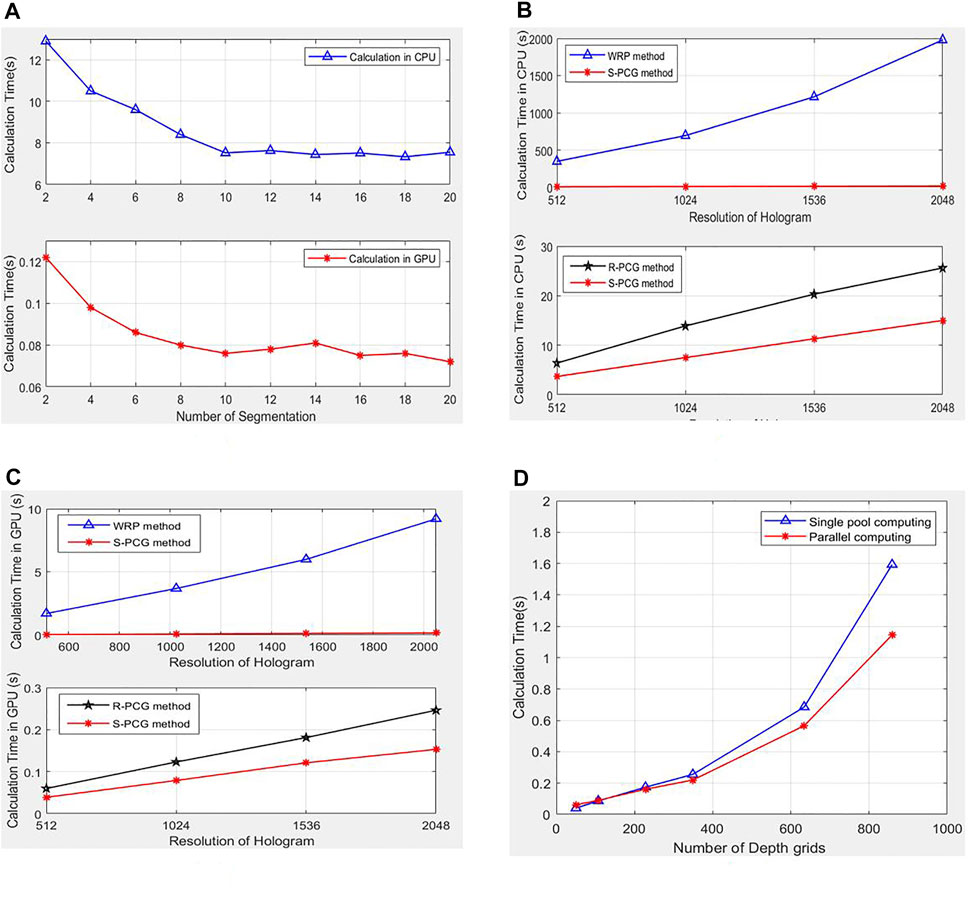
FIGURE 7. (A) The bar graph for comparison of calculation time of the different number of segmentation with S-PCG method. Comparison of CPU (B) and GPU (C) running time of WRP, R-PCG and proposed S-PCG. (D) Comparison of calculation time with single pool and parallel pool.
The CPU and GPU calculation times of the WRP, R-PCG, and S-PCG methods are compared in Table 2. The resolution of the depth grids is 1,024 × 1,024 pixels. Correlation efficiency for WRP position is analyzed to select an acceptable WRP position (Shimobaba et al., 2009). The WRP positions are selected at one times the total depth of the object. The same parameters are used for the CGH calculations.
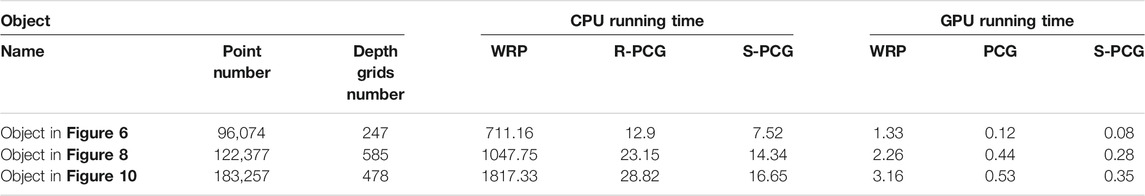
TABLE 2. Calculation time of the full-color holographic system. Running times are in seconds.
Benefiting from the high-performance parallel computing ability of a GPU, the S-PCG method on a GPU generates holograms 47.6–94.0 times faster than those generated on a CPU. Furthermore, applying the S-PCG method with a GPU enhances the speed of hologram generation by a factor of 1.5–1.57 with respect to the R-PCG method and 8.0–16.6 with respect to the WRP method.
As shown in Figure 8, continuous reconstructed images from the person holding a mouse are generated by the S-PCG method in the full-color holographic system. In this experiment, the resolution of the hologram is 2048 × 2048, the depth grids were segmented into 10 × 10 parts, and only the effective areas of the depth grids are calculated. The proposed system can generate holograms from real objects around 1.78 frames per second. The reconstructed distances from the reconstructed plane to the hologram plane are set as 600 and 450 mm, respectively.
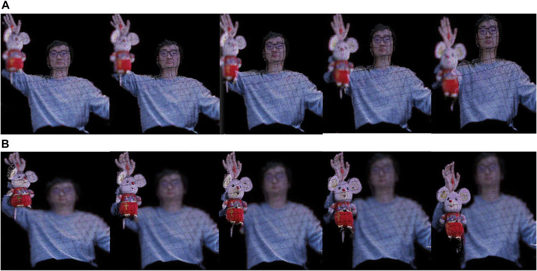
FIGURE 8. Reconstructed images from the S-PCG method with central positions located at (A)600 mm and (B) 450 mm.
3.2 Optical Experiments
Optical reconstructions are performed by using RGB lasers and a transmission-type SLM (7.4 μm, 1,920 × 1,080 pixels). As shown in Figure 9, the RGB lasers are used as reference beams. The output powers and wavelengths are as follows: red laser, 100 mW, and 633 nm; green laser, 100 mW, and 532 nm; and blue laser, 75 mW, and 473 nm.
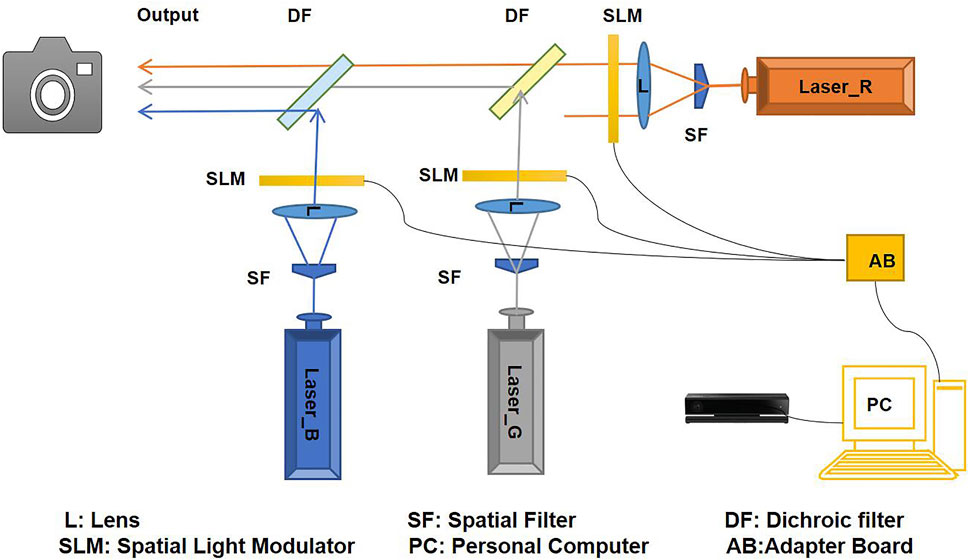
FIGURE 9. The full-color holographic display system.
Figures 10A,B show 2D color images and depth images of the real objects captured by the holographic system. The real object consisting of a person holding a mouse toy was 500 mm from the depth camera. Depth data were acquired from both images to generate the virtual 3-D visualization (point cloud models). Point cloud Figure 10C generated from real object Figure 10A was composed of 183,257 object points, 478 depth grids, and the distance from the center of the SLM to the CCD camera was 500 mm. In the optical experiment, the resolution of the hologram is set as 1,024 × 1,024, the depth grids are segmented into 10 × 10 parts. Numerical and optical reconstructed images are shown in Figure 10D,E. It demonstrates that the real 3D objects were reconstructed successfully with the proposed S-PCG method in the full-color holographic system. It demonstrates that the real 3D objects were reconstructed successfully with the proposed S-PCG method in the full-color holographic system.
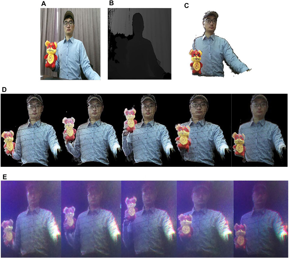
FIGURE 10. (A) Color image and (B) depth image of real objects. (C) Point cloud model and (D) Numerical and (E)optical reconstructed images.
4 Conclusion
In this research, a S-PCG method for a full-color holographic system is proposed to decrease the computational load of generating holographic data. A Kinect depth camera is used to collect the color and depth information from actual scenes, and then point-cloud models are generated from the depth and color data. Object points are categorized into depth grids with identical depth values in RGB channels. In each channel, the depth grids are segmented into M×N parts, and only the effective area of the depth grids will be generated to reduce computational complexity. Compared to the WRP and R-PCG methods, the S-PCG method dramatically decreases the computational complexity of generating holographic data.
Data Availability Statement
The original contributions presented in the study are included in the article/Supplementary Material, further inquiries can be directed to the corresponding author.
Ethics Statement
Written informed consent was obtained from the individual(s) for the publication of any potentially identifiable images or data included in this article.
Author Contributions
YZ: Formulation or evolution of overarching research goals and aims and development or design of methodology. YH and L-MZ: Application of statistical and formal analysis. J-WB and M-YZ: Conducting a research and investigation process. Y-RD and J-RZ: Management activities to annotate.
Funding
This work was supported in part by the Natural Science Foundation of Jiangsu Province (No. BK20200921); and in part by Natural Science Research of Jiangsu Higher Education institutions of China (No. 20KJB510024).
Conflict of Interest
The authors declare that the research was conducted in the absence of any commercial or financial relationships that could be construed as a potential conflict of interest.
Publisher’s Note
All claims expressed in this article are solely those of the authors and do not necessarily represent those of their affiliated organizations, or those of the publisher, the editors and the reviewers. Any product that may be evaluated in this article, orclaim that may be made by its manufacturer, is not guaranteed or endorsed by the publisher.
Supplementary Material
The Supplementary Material for this article can be found online at: https://www.frontiersin.org/articles/10.3389/fphot.2022.831267/full#supplementary-material
References
Cao, H.-K., and Kim, E.-S. (2019). Full-Scale One-Dimensional NLUT Method for Accelerated Generation of Holographic Videos with the Least Memory Capacity. Opt. Express 27 (9), 12673. doi:10.1364/oe.27.012673
Chang, E.-Y., Choi, J., Lee, S., Kwon, S., Yoo, J., Park, M., et al. (2018). 360-Degree Color Hologram Generation for Real 3D Objects. Appl. Opt. 57 (1), A91–A100. doi:10.1364/ao.57.000a91
Chen, N., Lam, E. Y., Poon, T.-C., and Lee, B. (2020). Sectional Hologram Reconstruction through Complex Deconvolution. Opt.LasersEng. 127, 105945. doi:10.1016/j.optlaseng.2019.105945
Katz, S., Tal, A., and Basri, R. (2007). Direct Visibility of Point Sets. ACM Trans. Graph. 26, 2. doi:10.1145/1276377.1276407
Kwon, M.-W., Kim, S.-C., and Kim, E.-S. (2016). Three-Directional Motion-Compensation Mask-Based Novel Look-Up Table on Graphics Processing Units for Video-Rate Generation of Digital Holographic Videos of Three-Dimensional Scenes. Appl. Opt. 55 (3), A22–A31. doi:10.1364/ao.55.000a22
Lee, S. H., Kwon, S. C., Chae, H. B., Park, J. Y., Kang, H. J., and Kim, J. D. K. (2013). Digital Hologram Generation for a Real 3D Object Using by a Depth Camera. J. Phys. Conf. Ser. 415 (1), 012049. doi:10.1088/1742-6596/415/1/012049
Li, G., Hong, K., Yeom, J., Chen, N., Park, J. H., Kim, N., et al. (2014). Acceleration Method for Computer Generated Spherical Hologram Calculation of Real Objects Using Graphics Processing Unit. Chin. Opt. Lett. 12 (6), 010902. doi:10.3788/col201412.060016
Pan, Y., Xu, X., and Liang, X. (2013). Fast Distributed Large-Pixel-Count Hologram Computation Using a GPU Cluster. Appl. Opt. 52 (26), 6562–6571. doi:10.1364/ao.52.006562
Park, J.-H. (2017). Recent Progress in Computer-Generated Holography for Three-Dimensional Scenes. J. Inf. Display 18 (1), 1–12. doi:10.1080/15980316.2016.1255672
Piao, Y.-L., Erdenebat, M.-U., Zhao, Y., Kwon, K.-C., Piao, M.-L., Kang, H., et al. (2020). Improving the Quality of Full-Color Holographic Three-Dimensional Displays Using Depth-Related Multiple Wavefront Recording Planes with Uniform Active Areas. Appl. Opt. 59 (17), 5179–5188. doi:10.1364/ao.387377
Sahin, E., Stoykova, E., Mäkinen, J., and Gotchev, A. (2020). ComputerGenerated Holograms for 3D Imaging: A Survey. ACM Comput. Surv. (Csur) 53 (2), 1–35. doi:10.1145/3378444
Shimobaba, T., Masuda, N., and Ito, T. (2009). Simple and Fast Calculation Algorithm for Computer-Generated Hologram with Wavefront Recording Plane. Opt. Lett. 34 (20), 3133–3135. doi:10.1364/ol.34.003133
Sifatul Islam, M., Piao, Y.-L., Zhao, Y., Kwon, K.-C., Cho, E., and Kim, N. (2020). Max-Depth-Range Technique for Faster Full-Color Hologram Generation. Appl. Opt. 59 (10), 3156–3164. doi:10.1364/ao.383946
Takenaka, M., Kakue, T., Shimobaba, T., and Ito, T. (2021). Interactive Holographic Display for Real-Time Drawing and Erasing of 3D Point-Cloud Images with a Fingertip. IEEE Access 9, 36766–36774. doi:10.1109/access.2021.3062877
Wang, J., Wang, Q.-H., and Hu, Y. (2017). Fast Diffraction Calculation of Cylindrical Computer Generated Hologram Based on Outside-In Propagation Model. Opt. Commun. 403, 296–303. doi:10.1016/j.optcom.2017.07.045
Wu, H. Y., Shin, C. W., and Kim, N. (2019). “Full-color Holographic Optical Elements for Augmented Reality Display,” in Holographic Materials and Applications. Editor M. Kumar (London, United Kingdom: IntechOpen). Chap. 3.25. doi:10.5772/intechopen.85767
Yamaguchi, M., Wakunami, K., and Inaniwa, M. (2014). Computer Generated Hologram from Full-Parallax 3D Image Data Captured by Scanning Vertical Camera Array (Invited Paper). Chin. Opt. Lett. 12 (6), 060018. doi:10.3788/col201412.060018
Yeom, J., Jang, C., Hong, J., and Lee, B. (2014). Full-color Lens-Array Holographic Optical Element for Three-Dimensional Optical See-Through Augmented Reality. Opt. Lett. 39 (1), 127–130. doi:10.1364/OL.39.000127
Zhao, Y., Piao, M.-l., Li, G., and Kim, N. (2015). Fast Calculation Method of Computer-Generated Cylindrical Hologram Using Wave-Front Recording Surface. Opt. Lett. 40 (13), 3017–3020. doi:10.1364/ol.40.003017
Zhao, Y., Cao, L., Zhang, H., Tan, W., Wu, S., Wang, Z., et al. (2016). Time-Division Multiplexing Holographic Display Using Angular-Spectrum Layer-Oriented Method (Invited Paper). Chin. Opt. Lett. 14 (1)–10009. doi:10.3788/col201614.010005
Zhao, T., Liu, J., Gao, Q., He, P., Han, Y., and Wang, Y. (2018). Accelerating Computation of CGH Using Symmetric Compressed Look-Up-Table in Color Holographic Display. Opt. Express 26 (13), 16063. doi:10.1364/oe.26.016063
Zhao, Y., Shi, C.-X., Kwon, K.-C., Piao, Y.-L., Piao, M.-L., and Kim, N. (2018). Fast Calculation Method of Computer-Generated Hologram Using a Depth Camera with point Cloud Gridding. Opt. Commun. 411, 166–169. doi:10.1016/j.optcom.2017.11.040
Zhao, Y., Kwon, K.-C., Erdenebat, M.-U., Islam, M.-S., Jeon, S.-H., and Kim, N. (2018). Quality Enhancement and GPU Acceleration for a Full-Color Holographic System Using a Relocated point Cloud Gridding Method. Appl. Opt. 57, 4253. doi:10.1364/ao.57.004253
Zhao, Y., Erdenebat, M.-U., Alam, M.-S., Piao, M.-L., Jeon, S.-H., and Kim, N. (2019). Multiple-Camera Holographic System Featuring Efficient Depth Grids for Representation of Real 3D Objects. Appl. Opt. 58 (5), A242–A250. doi:10.1364/ao.58.00a242
Keywords: computer generated holography, color holography, three-dimensional image processing, real objects, holographic system
Citation: Zhao Y, Huang Y, Zhu L-M, Bu J-W, Du Y-R, Zhu M-Y and Zhu J-R (2022) Segmented Point Cloud Gridding Method for a Full-Color Holographic System With Real Objects. Front. Photonics 3:831267. doi: 10.3389/fphot.2022.831267
Received: 08 December 2021; Accepted: 20 January 2022;
Published: 21 February 2022.
Edited by:
Ni Chen, King Abdullah University of Science and Technology, Saudi ArabiaReviewed by:
Zhenbo Ren, Northwestern Polytechnical University, ChinaTakashi Kakue, Chiba University, Japan
Copyright © 2022 Zhao, Huang, Zhu, Bu, Du, Zhu and Zhu. This is an open-access article distributed under the terms of the Creative Commons Attribution License (CC BY). The use, distribution or reproduction in other forums is permitted, provided the original author(s) and the copyright owner(s) are credited and that the original publication in this journal is cited, in accordance with accepted academic practice. No use, distribution or reproduction is permitted which does not comply with these terms.
*Correspondence: Yu Zhao, emhhb3l1QHl6dS5lZHUuY24=