- 1Institute of Computational Biology, Helmholtz Zentrum München, Munich, Germany
- 2Comprehensive Pneumology Center, Member of the German Center for Lung Research, Munich, Germany
- 3Institute of Lung Biology and Disease, Helmholtz Zentrum München, Munich, Germany
- 4Mechanical Engineering Department, Amirkabir University of Technology, Tehran, Iran
- 5Department of Otorhinolaryngology, Head and Neck Surgery, Medical Center of Heidelberg University, Heidelberg, Germany
- 6Department of Mechanical Engineering, Faculty of Engineering, University of Alberta, Edmonton, AB, Canada
- 7Institute of Fundamental and Frontier Sciences, University of Electronics and Technology of China, Chengdu, China
- 8Department of Biology, Ludwig-Maximilians University Munich, Munich, Germany
- 9German Center for Diabetes Research (DZD e.V.), Munich, Germany
The nasal olfactory region is a potential route for non-invasive delivery of drugs directly from the nasal epithelium to the brain, bypassing the often impermeable blood-brain barrier. However, efficient aerosol delivery to the olfactory region is challenging due to its location in the nose. Here we explore aerosol delivery with bi-directional pulsatile flow conditions for targeted drug delivery to the olfactory region using a computational fluid dynamics (CFD) model on the patient-specific nasal geometry. Aerosols with aerodynamic diameter of 1 µm, which is large enough for delivery of large enough drug doses and yet potentially small enough for non-inertial aerosol deposition due to, e.g., particle diffusion and flow oscillations, is inhaled for 1.98 s through one nostril and exhaled through the other one. The bi-directional aerosol delivery with steady flow rate of 4 L/min results in deposition efficiencies (DEs) of 50.9 and 0.48% in the nasal cavity and olfactory region, respectively. Pulsatile flow with average flow rate of 4 L/min (frequency: 45 Hz) reduces these values to 34.4 and 0.12%, respectively, and it mitigates the non-uniformity of right-left deposition in both the cavity (from 1.77- to 1.33-fold) and the olfactory region (from 624- to 53.2-fold). The average drug dose deposited in the nasal cavity and the olfactory epithelium region is very similar in the right nasal cavity independent of pulsation conditions (inhalation side). In contrast, the local aerosol dose in the olfactory region of the left side is at least 100-fold lower than that in the nasal cavity independent of pulsation condition. Hence, while pulsatile flow reduces the right-left (inhalation-exhalation) imbalance, it is not able to overcome it. However, the inhalation side (even with pulsation) allows for relatively high olfactory epithelium drug doses per area reaching the same level as in the total nasal cavity. Due to the relatively low drug deposition in olfactory region on the exhalation side, this allows either very efficient targeting of the inhalation side, or uniform drug delivery by performing bidirectional flow first from the one and then from the other side of the nose.
1 Introduction
The nasal olfactory region is a potential non-invasive path for drug delivery to the brain for neurological disorders which by-passes the blood-brain barrier (BBB) (Frey et al., 1997; Mistry et al., 2009). Conventional nasal sprays provide large particles (>50 µm) which mainly deposit in the nasal valve and vestibule regions due to inertial impaction (Inthavong et al., 2011). Only a small fraction of spray aerosol passing through the anterior parts of the nasal cavity reaches the posterior region, where it either deposits in the lower parts of the nasal cavity or the turbinate regions (Cheng et al., 2001; Djupesland and Skretting, 2012), or it exits the nasal cavity into the nasopharyngeal region. Since the olfactory region is located in the upper posterior region, particles from conventional nasal sprays do not reach the olfactory region efficiently (Djupesland, 2013; Chen et al., 2020). This raises interest in new methods for targeting the olfactory.
It has been shown that nanoparticles are potentially more effective for aerosolized drug delivery to the nasal epithelium of the olfactory region than micron-sized particles. Several studies investigated the nose to brain delivery by transporting the drug-laden chitosan nanoparticles into the olfactory region (Alam et al., 2012; Chen et al., 2012; Fazil et al., 2012). Nanoparticle (<100 nm diameter, dp) delivery is considered potentially useful, since their diffusivity enhances aerosol transport into non- or poorly ventilated regions such as the olfactory epithelium region. In spite of this advantage, there are also severe limitations for nano-sized therapeutic aerosol. The main limitation arises from the cubic dependence of aerosol volume on particle diameter, which makes it difficult to deliver sufficiently high drug doses for therapeutic efficacy in patients with nanosized-sized aerosol. This becomes evident when considering that typically used 3 µm therapeutic aerosol has a 2.7 × 10⁴ fold higher drug (mass) dose than the same number concentration of 100 nm aerosol. Compensation of this drug loading deficiency would require a 2.7 × 10⁴ fold increase in 100 nm aerosol concentration (as compared to 3 µm aerosol). However, the resulting extremely high aerosol number concentrations (>1010 particle per cm3) would induce aerosol coagulation and thus an increase in aerosol size mitigating the desired diffusion-driven enhanced deposition efficiency in the olfactory region (Hinds, 1999).
Among the microparticles, the very fine particles (close to dp = 1 µm) are preferred for olfactory aerosol delivery due to their relatively low relaxation time and high diffusivity which means that these particles follow the streamlines of the air flow (low impaction) and thus reach the olfactory region more than larger particles, where they experience enhanced deposition due to diffusion (Shi et al., 2006; Shi et al., 2007; Si et al., 2013). To overcome these limitations we investigate the potential of clinically already established pulsatile aerosol, in which the inhaled aerosol flow is superimposed with pressure oscillations resulting in enhanced ventilation and subsequently aerosol delivery to non- or poorly ventilated regions of the nose such as maxillary sinuses (Möller et al., 2014). Upon induction of pulsatile pressure in this cavity a standing pressure wave is formed, which results in cyclic flow into cavity at the resonance frequency of the cavity. Möller et al. (2014) have shown that while nasal sprays do not reach the non-ventilated paranasal sinuses, pulsatile aerosol devices such as the PARI SINUS nebulizer (PARI GmbH, Starnberg, Germany; mass median aerodynamic diameter, MMAD = 3 µm; pulsation frequency 45 Hz), or the DTF Aerodrug (Tours, France; MMAD = 3 µm; 100 Hz) deliver approximately 5% of the nebulized dose to the paranasal sinuses. Since the olfactory region is also a poorly ventilated region in the upper nasal cavity, it is conceivable that aerosol delivery with pulsatile flow may enhance aerosol transport onto the epithelium of the olfactory region.
Bi-directional aerosol delivery methods are recently used to improve the deposition efficiency in the nasal cavity (Djupesland and Skretting, 2012; Xi et al., 2017). In contrast to normal (bilateral) inhalation during both nostrils, in bi-directional air flow technique (aerosol-laden) air flow is pushed with a pump into one nostril, flows to the end of the nasal cavity (nasopharynx), turns around into the other nasal cavity, and finally exits through the other nostril. This requires closing the soft palate (Figure 1), which separates the nasal from the oropharyngeal cavity. This can be accomplished by pushing the back part of the tongue towards the upper part of the oropharynx, while keeping the mouth open. As bi-directional flow constrains aerosol flow to the nose particle deposition in extranasal regions is prevented and particle deposition efficiency (DE) in the main nasal cavity is enhanced (Xi et al., 2018). During this process a certain fraction of the aerosol particles will deposit on the nasal wall—the rest is exiting the nasal cavity (Farnoud et al., 2020a). Bidirectional flow can also be established using devices such as the OptiNose (OptiNose AS; Oslo, Norway), which directs exhaled air from the mouth to the nostrils via a mouthpiece connected to a nasal interface (Djupesland and Skretting, 2012). An advantage of OptiNose as compared to inhalation-based nasal delivery systems (e.g., the PARI SINUS) is that during exhalation the soft palate is automatically closed. Thus, the patient does not have to learn how to close the soft palate, the OptiNose automatically enables bi-directional aerosol flow confined to the nose (Djupesland et al., 2006; Djupesland and Skretting, 2012; Farnoud et al., 2020a).
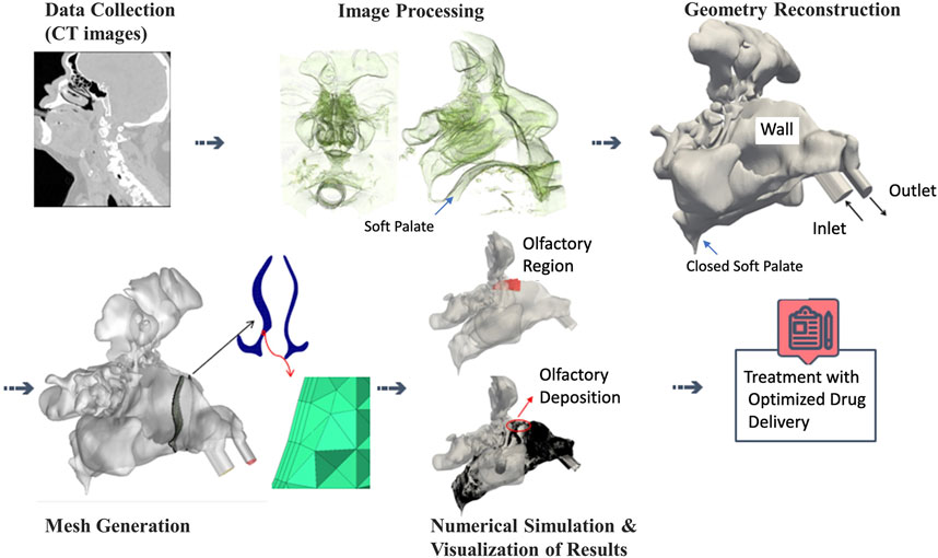
FIGURE 1. The workflow for modeling of patient-specific olfactory drug delivery starting from acquisition of CT images over geometry reconstruction and mesh generation to numerical simulation and visualization of particle-laden air flow (Farnoud et al., 2020a). For bi-directional aerosol flow, the soft palate needs to be closed, which is illustrated in top panels.
Bi-directional nasal aerosol deposition has not been studied extensively, but some experimental and numerical studies are available (Kleven et al., 2005; Xi et al., 2018; Hosseini and Golshahi, 2019). Xi et al. showed both experimentally and numerically that bi-directional nasal drug delivery enhances the deposition of particles in the upper portion of the nasal cavity (Xi et al., 2018), especially in the olfactory region (Xi et al., 2017). Due to the relatively poor ventilation of that part of the nasal cavity which is in close proximity to the epithelium of the olfactory region, the diffusive nature of nanoparticles (<100 nm diameter) may provide a means for enhanced drug delivery to the olfactory epithelium. While nanoparticles have also been explored with bi-directional administration for targeting the olfactory region (Tian et al., 2017), use of nanoparticles does not allow large aerosol mass doses to be inhaled. Hence, in the present study we explore the size range between traditional aerosol for pulmonary drug delivery (3–5 µm diameter) and nanoparticles, namely 1 µm particles, for its capacity of enhanced drug delivery to the olfactory region.
The present computational fluid dynamics study investigates the regional deposition pattern and DE of 1 µm particles in the entire nasal airway, and specifically in the olfactory region, during bi-directional delivery into realistic nasal geometry. Two-way coupling between particles and air flow are considered and flow partitioning in the olfactory region and the effect of aerosol pulsation on olfactory drug delivery are analyzed. Since the local drug dose per area determines the therapeutic efficacy of a drug, in this study regional dose in the nasal cavity and specifically olfactory region is investigated as mass per area. Moreover, dose and DE in right and left cavity and olfactory regions are compared for pulsatile and non-pulsatile inlet flow conditions.
2 Methodology
A three-dimensional geometry of the nasal cavity and paranasal sinuses was reconstructed from CT images of a male, 82-year-old patient, as previously studied by Farnoud et al. (2017), Farnoud et al. (2020a), and Farnoud et al. (2020b). The CT images were segmented using the open source software package 3DSlicer. The paranasal sinuses are healthy and the diameters of right and left ostia are 4.58 and 5.45 mm. The software package of ICEM-CFD (Ansys) was used for the volume grid generation. Here approximately 20 million unstructured tetrahedral cells with 3 prism layers were generated, which is required to capture correct large eddy simulations (LES) as well as particle deposition on the wall. The patient was asked to keep his mouth open by holding a pipe between his teeth during CT imaging; therefore, the three-dimensional geometry represents the realistic closed soft palate condition which is ideal for bi-directional drug delivery in nasal cavity. Following recommendations from the literature, and the manual of the devices such as PARI SINUS nebulizer, two clockwise 45° nosepieces were connected to the nostrils (Farnoud et al., 2020a). Figure 1 illustrates the workflow for CT-based simulation and visualization of particle-laden airflow inside nasal cavity.
2.1 Governing Equations
2.1.1 Continuous Phase Equations
In the present model, the three-dimensional, incompressible unsteady Navier-Stokes equations in isothermal condition are discretized and numerically solved. A LES turbulence model is implemented for simulation of the fluid flow which may be laminar, transitional, or turbulent. Furthermore, a two-phase flow model was used for considering the interaction between airflow and particles.
The three-dimensional unsteady flow field inside the nasal airway is governed by the isothermal filtered incompressible Navier-Stokes equations as:
where implicit grid filter operator
The LES turbulence model adds
The values of
The difference between the turbulent sub-grid dynamic stress tensor and turbulent SGS tensor is described by Germano identity:
where
where
In addition to the filtered Navier-Stokes equations, an equation for the conservation of the passive scalar which is entering from the inlet as follows:
where c is the concentration of the passive scalar that enters the computational domain through the right nosepiece.
2.1.2 Dispersed Phase Equations
The Lagrangian solver at time t calculates a total number of N computational particles (parcels) as
In these equations
where
Although the true value of the instantaneous gas velocity seen by the particle can only be obtained by direct numerical solution (DNS), the effect of the modeled fluctuations will be negligible due to the very fine grid used in the present work, and therefore, the value of
In each time step the source term
2.2 Numerical Methods
The open-source software package of OpenFOAM (www.openfoam.org) is used to numerically solve the particle-laden flow equations inside the nasal airway. The Pressure-Implicit with Splitting of Operators (PISO) method combined with Semi-Implicit Method for Pressure-Linked Equations (SIMPLE) algorithm (pimpleFoam solver) is used for the solution of the Eulerian phase and the Lagrangian Intermediate library is combined with the pimpleFoam solver to enable the solution of the secondary phase in the gas phase (Patankar and Spalding, 1972; Patankar, 1980; Syrakos et al., 2017). The pimpleFoam solver is suitable for LES simulations with the local dynamic k-equation sub-grid scales (SGS) model. The local dynamic k-equation SGS model is used since it covers the laminar-transitional-turbulent region so that it is very suitable for the simulation of the present work which is predominantly laminar with possible transitional and turbulent flow regimes. It is important to note that in the local dynamic k-equation SGS model,
The diffusion terms are discretized with the least-squares scheme, which is second-order accurate on general unstructured meshes (Martínez et al., 2015). Since upwind-dominated schemes could lead to numerical dissipations in orders of SGS viscosity dissipation and consequently decrease the precision of the numerical simulations (Sweby, 1984), the convection term in the momentum equation requires a proper discretization scheme. In the present work, “Gauss filteredLinear” scheme, which is a low-dissipation second-order central differencing method, is implemented for LES. The convection term of other (scalar) quantities is discretized by the second-order “Gauss limitedLinear” scheme based on Total Variation Diminishing (TVD) (Moukalled et al., 2016). The time derivatives are discretized by the Second-Order Upwind Euler (SOUE) scheme (Wang et al., 2009).
Based on Figure 1, the nasal cavity is divided into three main parts: the wall, inlet, and outlet. The nosepieces are extended to represent the fully developed condition (Shi et al., 2007). The sinusoidal and steady air flow profiles are implemented for the velocity at the inlet by a Dirichlet boundary conditions. The air velocity for both inlet conditions represents an average flow rate of 4 L/min. The velocity profile of the gas phase is described as
where
Here, 1 µm particles are considered with an average flow rate of 4 L/min. Moreover, pulsatile aerosol delivery is compared with non-pulsatile (steady) inlet airflow carrying particles with a diameter of 1 µm. As mentioned above, this particle size is used due to its relatively low relaxation time and high diffusivity which means that particles follow the streamlines (low impaction) and reach the olfactory region where they can deposit due to diffusion more than larger particles. This concept also rationalizes the choice of a relatively low flow rate of 4 L/min, since this reduces impaction in bends like vestibule and nasal valve and enhances the residence time and thus diffusive deposition of the particles in the olfactory region. The particles were distributed randomly and uniformly across the inlet plane and the velocities of the particles at the inlet are equal to the instantaneous velocity of the gas phase at the specific time and location of each particle. It is assumed that the particles stick to the wall once they touch it. The particles are followed until they hit the wall or reach the outlet and escape the computational domain. Although aerosol injection ceases after 0.5 s, the computational simulation is continued for 1.98 s to ensure that all particles have either deposited or exited the domain. The simulations are performed using 256 CPUs and the time steps were variably chosen based on the Courant number criteria to be lower than 1 which led to time steps in a range of 10−5 s to 10−6 s.
3 Results and Discussion
3.1 Model Validation for Regular (Bilateral) Inhalation
The validity of the present numerical solver was assessed in two steps. In our previous publications (Farnoud et al., 2017; Farnoud et al., 2020a; Farnoud et al., 2020b), the DE in 90° bends was compared to the experimental data of Pui et al. (1987) and other research in the literature (Breuer et al., 2006; Nicolaou and Zaki, 2016; Inthavong, 2019) to ensure that the solver is able to capture the DE of particles correctly. This benchmark is a popular approach to validate the capability of a numerical solver to predict particle deposition in curvature geometries.
In the next step, our model was compared to experimental and numerical data obtained for other nasal passages. Since the majority of the experimental and numerical studies on nasal aerosol delivery have focused on bilateral aerosol delivery, we validated our computational model with experimental DE data from a different nasal passage with bilateral drug delivery condition. Thus, for the current nasal passage geometry with bilateral air flow (drug delivery), open soft palate and delivery through both nostrils, DE is calculated as a function of the characteristic impaction parameter (
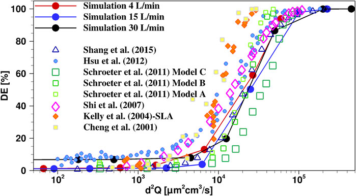
FIGURE 2. Comparison of present “simulation” results with experimental (Cheng et al., 2001; Kelly et al., 2004; Schroeter et al., 2011; Hsu and Chuang, 2012) and numerical (Shi et al., 2007; Shang et al., 2015) studies in literature from different realistic nasal geometries and similar boundary and initial conditions. The 1 µm case is represented by the lowest d2Q value for each of the flow rate curves.
3.2 Mesh Quality Control
The result of large eddy simulation (LES) is highly dependent on the quality and resolution of the computational grid. To determine the resolution and quality of a LES simulation various criteria, typically referred to as “LES indices of Resolution Quality” (LES_IQk), have been introduced. One LES_IQk is defined as the ratio of resolved turbulent kinetic energy (TKE) to the total TKE, and can be formulated as:
where
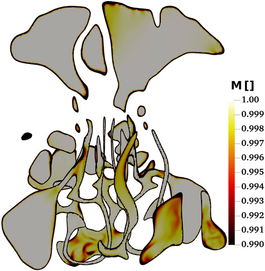
FIGURE 3. The contour plots of ratio of resolved turbulent kinetic energy (TKE) to total TKE as a control for the mesh quality of the present large eddy simulations (LES) study.
3.3 Profiles of Bi-Directional, (Non-)Pulsatile Air Flow
In the present study, the effect of bi-directional pulsatile inlet airflow on the deposition pattern of the particles in the nasal airway, and specifically the olfactory epithelium region, is investigated. Since the inlet airflow profile directly affects dispersion and deposition of the particles, pulsating and non-pulsating airflow conditions are implemented at the inlet to assess the effect of the pulsation on the airflow pattern inside the nasal airway and specially the olfactory region.
Figure 4 shows the streamlines of the air with non-pulsatile (constant) inlet flow rate of 4 L/min which are colored by normal velocity (normalized to average air speed at the inlet, i.e., right nostril). The simulations are performed until t = 1.98 s and Figure 4 represents the results at this time. Different regions of the nasal anatomy are shown in the bottom panel of Figure 4 to enable the further discussion based on the regions in the nasal cavity. At the right vestibule, a recirculation zone is observed and swirling flows occur as the air passes through the nasal valve. At the upper parts of the nasal valve (Figure 4. Top left panel) a swirling flow is observed which moves downwards to the inferior right meatus. The air flow from the nasal valve is divided into three meatuses and some streamlines move towards the top of the nasal cavity and pass through the olfactory region with relatively high velocity. At the nasopharynx the airflows from the three meatuses mix and make a 180° turn while entering the left cavity. At the left cavity, the flow moves from the nasopharynx towards the left nostril and uniform streamlines are observed in the entire main nasal airway except for the right vestibule where a recirculation zone is observed. In both right (entering) and left (exiting) vestibules recirculation zones are observed. The air velocity at the left vestibule increases since the upstream airflow encounters a sudden contraction in the nasal valve region.
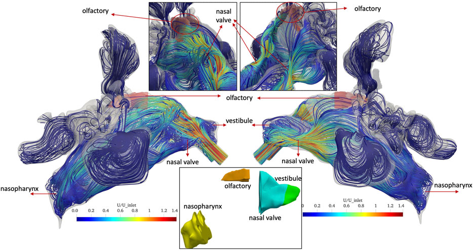
FIGURE 4. Streamlines of the normal(-ized) air velocity U in the nasal cavity for non-pulsatile (constant) inlet flow of 4 L/min at the end of inhalation period (t = 1.98 s). Right (inlet) and left (exit) views and close-up views of the olfactory region (shaded in red) are given in the left and right panel, respectively. In the bottom panel, different regions of the nasal anatomy are shown.
Similarly, Figure 5 shows the streamlines of the normal velocity in the nasal cavity and olfactory region at T/2 of the last air flow pulse for the pulsatile inlet airflow with average flow rate of 4 L/min and frequency of 45 Hz (oscillation period: T = 22.2 ms). A complex airflow pattern including recirculation zones and swirling flows are observed in the anterior parts of both right and left main nasal airway due to periodical pulses in the airflow. For both inlet airflow conditions, the maximum velocity is observed in the anterior region and is close to 1.4 times the average inlet velocity. In contrast, streamlines with higher velocities pass through the right olfactory region when the non-pulsatile airflow is implemented at the inlet. The pulsatile airflow at the inlet avoids the impingement of the airflow to the top of the cavity after the nasal valve, which results in streamlines with much lower velocity passing the olfactory region.
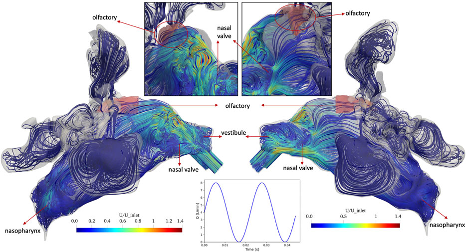
FIGURE 5. Streamlines of the normal(-ized) air velocity U in the nasal cavity for pulsatile inlet flow of 4 L/min with a frequency of 45 Hz (oscillation period T = 22.2 ms) at T/2 of the last modeled pulse (t = 1.98 s), where T/2 (middle of cycle of air flow pulsation) represents the condition where the inlet flow is equal to the average flow rate of the pulsatile flow profile. Again, the olfactory epithelium region is shaded in red.
Since the streamlines only show the flow pattern and not the amount of the air reaching to each region, the airflow fraction in the right and left olfactory regions are calculated. For this purpose, a new variable, the concentration of a passive scalar tracer (C), is introduced in the OpenFOAM code. C is initially 0 in the nasal cavity but changes to 1 when the drug-laden air flow reaches the specific computational cell. Analogous to a gaseous tracer, once all of the initially present air in the nasal cavity is replaced by the inhaled air, C = 1 throughout the nasal cavity. Hence, C reflects the fractional replacement of the initially present air with the inhaled air (drug-laden air fraction). The variable C is calculated in the whole domain including non-convectively ventilated paranasal sinuses and the olfactory region.
Figure 6 shows the contour plots of the variable C and the streamlines of the air flow (at the end of inhalation period t = 1.98 s) colored by variable C in different regions of the nasal cavity specifically in the olfactory region for non-pulsatile inlet airflow condition. It is noteworthy that C is larger than zero even in some regions of the non-ventilated paranasal sinuses (Figure 6, top), which is due to diffusional (not convective) transport of inhaled air into these regions. Moreover, Figure 6 (bottom) depicts the iso-volumes (regions that represent a specific value of a parameter) of variable C for values more than 0.99 which means 99% of these regions are filled with inhaled air indicating that these regions can be readily reached by the inhaled air either via convection or via diffusion. As even the lowest iso-volumes of C = 97.67% in the left nasal valve and vestibule are close to 100%, gas exchange in the entire nasal cavity (including olfactory epithelium region) is highly effective for a 1.98 s inhalation (bottom panel and pie chart in Figure 6). This implies that also olfactorially relevant gas molecules carried by the inhaled air will be able to efficiently reach the olfactory epithelium, which is a prerequisite for the sense of smell to work properly. For fine particles with low relaxation time and high diffusivity, the same statement is valid.
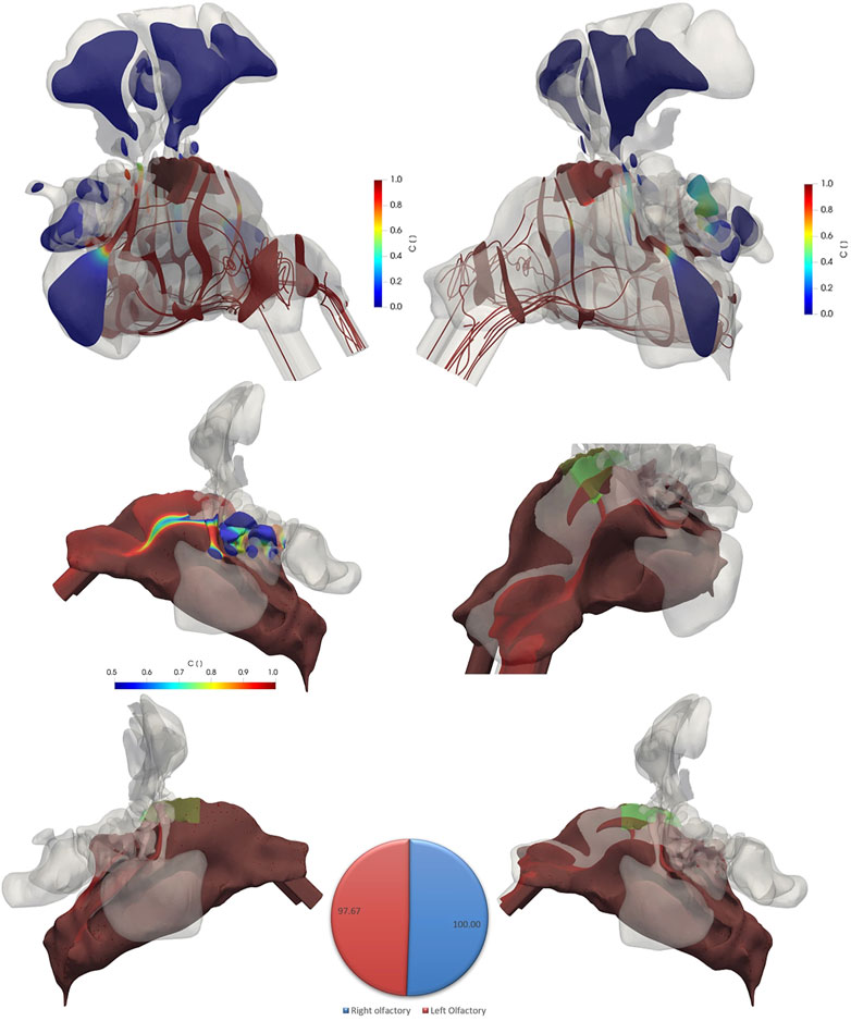
FIGURE 6. The contour plots of variable C (drug-laden air fraction) and flow streamlines (color coded for C) in different regions of the nasal cavity specifically in the olfactory region (green shaded) at t = 1.98 s (end of delivery phase) for the non-pulsatile inlet flow rate of 4 L/min (top figures). The figures at the bottom show the iso-volumes of variable C for values more than 0.99 from left and right views as well as close-up view of the left cavity. An iso-volume of variable C with values more than 0.5 is shown in the middle figure for a better visualization of values. The Pie chart shows the volume weighted value of C in the left and right olfactory regions. The green shaded regions in the bottom figures represent the olfactory region.
There are considerable similarities and some differences between pulsatile flow (Figure 7) and non-pulsatile flow profile (Figure 6) when comparing the passive scaler tracer contours. Air exchange in the olfactory region and the entire nasal cavity is virtually identical and almost complete (>97%) for both cases (bottom panel and pie chart in Figures 6, 7). One notable difference is the lower ventilation (lower C values) in the left cavity specifically at the nasal valve and vestibule region (Figure 7, bottom right) when pulsatile airflow is used. Moreover, the pattern of the streamlines after the nasal valve is more straight for the non-pulsatile condition. However, in the pulsatile airflow simulations, the streamlines are oriented into all directions due to the disturbance caused by pulsatile airflow pattern.
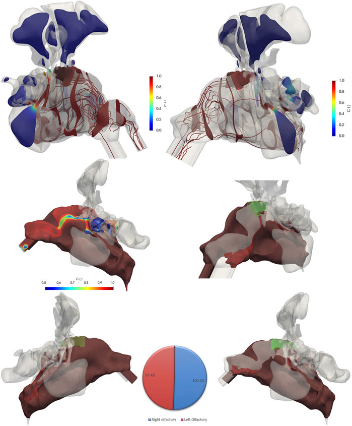
FIGURE 7. The contour plots of variable C (drug-laden air fraction) and flow streamlines (color coded for C) in different regions of the nasal cavity specifically in the olfactory region (green shaded) at t = 1.98 s for pulsatile inlet flow of 4 L/min and frequency of 45 Hz. While the drug-laden air fraction is virtually identical to that of the non-pulsatile conditions (bottom and pie chart), the streamlines in pulsatile airflow have more complex structure after the nasal valve moving the air to different directions and streamlines of the non-pulsatile airflow moving straight after the nasal valve. The iso-volumes of variable C for values more than 0.99 from left and right views as well as close-up view of the left cavity are shown at the bottom. An iso-volume of variable C with values more than 0.5 is shown in the middle figure for a better visualization of values.
A more detailed view on the olfactory region is presented in Figure 8. The fractional air flow in/through the left and right olfactory region at the end of the modeling period (t = 1.98 s) is 0.703 and 0.653% (of inhaled particle dose) independent of pulsation state, respectively, which is due to the slight differences in geometry and volume (left: 337 mm3; right: 331 mm3). Hence, from this perspective the conditions for relatively uniform left/right aerosol deposition in the olfactory epithelium region are favorable. This will be discussed in more detail in the next section.
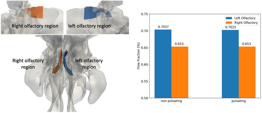
FIGURE 8. The geometry of the right (blue) and left (orange) olfactory regions (left figures) and the corresponding fraction of drug-laden airflow for non-pulsatile and pulsatile inlet airflow conditions (right plot) at the end of the inhalation phase (t = 1.98 s). The geometries of the olfactory regions are shown both from the side (top left) and the top (bottom left). The observed difference between flow fraction in the left and right olfactory region is due to corresponding differences in the left and right volume of the olfactory epithelium region, respectively.
3.4 Particles
Four million computational particles (parcels) with diameters of 1 µm are introduced for 0.5 s from the right nostril (at the velocity of the air at the nostril) and carried by non-pulsatile and pulsatile airflows (4 L/min) to the left nostril, which led to deposition of the particles in different regions of the cavity or to their exit through the left nostril. These bi-directional flow simulations are performed for a duration of 1.98 s to ensure that all particles have deposited or exited the nasal domain. Particle deposition patterns and DEs in the right and left nasal passages and olfactory regions are visualized and quantitatively evaluated at 1.98 s as presented below.
Figure 9 illustrates the spatial deposition pattern of 1 µm particles for either non-pulsatile (top) or pulsatile (bottom) inlet airflow in the nasal airway and olfactory region (highlighted). The main deposition occurs in the right nasal cavity and specifically in the regions with uneven surfaces which cause changes in the direction of the flow and consequently deposition of particles due to inertial impaction.
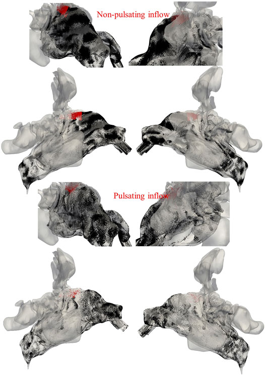
FIGURE 9. Deposition pattern of 1 µm particles (black spots) for non-pulsatile (top) and pulsatile inlet airflows (bottom). The particles deposited in the olfactory region are indicated by red color. Left and right panels refer to views onto the right and left side of the nasal cavity, respectively.
Quantitative analysis of our model reveals that total (1 µm) particle deposition in the nose is 50.9 and 34.4% for aerosol delivery with non-pulsatile and pulsatile bi-directional 4 L/min air flow, respectively (Figure 10). This is significantly larger than the corresponding value for bilateral inhalation (1.25%) indicating that during normal inhalation there is almost no impaction in the nasal cavity, while for bi-directional flow the sudden change in flow direction in the nasopharynx region induces significant impaction of 1 µm particles. In bilateral aerosol delivery (injection from both nostrils) particles mainly escape the nasal passage from the nasopharynx to the pharynx. However, during bi-directional delivery, particles enter from one nostril and exit from the other one which leads to substantial enhancement of DE in the nasal cavity.
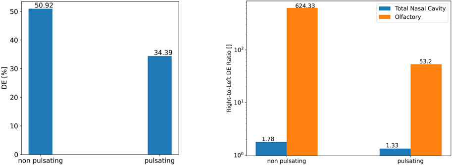
FIGURE 10. The role of pulsation on 1 µm particle deposition efficiency in the entire nasal cavity (left) and the right and left olfactory region (right: note: log scale).
For further validation of particle deposition modeling beyond what has already been presented above, it is instructive to compare our CFD-derived total (1 µm) particle deposition in the nose (Figure 10) with empirical in vitro and other modeling data on bi-directional nasal aerosol deposition. Kleven et al. (2005) experimentally and numerically found total nasal DEs of 63.1 ± 18.4 and 45.4% for 3.5 µm particles bi-directionally inhaled with a constant flow rate of 6 L/min. Moreover, Xi et al. (2017) reported DE of 24 ± 6% for bi-directional nasal drug delivery with a constant inlet airflow rate of 6 L/min, particle size of 3.2 µm. In another in vitro bilateral aerosol delivery study with a PARI SINUS nebulizer (pulsatile flow, frequency 44.5 Hz), particle MMD of 3.79 ± 0.03 µm, and airflow rate of 6 L/min, DE for the adult nasal model was reported as 80.74 ± 10.17% (Hosseini and Golshahi, 2019). The large range of DEs in the literature are presumably an indication of the strong dependence of nasal aerosol deposition on nasal geometry and experimental conditions. The DE values of this study are in the range of the DEs reported in previous experimental and numerical studies on pulsatile and bi-directional flow. Flow pulsation not only reduces total aerosol deposition by a factor of 1.48 (from 50.9 to 34.4%), it also mitigates the non-uniformity of right-to-left cavity deposition from 1.78-fold to 1.33. Thus, pulsation reduces impaction-induced deposition in both cavities, but more pronounced in the right cavity. Similar but even more pronounced trends were observed for the olfactory region where pulsation reduced olfactory particle deposition from 0.48 to 0.12% of the inhaled aerosol (3.9-fold reduction). Even more striking, the right-to-left olfactory DE ratio was reduced from 624 for non-pulsatile to 53.2 and pulsatile airflow, respectively, i.e., pulsation reduces the right-left non-uniformity by more than one order of magnitude, but it is still severe. It is noteworthy that pulsation increased particles deposited in the left olfactory region by a factor of 4.4, albeit still on a very low level (<0.01%). The main reason for this extremely large difference between left and right olfactory deposition can be seen in Figures 4, 5. For the non-pulsatile flow, streamlines impinge on the top part of the cavity after the nasal valve, and the air passes with relatively high-speed through the right olfactory region.
The main reason for this extremely large difference between left and right olfactory deposition can be seen in Figures 4, 5. For the non-pulsatile flow, streamlines impinge on the top part of the cavity after the nasal valve, and the air passes with relatively high-speed through the right olfactory region. In contrast, due to the oscillating nature of the pulsatile flow, streamlines after the nasal valve are moderated and mixed resulting in lower air speed than that of the non-pulsating flow when passing through the right olfactory region. Only for the right nasal cavity, one can observe some streamlines going into the olfactory region, but none are going into the left olfactory region. Since reduced air flow towards the epithelium results in reduced impaction of particles, pulsation reduces particle deposition for all regions where particle deposition is mostly affected by convective transport (impaction) of particles.
For drug delivery purposes, one is typically not only interested in DE but also in the aerosol (drug) dose deposited onto the epithelium, since the local drug dose per area determines the therapeutic efficacy of a drug. Typically, only a fraction of the inhaled aerosol is due to drug, but for simplicity we will assume a 100% drug loading for the following discussion. Moreover, we assumed that an aerosol (drug) concentration of 75 g/m3 is inhaled at a flow rate of 4 L/min for 1.98 s yielding a total inhaled drug dose of 2.5 mg.
The contour plots of Figure 11 illustrate the deposited drug dose represented as mass per area (epithelium) throughout the entire nasal cavity and specifically in the right and left olfactory regions when non-pulsating inlet airflow is used. The results show a patchy deposition pattern with the highest deposited dose regions in the anterior parts of the right nasal cavity specifically in the nasal valve and the upper parts after the valve. Less dose is observed in the nasal valve and vestibule of the left cavity compared to the right side. To gain a better understanding on the regional distribution of the deposited dose in the right and left olfactory regions, a close-up view of contour plots of dose is presented which shows a significantly higher dose in the right olfactory compared to the left olfactory epithelium region. The posterior nasal regions receive a much lower dose than the anterior region. Therefore, in separate figures these regions with corresponding dose values are shown. In the posterior region most of the deposition is observed where the flow direction changes or vortexes are formed, which is consistent with enhanced inertial impaction of the particles in regions where the air flow changes direction.
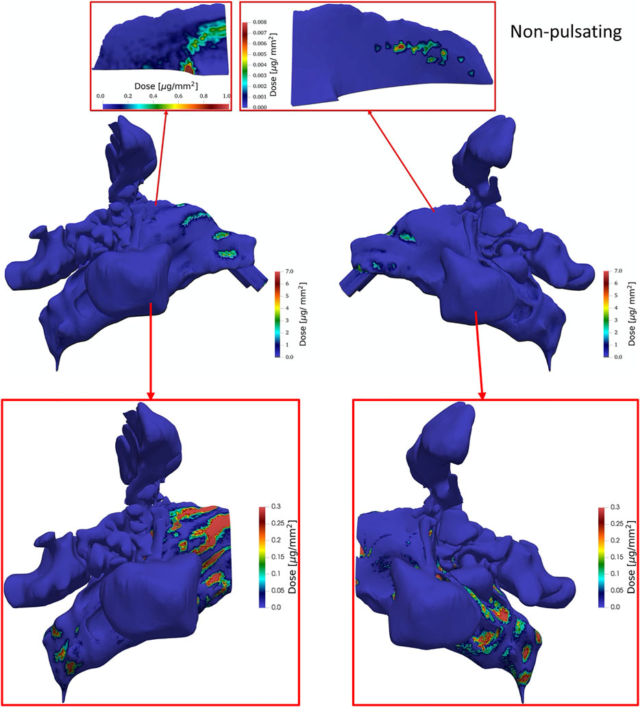
FIGURE 11. The contour plots of tissue-delivered particle dose (of 1 µm particles) presented as mass of particles per surface area tissue at t = 1.98 s (end of inhalation) in the entire nasal airway from right and left views (middle) as well as a reduced section of the nasal airway without the high dose section in the anterior part of the nasal cavity (bottom) and a close-up view of right and left olfactory regions (top) for non-pulsatile aerosol delivery with an aerosol concentration of 75 g/m3 (particle density assumed 1 kg/m3; water), constant flow rate of 4 L/min and a total inhaled dose of 2.5 mg.
Figure 12 is analogous to Figure 11, except that pulsatile aerosol delivery (4 L/min, 45 Hz) is presented. Pulsation of the airflow has almost completely avoided the deposition of particles along the direction of the nosepiece. Therefore, the dose in the regions that reside along the direction of the nosepiece is much lower compared to the condition that non-pulsatile (steady) aerosol delivery is used. In contrast to non-pulsatile aerosol delivery, there are no high dose regions in the upper parts after the nasal valve. However, similar to the non-pulsating aerosol delivery, the regions with highest doses are observed at the vestibule and nasal valve. Analogous to Figure 11 the dose in regions after the nasal valve are separately shown with their corresponding values. Pulsation of the airflow reduces the extreme accumulation of particles in the regions that stand as obstacle perpendicular to the flow direction.
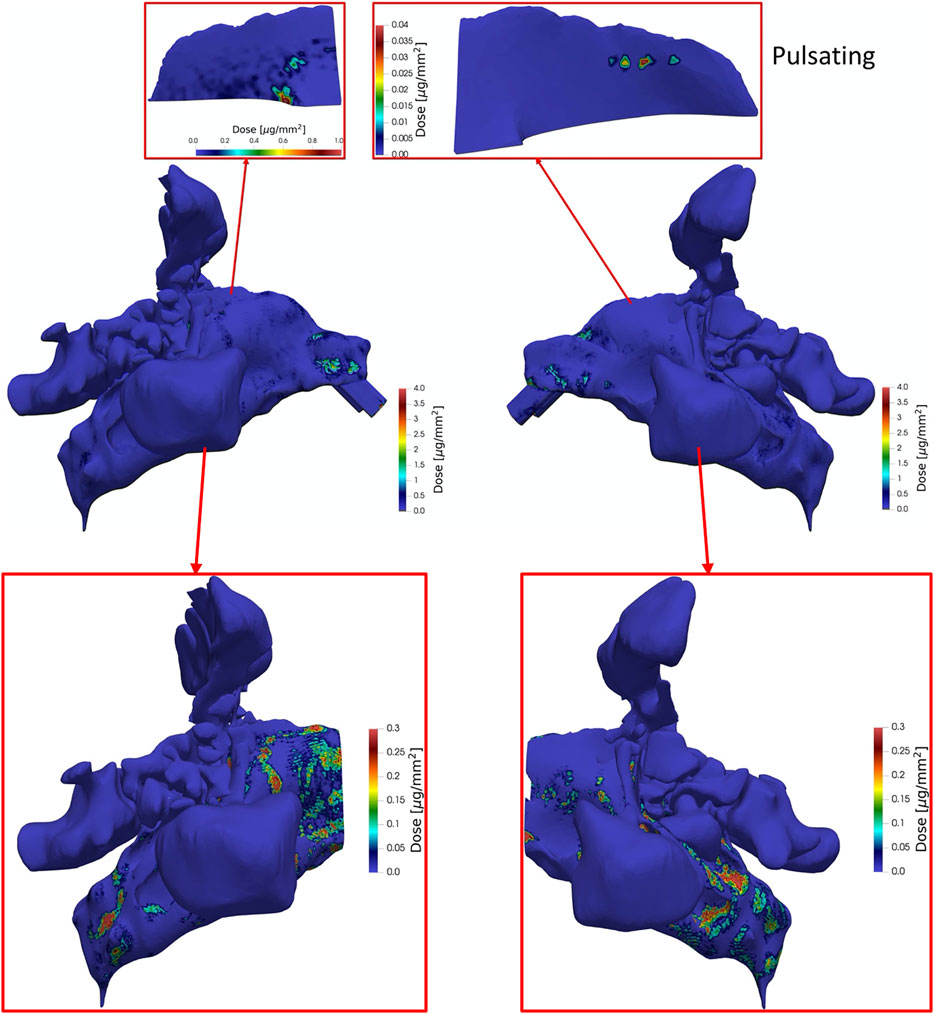
FIGURE 12. Same as Figure 11 except that pulsating aerosol delivery with pulsation flowrate of 4 L/min and frequency of 45 Hz at t = 1.98 s (end of inhalation) was applied.
Analogous to Figure 10, average dose per area of epithelium in the nasal cavity is reduced due to pulsation. Figure 13 shows that there is almost no dose (<0.2 ng/mm2) deposited in the left olfactory region irrespective of pulsation conditions, while ca. 54–602-fold higher doses per area (9—36 ng/mm2) are delivered to the right olfactory region with pulsatile and constant flow conditions respectively. However, pulsatile airflow reduces the dose by a factor of ∼3.95 in the right olfactory region.

FIGURE 13. Comparison of average dose per area in the right and left nasal cavity (left panel) and the olfactory regions (right panel) for non-pulsatile and pulsatile aerosol delivery with average airflow rate of 4 L/min. The dose is presented as mass per area at t = 1.98 s (end of inhalation). The surface areas of the right (left) nasal cavities and olfactory regions are 21,393.1 mm2 (21,249.80 mm2) and 330 mm2 (337 mm2), respectively.
As seen from Figures 11, 12 and analogous to DE (Figure 10), pulsating flow reduces the right-left imbalance of deposited dose (per area) for both the entire cavity and the olfactory epithelium region. This is due to both reduced and enhanced aerosol deposition in the right and left half of the nose (both cavity and olfactory region), respectively. Albeit the DE in the right cavity (50.9 and 34.4%) is 68-fold and 162-fold higher than that in the right olfactory region for non-pulsating and pulsating flow, respectively (Figure 10), the average local dose (mass per area) in the right cavity is 1.05-fold and 2.5-fold higher than that in the right olfactory region for non-pulsating and pulsating conditions, respectively. This is mainly due to the ca. 64-fold lower area of the olfactory region as compared to nasal cavity. On the other hand, the local dose in the olfactory region is ca. 100-fold lower than that in the left cavity independent of pulsation conditions.
In summary, bidirectional inhalation of 1 µm aerosol provides relatively high nasal DE (>34.4%) and about the same average local (surface-specific) drug dose in the olfactory epithelium (ca. 36 ng/mm2) as observed in the nasal cavity for the right half of the nose (inhalation side). This is not the case for the left half of the nose, where the local aerosol dose in the olfactory regions is ca. 100-fold lower than in the nasal cavity. Hence, pulsatile flow did reduce the right-left imbalance in terms of DE, but not to levels where similar right-left local doses could be observed. Owing to the intricate nasal geometry the spatial aerosol deposition was highly non-uniform with very pronounced dose hotspots of up to 1,000 ng/mm2 even in the olfactory epithelium region (Figures 11, 12). Bidirectional aerosol delivery substantially enhanced the total nasal deposition efficiency for 1 µm particles carried by steady inhalation rate of 4 L/min compared to the conventional bilateral aerosol delivery method [50.9 versus ca. 1% (Shi et al., 2007; Shang et al., 2015)]. Similarly, bidirectional aerosol delivery enhanced the olfactory deposition efficiency compared to bilateral aerosol delivery with 1 µm particles [0.48 versus 0.1% (Si et al., 2013)].
The main reason for this extremely large difference between left and right olfactory deposition can be seen in Figures 4, 5. For the non-pulsating flow, streamlines impinge on the top part of the cavity after the nasal valve, and the air passes with relatively high-speed through the right olfactory region. In contrast, due to the oscillating nature of the pulsatile flow, streamlines after the nasal valve are moderated and mixed resulting in lower air speed than that of the non-pulsatile (constant) flow when passing through the right olfactory region. Only for the right nasal cavity, one can observe some streamlines going into the olfactory region, but none are going into the left olfactory region. Since reduced air flow towards the epithelium results in reduced impaction of particles, pulsation reduces particle deposition for all regions where particle deposition is mostly affected by convective transport (impaction) of particles. This is the case for all regions, except the left olfactory epithelium region where convection is virtually absent. Thus, we assume that in this region the oscillatory-flow-induced particle deposition, which has also been reported for non-ventilated paranasal sinuses (Möller et al., 2014), accounts for this finding. This almost complete lack of convective transport into the olfactory region (at least for the left side) can be interpreted as a “protective” mechanism of the olfactory nerve. This nerve is supposed to be sensitive to adsorbed smell-related molecules. Since these molecules reach the olfactory region quite effectively via diffusion (as indicated by large C values in this region, which is indicative of the diffusion of air molecules), the lack of convective transport protects the olfactory region from dust particles, which might deposit onto the olfactory tissue and impair the sensitivity of the olfactory nerve. This hypothesis would have to be substantiated by investigating nasal cavities from other individuals.
Hence, targeting of 1 µm particles to the olfactory tissue with bi-directional flow appears to be difficult. While pulsatile aerosol flow leads to a 3-fold enhanced deposition (DE) in the left olfactory epithelium region, there is a 3.9-fold DE reduction in the right one. The net effect is a more uniform aerosol deposition in the left and right olfactory region, but there is still a ca. 50-fold higher DE in the right olfactory region (inlet side). This suggests that the olfactory region is either not sufficiently conducive to acoustic resonance (which is possibly, since it is completely open on one side of the cavity, rather than fully enclosed with a small opening as required for a Helmholtz resonator) or its resonance frequency is too far away from 45 Hz. We consider the former more likely than the latter.
The effects of different parameters such as morphological differences in various individuals, different inlet flow rates, and particle sizes could play significant role in optimization of particle deposition in olfactory epithelium which should be optimized in future studies.
4 Conclusion
In the present study, a CT-based geometry of the nasal cavity and paranasal sinuses with open mouth (closed soft palate condition) was reconstructed and CFD simulations of bi-directional aerosol delivery w/o flow pulsation were performed. The modeling was validated with experimental data on generic bend geometries and actual measurements of realistic nasal aerosol deposition with normal (bilateral) flow (in casts).
Often computational aerosol deposition studies are only interpreted with respect to deposition efficiency (DE), but for therapeutic intervention the local deposited drug dose (mass per area) is more relevant. In this study, this revealed that, in spite of a relatively low DE (<1%) in the olfactory region, the local drug dose in the olfactory region was on a similar level (ca. 36 ng/mm2) as in the rest of the nasal cavity on the inhalation side owing to the ca. 64-fold smaller area covered by the olfactory region. As a caveat we mention that both in the olfactory and cavity region hot spot doses of up to ca. 1,000 ng/mm2 have been observed. While pulsative flow alleviated some of the right-left imbalance of aerosol deposition, a ca. 54-fold enhanced dose on the inhalation side (right) remained. On the other hand, pulsatile flow reduced the DE in both the nasal cavity and the olfactory region.
From this we conclude that pulsation does not provide a substantial benefit over bidirectional flow without pulsation. Bidirectional aerosol delivery substantially enhances DE both in olfactory region and total nasal airway compared to conventional bilateral aerosol delivery method.
These considerations also suggest two options for relatively efficient drug delivery (ca. 0.5% dose efficiency) to the olfactory region leveraging 1 µm aerosol and bi-directional constant flow conditions (no flow pulsation). (1) The olfactory region of the inhalation side of the nose can be targeted very effectively with a single bidirectional inhalation. (2) For efficient drug delivery to both sides of the olfactory region, two consecutive inhalations should be performed—once through each of the nostrils.
Data Availability Statement
The original contributions presented in the study are included in the article/supplementary files, further inquiries can be directed to the corresponding author.
Author Contributions
AF: Writing—original draft, Writing—reviewing and editing, methodology, software, validation, visualization, analysis. HT: Software, analysis, visualization, reviewing, and editing. IB: Medical Image, Resources, investigation, validation. AM: Reviewing and editing. MR: Conceptualization, Supervision. MM: Reviewing and editing, Supervision. OS: Conceptualization, supervision, reviewing, and editing, analysis.
Conflict of Interest
The authors declare that the research was conducted in the absence of any commercial or financial relationships that could be construed as a potential conflict of interest.
Publisher’s Note
All claims expressed in this article are solely those of the authors and do not necessarily represent those of their affiliated organizations, or those of the publisher, the editors, and the reviewers. Any product that may be evaluated in this article, or claim that may be made by its manufacturer, is not guaranteed or endorsed by the publisher.
Acknowledgments
The authors acknowledge the high-performance computing time at the bwForCluster MLS and WISO Production is acknowledged which is funded by the state of Baden-Württemberg through bwHPC and German Research Foundation (DEG) through grant INST 35/1134-1 FUGG.
References
Ahookhosh, K., Saidi, M., Mohammadpourfard, M., Aminfar, H., Hamishehkar, H., Farnoud, A., et al. (2021). Flow Structure and Particle Deposition Analyses for Optimization of a Pressurized Metered Dose Inhaler (pMDI) in a Model of Tracheobronchial Airway. Eur. J. Pharm. Sci. 164, 105911. doi:10.1016/j.ejps.2021.105911
Alam, S., Khan, Z. I., Mustafa, G., Kumar, M., Islam, F., Bhatnagar, A., et al. (2012). Development and Evaluation of Thymoquinone-Encapsulated Chitosan Nanoparticles for Nose-To-Brain Targeting: a Pharmacoscintigraphic Study. Int. J. Nanomedicine 7, 5705–5718. doi:10.2147/IJN.S35329
Breuer, M., Baytekin, H. T., and Matida, E. A. (2006). Prediction of Aerosol Deposition in Bends Using LES and an Efficient Lagrangian Tracking Method. J. Aerosol Sci. 37 (11), 1407–1428. doi:10.1016/j.jaerosci.2006.01.013
Celik, I. B., Cehreli, Z. N., and Yavuz, I. (2005). Index of Resolution Quality for Large Eddy Simulations. J. Fluids Eng. 127 (5), 949–958. doi:10.1115/1.1990201
Chen, J., Zhang, C., Liu, Q., Shao, X., Feng, C., Shen, Y., et al. (2012). Solanum tuberosum Lectin-Conjugated PLGA Nanoparticles for Nose-To-Brain Delivery: In Vivo and In Vitro Evaluations. J. Drug Target. 20 (2), 174–184. doi:10.3109/1061186X.2011.622396
Chen, J. Z., Kiaee, M., Martin, A. R., and Finlay, W. H. (2020). In Vitro assessment of an Idealized Nose for Nasal spray Testing: Comparison with Regional Deposition in Realistic Nasal Replicas. Int. J. Pharm. 582, 119341. doi:10.1016/j.ijpharm.2020.119341
Cheng, Y. S., Holmes, T. D., Gao, J., Guilmette, R. A., Li, S., Surakitbanharn, Y., et al. (2001). Characterization of Nasal spray Pumps and Deposition Pattern in a Replica of the Human Nasal Airway. J. Aerosol Med. 14 (2), 267–280. doi:10.1089/08942680152484199
Crowe, C. T., Schwarzkopf, J. D., Sommerfeld, M., and Tsuji, Y. (2011). Multiphase Flows with Droplets and Particles. Boca Raton, FL: CRC Press.
Dastan, A., Abouali, O., and Ahmadi, G. (2014). CFD Simulation of Total and Regional Fiber Deposition in Human Nasal Cavities. J. Aerosol Sci. 69, 132–149. doi:10.1016/j.jaerosci.2013.12.008
Djupesland, P. G. (2013). Nasal Drug Delivery Devices: Characteristics and Performance in a Clinical Perspective-A Review. Drug Deliv. Transl. Res. 3 (1), 42–62. doi:10.1007/s13346-012-0108-9
Djupesland, P. G., and Skretting, A. (2012). Nasal Deposition and Clearance in Man: Comparison of a Bidirectional Powder Device and a Traditional Liquid spray Pump. J. Aerosol Med. Pulm. Drug Deliv. 25 (5), 280–289. doi:10.1089/jamp.2011.0924
Djupesland, P. G., Skretting, A., Winderen, M., and Holand, T. (2006). Breath Actuated Device Improves Delivery to Target Sites beyond the Nasal Valve. Laryngoscope 116 (3), 466–472. doi:10.1097/01.MLG.0000199741.08517.99
Edwards, D. A., Hanes, J., Caponetti, G., Hrkach, J., Ben-Jebria, A., Eskew, M. L., et al. (1997). Large Porous Particles for Pulmonary Drug Delivery. Science 276 (5320), 1868–1871. doi:10.1126/science.276.5320.1868
Farnoud, A., Baumann, I., Rashidi, M. M., Schmid, O., and Gutheil, E. (2020a). Simulation of Patient-specific Bi-directional Pulsating Nasal Aerosol Dispersion and Deposition with Clockwise 45° and 90° Nosepieces. Comput. Biol. Med. 123, 103816. doi:10.1016/j.compbiomed.2020.103816
Farnoud, A., Cui, X., Baumann, I., and Gutheil, E. (2017). Numerical Simulation of the Dispersion and Deposition of a Spray Carried by a Pulsating Airflow in a Patient-Specific Human Nasal Cavity. Atomization Sprays. 27, 913-928. doi:10.1615/atomizspr.2017020782
Farnoud, A., Tofighian, H., Baumann, I., and Garcia, G. J. M. (2020b). Large Eddy Simulations of Airflow and Particle Deposition in Pulsating Bi-directional Nasal Drug Delivery. Phys. Fluids. 32, 101905. doi:10.1063/5.0024264
Fazil, M., Md, S., Haque, S., Kumar, M., Baboota, S., Sahni, J. K., et al. (2012). Development and Evaluation of Rivastigmine Loaded Chitosan Nanoparticles for Brain Targeting. Eur. J. Pharm. Sci. 47 (1), 6–15. doi:10.1016/j.ejps.2012.04.013
Ferrante, A., and Elghobashi, S. (2007). On the Accuracy of the Two-Fluid Formulation in Direct Numerical Simulation of Bubble-Laden Turbulent Boundary Layers. Phys. Fluids 19, 045105. doi:10.1063/1.2717722
Frey, W. H., Liu, J., Chen, X., Thorne, R. G., Fawcett, J. R., Ala, T. A., et al. (1997). Delivery of125I-NGF to the Brain via the Olfactory Route. Drug Deliv. 4 (2), 87–92. doi:10.3109/10717549709051878
Ghahramani, E., Abouali, O., Emdad, H., and Ahmadi, G. (2014). Numerical Analysis of Stochastic Dispersion of Micro-particles in Turbulent Flows in a Realistic Model of Human Nasal/upper Airway. J. Aerosol Sci. 67, 188–206. doi:10.1016/j.jaerosci.2013.09.004
Hinds, W. C. (1999). Aerosol Technology : Properties, Behavior, and Measurement of Airborne Particles. New York: Wiley.
Hosseini, S., and Golshahi, L. (2019). An In Vitro Evaluation of Importance of Airway Anatomy in Sub-regional Nasal and Paranasal Drug Delivery with Nebulizers Using Three Different Anatomical Nasal Airway Replicas of 2-, 5- and 50-Year Old Human Subjects. Int. J. Pharm. 563, 426–436. doi:10.1016/j.ijpharm.2019.04.019
Hsu, D.-J., and Chuang, M.-H. (2012). In-vivo Measurements of Micrometer-Sized Particle Deposition in the Nasal Cavities of Taiwanese Adults. Aerosol Sci. Tech. 46 (6), 631–638. doi:10.1080/02786826.2011.652749
Inthavong, K. (2019). A Unifying Correlation for Laminar Particle Deposition in 90-degree Pipe Bends. Powder Tech. 345, 99–110. doi:10.1016/j.powtec.2018.12.095
Inthavong, K., Ge, Q., Se, C. M. K., Yang, W., and Tu, J. Y. (2011). Simulation of Sprayed Particle Deposition in a Human Nasal Cavity Including a Nasal spray Device. J. Aerosol Sci. 42 (2), 100–113. doi:10.1016/j.jaerosci.2010.11.008
Keeler, J. A., Patki, A., Woodard, C. R., and Frank-Ito, D. O. (2016). A Computational Study of Nasal Spray Deposition Pattern in Four Ethnic Groups. J. Aerosol Med. Pulm. Drug Deliv. 29 (2), 153–166. doi:10.1089/jamp.2014.1205
Kelly, J. T., Asgharian, B., Kimbell, J. S., and Wong, B. A. (2004). Particle Deposition in Human Nasal Airway Replicas Manufactured by Different Methods. Part I: Inertial Regime Particles. Aerosol Sci. Tech. 38 (11), 1063–1071. doi:10.1080/027868290883360
Kleven, M., Melaaen, M. C., Reimers, M., Røtnes, J. S., Aurdal, L., and Djupesland, P. G. (2005). Using Computational Fluid Dynamics (CFD) to Improve the Bi-directional Nasal Drug Delivery Concept. Food Bioproducts Process. 83 (2), 107–117. doi:10.1205/fbp.04403
Macpherson, G. B., Nordin, N., and Weller, H. G. (2009). Particle Tracking in Unstructured, Arbitrary Polyhedral Meshes for Use in CFD and Molecular Dynamics. Commun. Numer. Methods Eng. 25 (3), 263–273.
Martínez, J., Piscaglia, F., Montorfano, A., Onorati, A., and Aithal, S. M. (2015). Influence of Spatial Discretization Schemes on Accuracy of Explicit LES: Canonical Problems to Engine-like Geometries. Comput. Fluids 117, 62–78. doi:10.1016/j.compfluid.2015.05.007
Minier, J.-P., Peirano, E., and Chibbaro, S. (2003). Weak First- and Second-Order Numerical Schemes for Stochastic Differential Equations Appearing in Lagrangian Two-phase Flow Modeling. Monte Carlo Methods Appl. 9 (2). doi:10.1515/156939603322663312
Mistry, A., Stolnik, S., and Illum, L. (2009). Nanoparticles for Direct Nose-To-Brain Delivery of Drugs. Int. J. Pharm. 379 (1), 146–157. doi:10.1016/j.ijpharm.2009.06.019
Möller, W., Schuschnig, U., Bartenstein, P., Meyer, G., Häussinger, K., Schmid, O., et al. (2014). Drug Delivery to Paranasal Sinuses Using Pulsating Aerosols. J. Aerosol Med. Pulm. Drug Deliv. 27 (4), 255–263. doi:10.1089/jamp.2013.1071
Moukalled, F., Mangani, L., and Darwish, M. (2016). The Finite Volume Method in Computational Fluid Dynamics: An Advanced Introduction with OpenFOAM® and Matlab. Cham: Springer.
Nicolaou, L., and Zaki, T. A. (2016). Characterization of Aerosol Stokes Number in 90° Bends and Idealized Extrathoracic Airways. J. Aerosol Sci. 102, 105–127. doi:10.1016/j.jaerosci.2016.09.003
Patankar, S. V., and Spalding, D. B. (1972). A Calculation Procedure for Heat, Mass and Momentum Transfer in Three-Dimensional Parabolic Flows. Int. J. Heat Mass. Transf. 15 (10), 1787.
Pope, S. B. (2004). Ten Questions Concerning the Large-Eddy Simulation of Turbulent Flows. New J. Phys. 6, 35. doi:10.1088/1367-2630/6/1/035
Pui, D. Y. H., Romay-Novas, F., and Liu, B. Y. H. (1987). Experimental Study of Particle Deposition in Bends of Circular Cross Section. Aerosol Sci. Tech. 7 (3), 301–315. doi:10.1080/02786828708959166
Schroeter, J. D., Garcia, G. J., and Kimbell, J. S. (2011). Effects of Surface Smoothness on Inertial Particle Deposition in Human Nasal Models. J. Aerosol Sci. 42 (1), 52–63. doi:10.1016/j.jaerosci.2010.11.002
Shang, Y. D., Inthavong, K., and Tu, J. Y. (2015). Detailed Micro-particle Deposition Patterns in the Human Nasal Cavity Influenced by the Breathing Zone. Comput. Fluids 114, 141–150. doi:10.1016/j.compfluid.2015.02.020
Shi, H., Kleinstreuer, C., and Zhang, Z. (2006). Laminar Airflow and Nanoparticle or Vapor Deposition in a Human Nasal Cavity Model. J. Biomech. Eng. 128 (5), 697–706. doi:10.1115/1.2244574
Shi, H., Kleinstreuer, C., and Zhang, Z. (2007). Modeling of Inertial Particle Transport and Deposition in Human Nasal Cavities with wall Roughness. J. Aerosol Sci. 38 (4), 398–419. doi:10.1016/j.jaerosci.2007.02.002
Si, X. A., Xi, J., Kim, J., Zhou, Y., and Zhong, H. (2013). Modeling of Release Position and Ventilation Effects on Olfactory Aerosol Drug Delivery. Respir. Physiol. Neurobiol. 186 (1), 22–32. doi:10.1016/j.resp.2012.12.005
Sweby, P. K. (1984). High Resolution Schemes Using Flux Limiters for Hyperbolic Conservation Laws. SIAM J. Numer. Anal. 21 (5), 995–1011. doi:10.1137/0721062
Syrakos, A., Varchanis, S., Dimakopoulos, Y., Goulas, A., and Tsamopoulos, J. (2017). A Critical Analysis of Some Popular Methods for the Discretisation of the Gradient Operator in Finite Volume Methods. Phys. Fluids 29 (12), 127103. doi:10.1063/1.4997682
Taheri, M. H., Pourmehran, O., Sarafraz, M. M., Ahookhosh, K., Farnoud, A., and Cui, X. (2021). Effect of Swirling Flow and Particle-Release Pattern on Drug Delivery to Human Tracheobronchial Airways. Biomech. Model. Mechanobiol. 20, 2451–2469. doi:10.1007/s10237-021-01518-5
Tian, L., Shang, Y., Dong, J., Inthavong, K., and Tu, J. (2017). Human Nasal Olfactory Deposition of Inhaled Nanoparticles at Low to Moderate Breathing Rate. J. Aerosol Sci. 113, 189–200. doi:10.1016/j.jaerosci.2017.08.006
Tofighian, H., Amani, E., and Saffar-Avval, M. (2019). Parcel-number-density Control Algorithms for the Efficient Simulation of Particle-Laden Two-phase Flows. J. Comput. Phys. 387, 569–588. doi:10.1016/j.jcp.2019.02.052
Wang, S. M., Inthavong, K., Wen, J., Tu, J. Y., and Xue, C. L. (2009). Comparison of Micron- and Nanoparticle Deposition Patterns in a Realistic Human Nasal Cavity. Respir. Physiol. Neurobiol. 166 (3), 142–151. doi:10.1016/j.resp.2009.02.014
Xi, J., Wang, Z., Nevorski, D., White, T., and Zhou, Y. (2017). Nasal and Olfactory Deposition with Normal and Bidirectional Intranasal Delivery Techniques: In Vitro Tests and Numerical Simulations. J. Aerosol Med. Pulm. Drug Deliv. 30 (2), 118–131. doi:10.1089/jamp.2016.1295
Keywords: nose to brain drug delivery, olfactory region, bi-directional aerosol delivery, pulsatile drug delivery, computational fluid dynamics, large eddy simulations
Citation: Farnoud A, Tofighian H, Baumann I, Martin AR, Rashidi MM, Menden MP and Schmid O (2021) Pulsatile Bi-Directional Aerosol Flow Affects Aerosol Delivery to the Intranasal Olfactory Region: A Patient-Specific Computational Study. Front. Pharmacol. 12:746420. doi: 10.3389/fphar.2021.746420
Received: 23 July 2021; Accepted: 05 October 2021;
Published: 23 November 2021.
Edited by:
Ana Fortuna, University of Coimbra, PortugalReviewed by:
Adriana Oliveira Santos, University of Beira Interior, PortugalMatt Wachowiak, The University of Utah, United States
Copyright © 2021 Farnoud, Tofighian, Baumann, Martin, Rashidi, Menden and Schmid. This is an open-access article distributed under the terms of the Creative Commons Attribution License (CC BY). The use, distribution or reproduction in other forums is permitted, provided the original author(s) and the copyright owner(s) are credited and that the original publication in this journal is cited, in accordance with accepted academic practice. No use, distribution or reproduction is permitted which does not comply with these terms.
*Correspondence: Ali Farnoud, YWxpZmFybm9kQGdtYWlsLmNvbQ==, YWxpLmZhcm5vdWRAaGVsbWhvbHR6LW11ZW5jaGVuLmRl
 Ali Farnoud
 Hesam Tofighian
 Ingo Baumann5
 Mohammad M. Rashidi
 Otmar Schmid