 Edward W. Collings1
 Lanchun Lu
 Mike D. Sumption
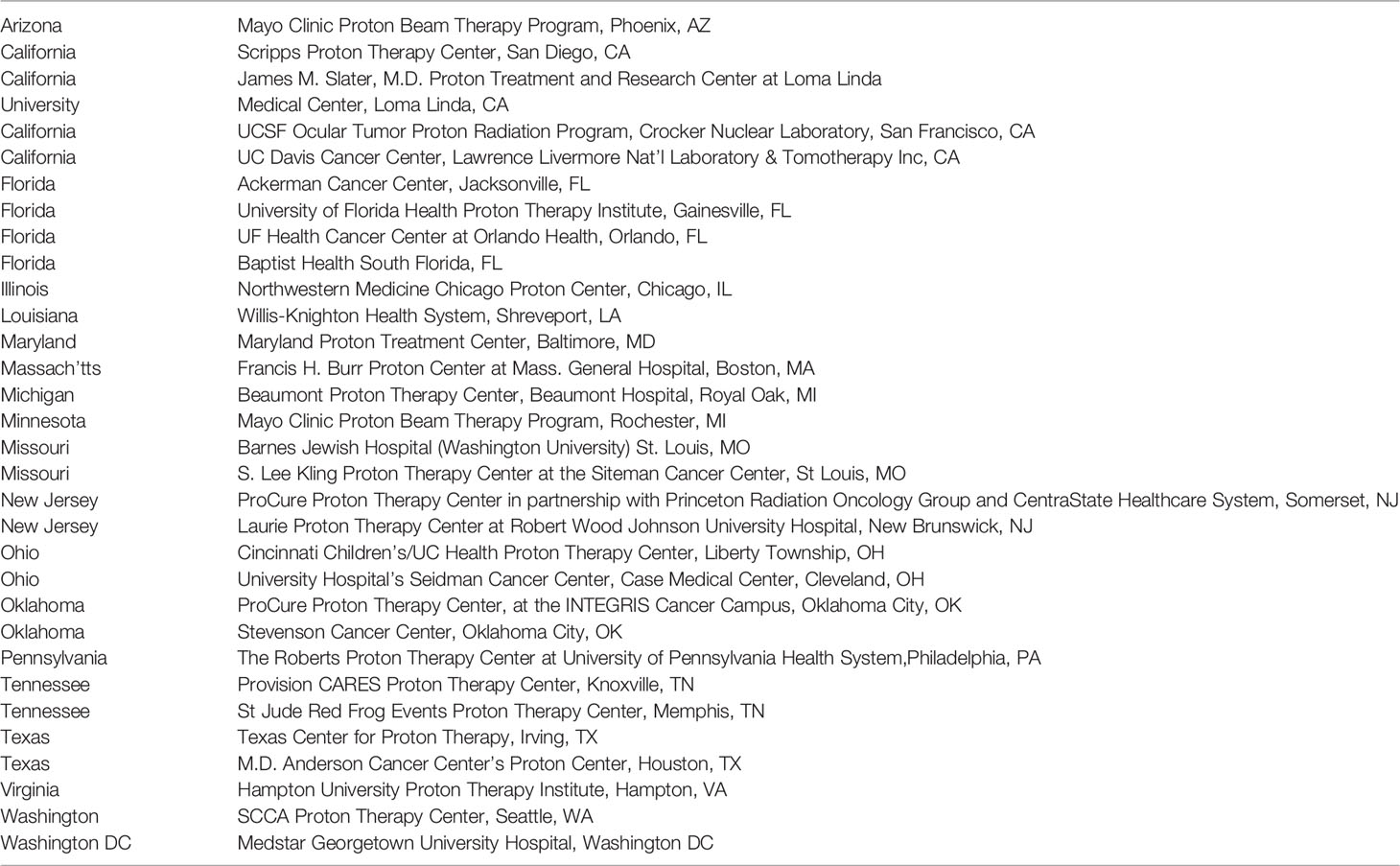

95% of researchers rate our articles as excellent or good
Learn more about the work of our research integrity team to safeguard the quality of each article we publish.
Find out more
REVIEW article
Front. Oncol. , 15 February 2022
Sec. Radiation Oncology
Volume 11 - 2021 | https://doi.org/10.3389/fonc.2021.737837
The paper begins by emphasizing the clinical and commercial importance of proton or other charged particle such as carbon ion therapy, refers to the manufacturers of such systems of which more than 120 are installed or under construction worldwide by April 2021. A general review of charged particle therapy systems refers to six manufacturers and provides in tabular form some details of systems installed in the US, Europe, Asia, and elsewhere. In a description of the principles of particle beam therapy a comparison is made of the properties of photons (x-rays) versus protons and protons versus carbon ions. A brief discussion of accelerators in general is followed by descriptions of cyclotrons (including the isosynchronous cyclotron and the synchrocyclotron) and synchrotrons. An interesting case study describes the evolution of a normal-conducting 220 ton cyclotron into an iron-free synchrocyclotron weighing only 5 tons. The general principles of beam handling and gantry design are described. Subsequent sections describe gantry magnets in detail - normal conducting gantry magnets, superconducting gantry magnets for proton- and carbon therapy. Mention is made of a novel CERN-designed superconducting toroidal gantry for hadron therapy, GaToroid. This device, operating under steady state current and magnetic field, is able to deliver a beam at discrete angles over a range of treatment energies. Also considered are low temperature superconducting (LTS) and high temperature superconducting (HTS) magnet windings, and the choice of REBCO conductors for cryogen-free carbon-ion gantries. Finally, the paper mentions an important “Prospect for Improvement”, viz: the introduction of MRI image guidance. A well-known property of the particle beam as it passes through tissue is its energy dependent absorption that rises to a pronounced peak (the Bragg peak) at the end of its range. In order to take advantage of this effect the exact targeting of the tumor and positioning of the patient should be guided by imaging visualization using X-ray, CT, and hopefully advanced MRI. Unlike MRI-guided photon therapy the direct interaction of the magnetic field with the charged particle beam presents a huge challenge such that MRI image-guided proton/particle therapy has not yet been available in clinical practice. Modeling studies have been undertaken on the general topic of beam-line/magnetic field interaction using, for example, the software GEANT4 (GEometry And Tracking) a platform for simulating the passage of charged particles through matter using a Monte Carlo method.
2014: During year 2014 more than 140 treatment rooms were serving 14,500 patients
2015: In year 2015 only 0.5% of radiation-needy patients were treated with proton therapy.
2019: By year 2019 330 patient treatment rooms are expected to be available, but even then only 1% of radiation-needy patients will be able to receive particle therapy.
2030: By year 2030 it is expected that 1200 to 1800 treatment rooms will be open to patients worldwide. But even 1800 rooms will allow only 5% of radiation-needy patients to receive particle therapy.
2000: In year 2000 the proton therapy market was valued at US$ 1 million
2015: During year 2015 the market reached US$ 800 million (1, 2)
2019: In year 2019 the market is expected to reach more than US$ 1 billion
During 2000-2014 the average annual growth rate was almost 15% p.a.
During 2010-2014 the growth rate underwent acceleration to 22% p.a.
2030: By year 2030 the proton therapy world market is expected to be worth US$ 3.5 to 6.6 billion in response to an annual growth rate of 11% to 16%.
In 2015 there was reported to be 15 manufacturers or developers of ion therapy equipment, and it was predicted that by 2019 the market would be dominated by 5 of those companies. Important manufacturers include: Ion Beam Applications (IBA), Varian, Sumitomo, Hitachi, Toshiba, Siemens, and Mitsubishi, the latter having installed at least 11 proton- or carbon-ion centers in Japan. Of the more than 60 proton therapy facilities worldwide 25 are located in the US. After a slow start the proton therapy market began to accelerate in response to: (i) a growing recognition of the effectiveness of particle therapy, (ii) the recent introduction of lower cost compact systems and single-treatment-room centers. CERN, with its experience in proton accelerator technology (e.g. the LHC) continues to make important contributions to ion therapy. Proton/carbon-ion centers in Japan, Europe-and-Elsewhere, and the U.S. are listed in Tables 1–3, respectively.
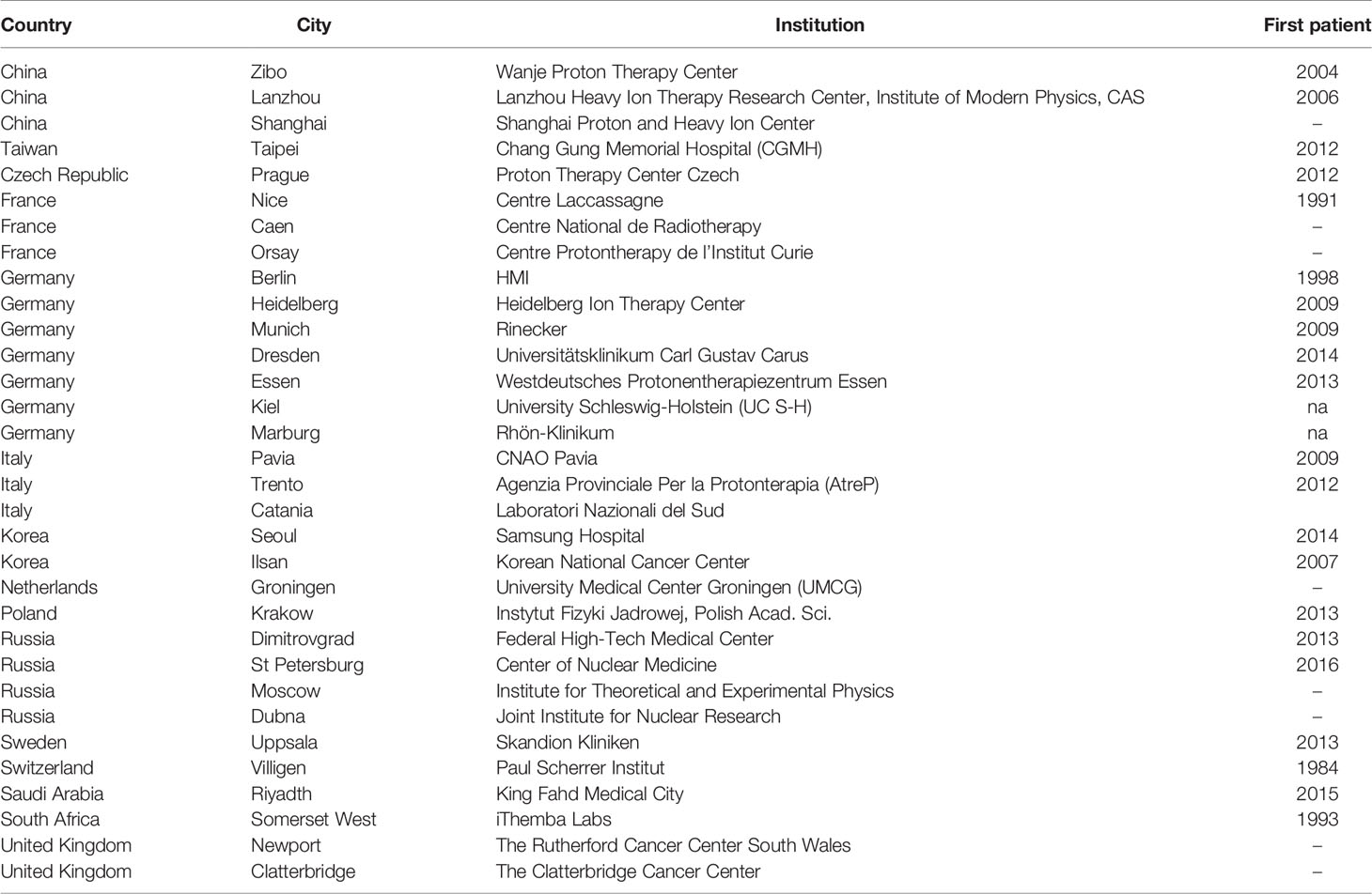
Table 1 Partial listing of particle therapy centers in europe and elsewhere.
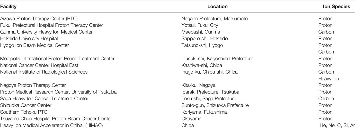
Table 2 Particle therapy centers in Japan.
An increasing interest is also being shown in carbon/heavy-ion therapy, institutions offering which include: The National Institute for Radiological Sciences (Chiba), Hyogo Ion Beam Medical Center (Hyogo), Gunma University Heavy Ion Medical Center (Gunma), Saga Heavy Ion Medical Accelerator in Tosu (Saga), and Shanghai Proton and Heavy Ion Center (SPHIC, Siemens). In 2019 the program “Next Ion Medical Machine Study” (NIMMS) was established to support R&D based on CERN accelerator technology relevant to heavy ion therapy. It is also interesting to note that in a partnership between IBA and Toshiba the latter will become the Japanese distributor of IBA’s Proteus ONE compact single-room proton therapy facility, and IBA will become Toshiba’s carbon-therapy agent outside Japan. Carbon-ion centers worldwide are listed in Table 4.
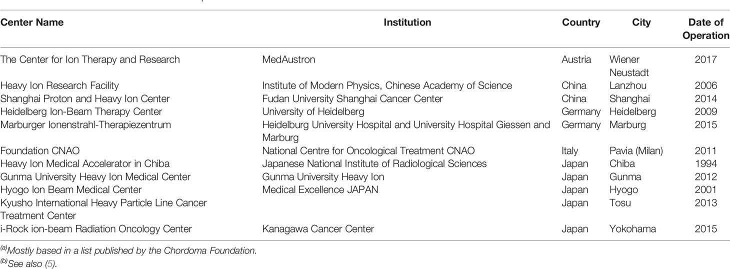
Table 4 Carbon-Ion centers worldwide(a)(b)..
Review articles on proton therapy (6, 7) begin by citing the work of Robert Wilson of the Lawrence Berkeley Laboratory who in a paper published in 1946 (8) was the first to point out the importance of the proton Bragg peak for targeted radiation therapy. As protons pass through tissue at velocity v they continuously lose kinetic energy by inelastic Coulomb scattering against atomic electrons. The rate of energy loss, being proportional to 1/v2, rises sharply as the protons slow down, the end of their range, and form the Bragg peak. Protons also undergo repulsive non-elastic interactions with atomic nuclei and will be deflected from their original path. The product of such interactions may be secondary protons, heavier ions, neutrons, and gamma rays. These non-elastic proton-nucleus interactions, although less frequent than proton-electron ones have a stronger effect (9).
For a detailed description of the history of proton therapy systems reference (7) is recommended. That same article also gives the locations and provides technical details (as of 2010) of 6 commercial proton beam therapy systems (PTS), viz: The IBA Proteus® 235 PTS, Sumitomo PTS, Varian PTS, Still River Systems Monarch 250 (Mevion Medical Systems) PTS, Hitachi PROBEAT PTS, and Mitsubishi PTS. The Hitachi and Mitsubishi systems are based on synchrotron acceleration and the others on cyclotrons. Mitsubishi is particularly active in Japan; a list of their installed proton- and carbon-ion systems is given in Table 5. A complete list of Japanese installations is given in Table 2 and lists of European and US particle therapy installations are given in Tables 1, 3.
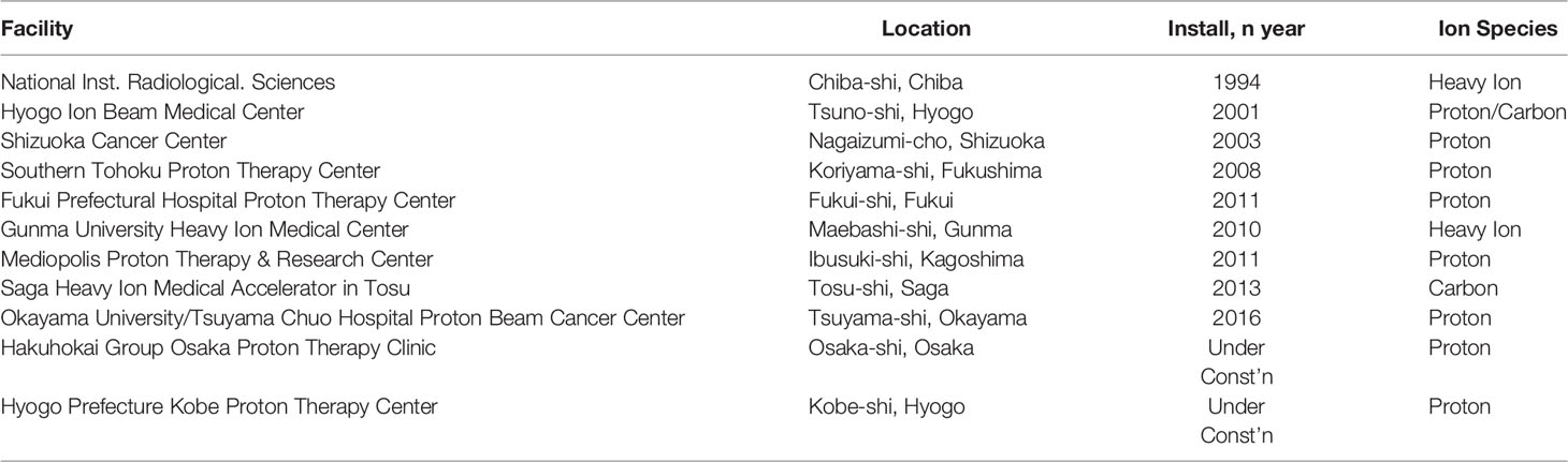
Table 5 Mitsubishi particle therapy systems (10).
Excellent companions to the present document are two recently published reviews. In a paper entitled “Superconducting Magnets for Medical Accelerators” (11) S. Prestemon offers an introduction to hadron therapy and considers the challenges presented by superconducting technology. Cyclotrons and synchrotrons are reviewed, also gantries in general including TULIP (TUrning Linac for Proton Therapy) and ULICE (for Union of Light Ion Centres in Europe) which involves 20 European installations coordinated by CNAO (Pavia, Italy, see Section 4.1). L. Rossi assembled a document entitled “HITRI+ and I-FAST: Next Eu programs for SC heavy ion therapy machine” (12) which outlined the status of ion therapy in Europe and Asia. Considered were HIT (the Heidelberg Ion Beam Therapy Centre, see Section 5.5), and HIMAC (the Heavy Ion Medical Accelerator in Chiba, see Section 5.7.1). Also described was the carbon ion superconducting gantry collaboration involving CNAO (Pavia, Italy, see Section 4.1), MedAustron (Weiner, Austria, see Section 4.1), CERN, and INFN.
In convention radiation (photon) therapy the absorption of x-rays or gamma rays is intensive at the surface and decreases with distance into the subject. Thus in traditional therapy a high intensity of photons must be administered using the isocentric convergence technique to allow multiple beams with the diminished intensity focus at the tumor site. As a result, much of the photon’s energy causes damage to healthy tissue.
In contrast to photons, charged particles are “silver bullets” whose interactions with matter are characterized by the Bragg curve. The energy loss by charged particle through matter is described by this curve which rises to a maximum (the Bragg peak) just before the end of the particle’s track. The peak occurs because the cross section for particle-matter interaction increases just before the particle comes to rest. In particle therapy the beam energy is adjusted either electrically (synchrotron accelerators) or by filters (cyclotron accelerators) to ensure that the Bragg peak occurs at the tumor site. Figures 1, 2 illustrate relative dose versus depth from the body surface for photon- and charged-particle radiation. This indicates that while photon therapy is characterized by relatively high entrance and exit doses, proton therapy has not only a lower entrance dose but a negligible exit dose. It also shows that the position of the Bragg peak can be adjusted to ensure that the tumor receives the intended radiation. This allows patients to receive high radiation doses with low risk of collateral tissue damage.
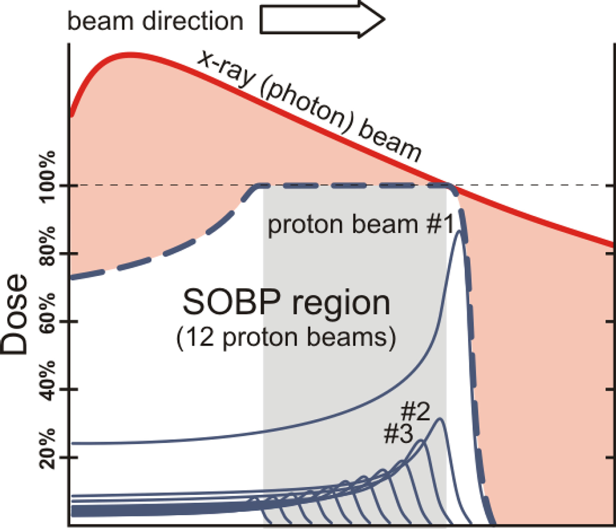
Figure 1 Photons versus protons showing entrance and exit doses and the spread-out Bragg peak (SOBP) – after W.P. Levin et al. (13).
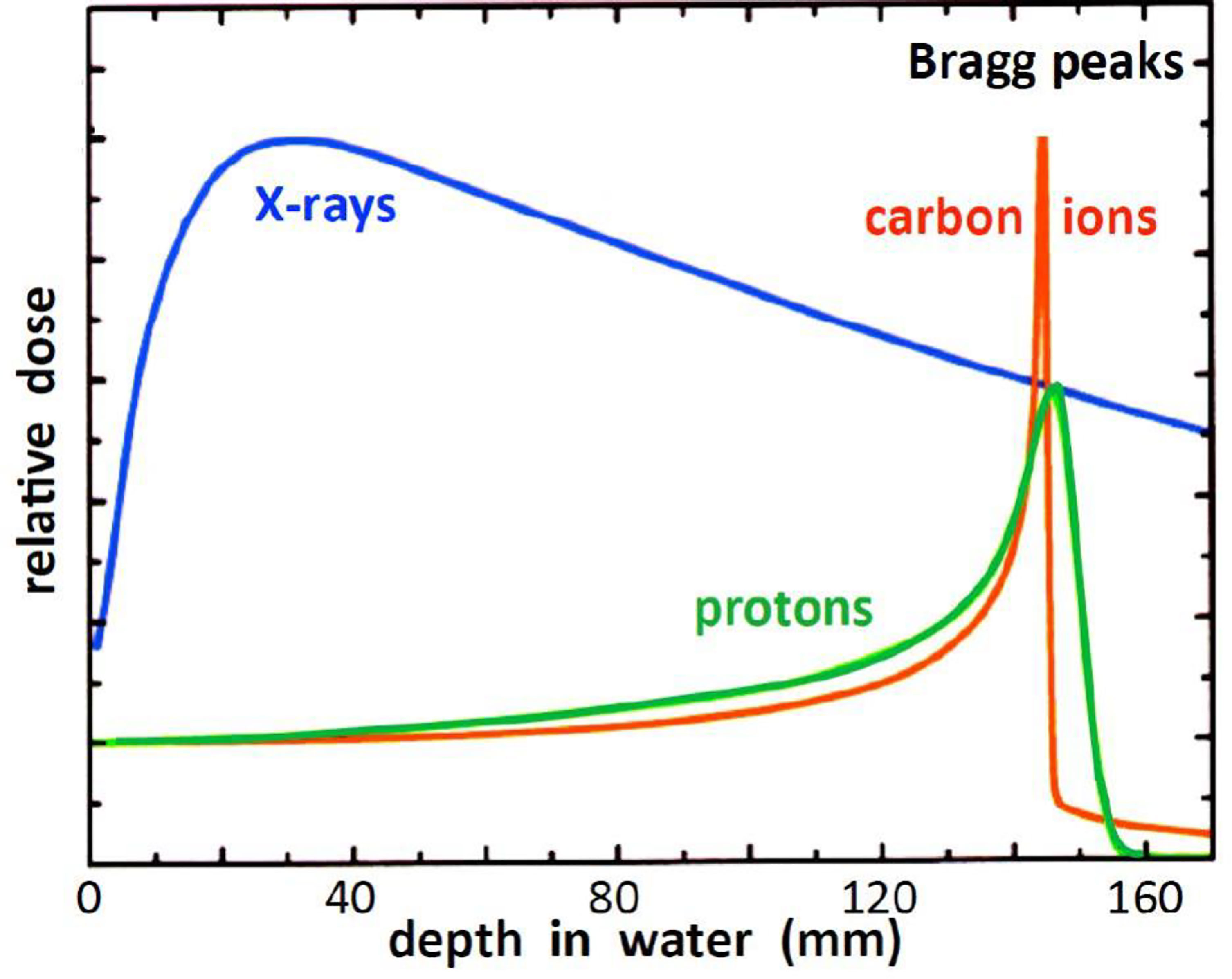
Figure 2 Relative dose versus depth from the body surface for photon- and charged-particle radiation – after (14).
The radiobiological effectiveness (RBE) of photon (traditional, x-ray) therapy is arguably equivalent to that of proton therapy, however as illustrated in Figures 1 and 2, a relatively large proportion of the photon’s energy is deposited in the entrance and exit healthy tissue regions. A distinct advantage of proton beams is that by modulating the energy to create a spread-out Bragg peak (SOBP) a large fraction of the beam energy can be deposited in the tumor site. This advantage is shared by heavy (in particular carbon) ions but in addition, being heavier than protons, they provide a higher RBE, that also increases with depth and rises to a maximum at the end of their range in the tumor region (15, 16).
Photon and proton radiation tend to produce only single-strand DNA breakage. Since cells can repair such breaks damage to both strands is required for successful treatment. Carbon ions are able to produce double-strand breaks that cannot be repaired. In other words the RBE of carbon ions against DNA is up to three times greater than that of x-rays while protons are only slightly more effective. Whereas a full treatment with protons may require 30 sessions just four days may be needed for carbon.
For hadron therapy in general, ions of He, Li, B, N, O, Ne (7), Ar, and Si (17) have also been considered, Section 4.2.
Beams of ionized particles are accelerated and bent by the magnetic fields of cyclotrons, synchrotrons, and dipoles. If the particle velocity, v, is greater than one-third c, the velocity of light, a relativistic correction γ = 1/√[1-(v/c)2] is applied to some of the equations. Thus the velocity (m/s) of an E MeV particle of rest mass m0 can be deduced from E = m0c2(γ-1) in SI units (1 MeV = 1.602x10⁻¹³ J). The bend radius ρ of a beam of particles of momentum p = m0γv and charge q deflected by a magnetic field B is given in SI units by:
The quantity p/q = (m0γv/q) which has the units Tm is known as the “magnetic rigidity”, e.g (5). It represents the reluctance of the ion beam to being deflected by the field B. The energy-dependent rigidities of some proton and carbon beams are listed in Table 6, see also Appendix A. The table demonstrates that heavy ions beams are more difficult to deflect than proton beams and hence require stronger magnetic fields
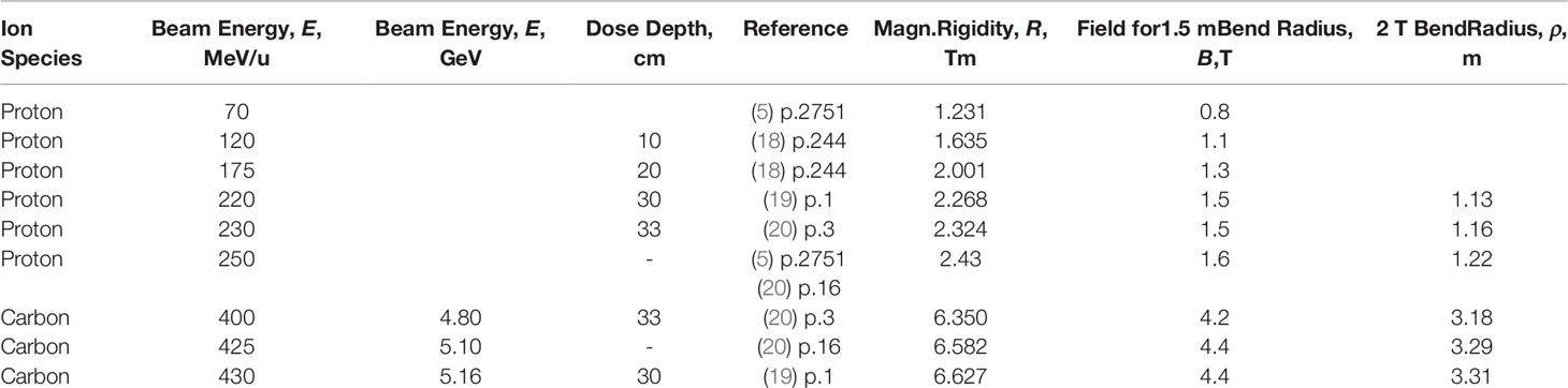
Table 6 Ion energies and dose penetration depths, also calculated magnetic rigidities, fields for 1.5-m-Bend radius, and 2-T-Dipole bend radii.
Hadrons are accelerated in circular paths by cyclotrons or synchrotrons. In a modification of Equation (1) the path radius is proportional to (M/Q)(v/B) in which M represents ionic mass (number of protons and neutrons in the nucleus) and Q represents the ionic charge (number of stripped electrons). Thus as suggested in (7) a hadron synchrotron can accelerate a long list of 0.5-(Q/M) ions, in particular:
hydrogen (accelerated as molecule). Q/M = 0.5
helium, Q/M = 2/4.0 = 0.5
lithium, Q/M = 3/6.9 = 0.43
boron, Q/M = 5/10.8 = 0.46
carbon, Q/M = 6/12.0 = 0.50
nitrogen, Q/M = 7/14.0 = 0.50
oxygen, Q/M = 8/16.0 = 0.50
neon, Q/M = 10/20 = 0.50
argon Q/M = 18/39.9 = 0.45
silicon Q/M = 14/28.1 = 0.50
Protons are the commonly used ions, accelerated to 220-230 MeV/u they can travel 30-33 cm into the body. Fewer systems use carbon ions which have about the same range at 400 MeV/u.
For injection into a synchrotron that accelerates them to final beam energy (21) particles are typically pre-accelerated by a radiofrequency quadrupole (RFQ) cavity accelerator (7, 22) followed by a drift-tube linear accelerator (DTL) (7, 23). The numerous processes that exist for injection into cyclotrons have been discussed in detail by Mandrillon (24). Some commercial accelerators are listed in Table 7.

Table 7 Accelerators for proton and/or carbon-Ion therapy – some commercial vendors.
CERN, with its experience in proton accelerator technology (e.g. the LHC) continues to make important contributions to ion therapy. Some 20 years ago CERN initiated the program “Proton Ion Medical Machine Study” (PIMMS) whose purpose was to produce a synchrotron tailored to treat tumors with protons and carbon ions. The design evolved into a proton and carbon ion machine built for CNAO (Italy’s National Center for Oncological Hadron Therapy, Pavia Italy, Tables 1 and 4). Subsequently MedAustron (Weiner, Austria, Tables 1 and 4) with technical support from CERN based its clinic on the CNAO design. In 2019 the program “Next Ion Medical Machine Study” (NIMMS, led by M. Vretenar) was established to support R&D based on CERN accelerator technology relevant to heavy ion therapy.
Therapy synchrotrons yield beams of relatively low intensity and of variable energy. Protons are injected into a ring of dipoles at 2-7 MeV and accelerated up to 70-250 MeV as the dipole field is ramped. Synchrotrons can be up to 20 m in diameter. The first hospital-installed proton therapy system was based on a Fermilab synchrotron to be further developed by Optivus Technology. Other vendors such as Hitachi, Mitsubishi, Toshiba, and Siemens followed suit, Table 7. But as Jongen has pointed out (7) about 75% of today’s proton therapy systems are based on cyclotron technology
The cyclotron consist of an RF system situated between the poles of a normal-wound or superconducting electromagnet. Considered below are the classical “traditional” cyclotron, the isochronous cyclotron, and the synchrocyclotron.
This cyclotron incorporates a fixed-field electromagnet. The RF system consists of a pair of hollow D-shaped drift cavities excited by an oscillator of fixed frequency, f, given by 2πf = (q/m)B where q and m are the charge and mass of an assumed non-relativistic particle and B is the field strength. Early on a Sumitomo-ProNova collaboration produced a 230 MeV conventional normal-conducting cyclotron. In 1989 Blosser et al. (25) reported on the development at Michigan State University (MSU) of a 100 MeV superconducting cyclotron for installation at Detroit’s Harper Hospital. The cyclotron and beam delivery system are gantry mounted and will rotate through a 360° arc about the patient.
In this cyclotron the RF frequency is fixed but B varies with radius. Furthermore an azimuthal variation in B provides a strong focussing effect and constrains the particles in their spiral paths. The isochronous cyclotron also called the azimuthal varying field (AVF) cyclotron, is used in many of today’s systems: (i) IBA offered a resistive magnet Proteus®235 system which in 2010 was operating in 9 locations (7); (ii) ProNova produced a 230 MeV superconducting isochronous cyclotron which was about ½ the diameter and ¼ the weight of its resistive one mentioned above; (iii) Varian/ACCEL’s ProBeam system incorporates a 250 MeV isochronous cyclotron, the interesting feature of which is its use of four drift cavities instead of the usual two.
In the synchrocyclotron the RF frequency, fR, is decreased continuously in synchronism with the increasing velocity, v, of the particle within the relativistic regime. Thus fR = (q/mγ)B, where γ = 1/√[1-(v/c)2]. The synchrocyclotron may deploy only one D whose potential oscillates with respect to ground. The circulating particles accelerate as they drift into and out of the D. The IBA Proteus®235 system, a successor to their ProteusOne®, incorporates their model S2C2 superconducting (NbTi) synchrocyclotron and operates at a fixed 230 MeV (26). In 1989 Blosser et al. (27) reported on the design of a 250 MeV superconducting gantry-mounted synchrocyclotron system for proton therapy.
A Sumitomo-ProNova Solutions collaboration produced a normal-conducting 230 MeV cyclotron 4.4 m in diameter weighing 220 tons. The smaller ProNova SC360 system used a superconducting 230 MeV isochronous cyclotron 2.8 m in diameter weighing 50 tons. The Massachusetts Institute of Technology (MIT) in collaboration with ProNova has been working on the design and construction of an iron-free variable energy (70-230 MeV) synchrocyclotron also 2.8 m in diameter but weighing only 5 tons (28). Several advantages accrue from the use of this accelerator: (i) its variable-energy capability removes the need for graphite energy degradation, (ii) its low weight would make it very attractive for gantry mounting, (iii) gantry mounting eliminates the need for beam-directing magnets. Taken together these advantages lead to an attractive proton beam therapy system.
Before it enters the treatment area or gantry the ion beam requires energy adjustment. Therapy cyclotrons generate a fixed-energy beam of typically 230 MeV, the needed energy variation between 60 and 230 MeV being achieved by passing the beam through an “energy degrader, an absorber of variable thickness such as two opposite-facing wedges of graphite. These are followed by a magnetic analyzer consisting of a combination of dipole magnets and collimators (20). The “Energy Selection System” of Ion Beam Applications S.A. (IBA) allows tuning from 60-230 MeV in less than 1 second. Although the beam loss by degradation can be as much as a factor of one hundred or more typical cyclotrons deliver sufficient beam intensity to make up for this. With regard to synchrotron sources, rapid energy variation can be achieved by extracting the ion beam at different times in the acceleration cycle (20). The synchrotron can deliver proton beams in more than 90 energy steps between 73 MeV and 222 MeV corresponding to penetration depths in water of 4 to 31 cm (29).
In the present context a gantry is a massive structure that rigidly holds in place the guidance magnets of ion beam therapy. A typical magnet arrangement is shown in Figure 3. The figure also indicates the so-called “isocenter” or axis about which the gantry rotates thereby enabling the ion beam to enter the tumor in all directions. The term “gantry” may refer to the mechanical structure, the magnet string (5), or the entire system as illustrated in Figure 4.
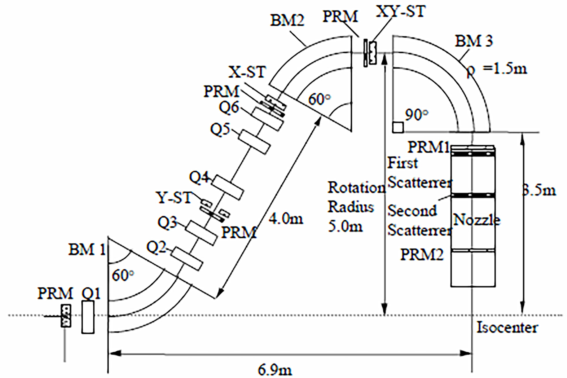
Figure 3 Pavlovic (30) layout of magnets in an ion therapy gantry – after (5). In this example two bending dipoles (BM 1 and BM 2) offset the beam 5 m from the isocenter and dipole BM 3 bends the beam back towards the isocenter and the patient platform. In other systems BM 1 and BM 2 would have other but equal bend angles [e.g. 45° (19)], and still others may employ only two bending magnets (e.g. BM 1 with 45°or 60° and BM 3 with 135°or150°) to achieve the same result (31, 32).
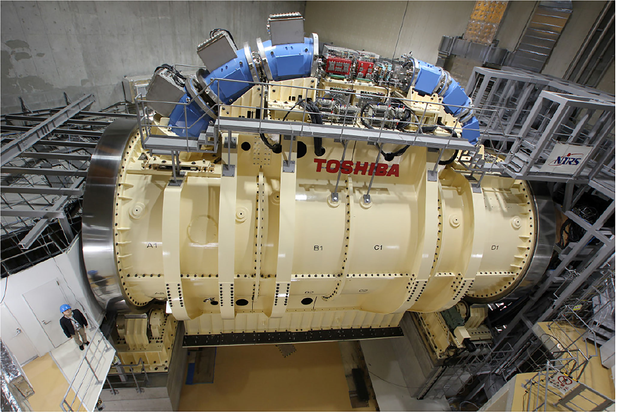
Figure 4 Toshiba’s gantry with superconducting technology capable of 360° rotation about the isocenter – after (33).
Figure 3 illustrates a Pavlovic-type (30) arrangement of magnets and devices in an ion therapy gantry. The beam is bent by three dipole magnets BM 1, BM 2, and BM 3, and kept in focus by six quadrupole magnets Q1 to Q6. The beam enters the gantry through a monitor PRM that monitors and records the center of the beam and its size. Three other PRMs are associated with steering magnets for beam trajectory correction and two more, PRM1 and PRM2, are located in the nozzle. Several nozzle arrangements have been used to passively or actively spread the mm-size beam over a treatment area that may be as large as 30 cm2 (5, 34). Described in detail by (31) are: (i) uniform scanning nozzles, (ii) pencil scanning nozzles, (iii) single scattering nozzles, and (iv) double scattering nozzles. The latter version is represented in Figure 3.
During a typical treatment session a proton beam energy may need to be varied from 70 to 250 MeV. This produces a change in rigidity of from 1.231 to 2.431 Tm requiring the field of a 1-m-radius dipole to track the beam energy and hence increase from 1.23 to 2.43 T. In the absence of field-change a typical normal dipole will accept a beam momentum change, dp/p, of less than 1% ( (35), p.2). Tumors are typically scanned in layers 5 mm deep enabled by a momentum sweep of 1% ( (35), p.4), the layer-scan taking of order 100 ms. A dp/p of 1% corresponds to a beam energy change dE/E = 2dp/p = 2%. Thus to control a 100 MeV beam (proton magnetic rigidity 1.483 Tm) a 1-m-radius dipole would require a field change of 15 mT. On this basis the average sweep rate of the scan is 150 mT/s (20 times faster than LHC). Taking another approach, a dE/E of 2% implies 50 scanning steps covering the energy range from 70 to 250 MeV and a 1-m-radius dipole field range of 1.23 to 2.43 T. At 100 ms/step this leads to an average sweep rate of 240 mT/s. From another standpoint, at 5 mm per layer a proton-beam-depth range of 10-35 cm would require 50 scanning steps, leading to the same result.
Sweep rates of hundreds of mT/s cause stability and energy-loss problems for superconducting magnets. So when considering a gantry upgrade from normal-conducting to superconducting magnets these high ramp rates created a demand for achromatic bending dipoles with wide momentum acceptances, such dp/p = 5-10%, 25%, and 40-50% [(35), p.3]. The use of such magnets, which enable the entire energy range to be covered in just a few steps, eases the ramp-rate requirement.
As outlined in (20) the use of normal-conducting iron-core dipole magnets with their maximum bore field, B, of about 1.8 T governs the size of most commercial gantries. At a typical 250 MeV proton beam rigidity, R = 2.43 Tm the 1.8 T field calls for a bending radius ρ = R/B = 1.35 m. The addition of 3.5 m for distance from the nozzle entrance to the isocenter leads to a gantry rotation radius of about 5 m (Figure 3). Thus proton gantries are about 10-12 m in diameter, 7-10 m long (Figure 3 also (18)) and weight about 100-200 tons (20). Further details are provided in Appendix B.
Much larger than the above proton gantries is the famous carbon-ion gantry of the Heidelberg Ion Beam Therapy Centre (HIT). The maximum treatment beam energy of 425 MeV/u yields a beam rigidity of 6.58 Tm (Table 6) which calls for a 1.8 T dipole radius of ρ = R/B = 3.65 m. The supporting gantry is ≈ 12 m in diameter, ≈ 21 m long, and the overall system (including 135 tonnes of magnets) weighs ≈ 650 tonnes (36). These statistics signaled the beginning and end of normal-conducting carbon-ion gantries and ushered in the need for superconducting magnets (36). In conclusion we note that HIT should not be confused with HITRI+ which stands for “Heavy Ion Therapy Research Initiative” a design study to assess the relative merits of CT and CCT magnets (Sections 5.7.2 and 5.7.4) for synchrotrons (Section 4.2) and CT/CCT and toroids (Section 5.7.6) for gantries.
It is easy to argue that proton gantries are adequately served by normal-conducting magnets. Nevertheless superconductivity has enabled several improvements to gantry and magnet design. Alonso and Antaya (18) considered the size advantage accompanying the substitution of 2 T normal-conducting dipoles with superconducting ones with 4 T or higher fields. The smaller bend radius and smaller size were estimated to reduce the gantry diameter by about 3 m. Alonso et al. have also described a novel gantry concept being developed at the time by ProNova Solutions based on achromatic (9% momentum acceptance) combined-function magnets. In that arrangement a 60° bend was followed by a set of magnets (possibly a pair) contributing to a final 150° bend. The total mass of the magnets was estimated to be less than 5 tons. The “direct replacing” of normal-conducting magnets with superconducting ones should not only lower the weight but also the cost of the gantry. With these advantages in mind Bontoiu and Sanchez-Segovia (37) went on to model a lattice of 36 combined-function superconducting magnets. Inspired by LHC technology the combined-function magnet consists of one layer of quadrupole coils on top of one layer of cos-θ dipole coils. Combined-function magnets possess much larger momentum acceptances than do individual dipoles and quadrupoles. In this case a fixed-field beam energy variation of 50 MeV could be accommodated, enabling an energy range of 100 to 250 MeV to be covered in only three steps. The superconducting gantry design study of Wan et al. (38) was motivated not only by size, weight, and cost considerations but also the need for large energy acceptance. Their design achieved an energy acceptance of ± 21% enabling beams of 150- 30 MeV to be bent without field ramping. Wan et al’s compact fixed-field-alternating-gradient (FFAG) gantry, or magnet string, consisted of three groups of seven achromatic 3.2 T superconducting magnets, each group creating a 90° bend (38).
It was shown in 1970 that an overlaid pair of solenoidal coils tilted in opposite directions could generate a dipolar field normal to the solenoidal axis (39). Exploited in recent years by the superconducting magnet group at the Lawrence Berkeley National Laboratory (LBNL) this tilted-double-helix magnet is now referred to as canted cosine theta, CCT. By suitably modifying the winding scheme quadrupoles and higher order multipoles can also be generated (18). Not only that, but a combined-function magnet can be produced by winding a CCT dipole on top of a CCT quadrupole (40). In pursuing CCT technology the LBNL group went on to introduce a new magnet concept – the alternating-gradient canted cosine theta (AGCCT) magnet (35, 40). In this magnet the inner quadrupole winding consists of multiple sections with the current reversed between sections, e.g. 5 sections for a winding designated FDFDF. LBNL’s design can be characterized as fixed-field alternating-gradient since its large momentum acceptance (~ 25%) enables a large energy range to be transmitted without changing the field. The advantages claimed for gantries incorporating the new magnet design are: (i) an order of magnitude reduction in weight, (ii) possible size reduction, e.g. diameter 5 m and length 8.3 m, and (iii) rapid scanning (35). Gantry layouts described by the LBNL group are: (i) three groups of seven achromatic 3.2 T superconducting magnets (with sextupole and octupole components in the middle five of each group), with each group creating a 90° bend (38), (ii) two 75° AGCCT bending magnet groups to offset the beam 2.5 m “above” the exocenter followed by one 90° AGCCT group (35), (iii) one normal-conducting 45 dipole to deflect the beam “upwards” followed by a single 135° bend to guide the beam back to the exocenter (40). As with other superconducting gantry systems the magnets are intended to be conduction cooled.
Several practice CCT-based coils were wound at LBNL using parallel stacks (6x1 and 8x1) of insulated square (1.6 mm x 1.6 mm) NbTi wire. During the above studies the LBNL group conducted a detailed evaluation of the advantages and disadvantages of Nb3Sn, MgB2, and HTS wires and selected NbTi for a number of reasons [(35) Table 8, see also (41)]. It is interesting to note that the Toshiba Corporation has been considering HTS magnets with the aim of reducing gantry size and has designed and fabricated a model magnet (42).
Table 8 MEVION S250 compact proton therapy systems.
The MEVION S250 system is unconventional in that the gantry carries no beam-transport magnets. Instead the proton beam emanates directly from a gantry-mounted 250 MeV superconducting synchrocyclotron whose magnet, wound with Nb3Sn wire, and cryocooled to 4 K, delivers a central field of 9 T. Weighing only 22 tons Mevion’s SCS is much lighter than comparable machines, e.g. IBA’s 50 ton 230 MeV superconducting synchrocyclotron (see Figure 5). At least 7 S250 systems are presently operational and the S250i with pencil beam scanning is also available, Table 8.
Figure 5 The MEVION S250 gantry-mounted proton synchrocyclotron – after Jongen (7).
Freed from the need for an iron core, superconducting magnets can be much stronger in field and lighter than their normal-conducting counterparts and hence are suitable as hadron-therapy gantry magnets. Whereas a 230 MeV proton beam can achieve a dose depth of 33 cm, carbon ions need to be accelerated to 400 MeV/u (4.8 GeV). Accordingly the magnetic rigidities (M = ρB) of these beams are 2.32 and 6.35 Tm, respectively. The dipole field needed to achieve a 1.5 m 230 MeV proton-beam bend radius is 1.5 T whereas the 400 MeV/u carbon-ion beam requires 4.2 T (Table 6), achievable only in a superconducting magnet. Such magnets can provide very small carbon-beam bend radii; given that ρ = 6.35/B radii of less than 1 m are possible.
The advantage of carbon ions is that, being heavier than protons, they provide a higher RBE. After their pioneering work with proton beams in 1954 LBNL moved on to helium ions in 1957, and neon ions in 1975, but ended all radiotherapy programs in 1992 (15). In 1994 carbon ion radiotherapy (CIRT) was picked up by Japan’s National Institute of Radiological Sciences (NIRS) using the Heavy Ion Medical Accelerator in Chiba (HIMAC). Other centers were soon to follow; five in Japan and others in Austria, China, Germany and Italy ( (7, 15) and Table 4). In spite of its innovative pioneering work the US does not house a single CIRT center, although initial planning has been announced for the establishment of such centers in California and Colorado [(43, 44) see also (45)].
In 2012 Iwata et al. and others from the Toshiba Corporation reported on the design of a rotating gantry system with superconducting magnets for carbon ion therapy (46). Then in 2013 Toshiba received an order from NIRS for such a system, the world’s first (33). The cylindrical gantry is depicted in Figure 4. In addition to a pair of scanning magnets, three pairs of steering magnets and beam profile monitoring magnets it consisted of 10 superconducting combined-function bending magnets. One of the design goals was to achieve a compact superconducting gantry, much smaller than HIT’s room-temperature one and comparable in size (length 13 m, radius 5.5 m) to existing proton gantries. The 10 bending magnets, BM1-10, of the Toshiba/NIRS 430 MeV/u magnet system were arranged in 3 groups – BM1-3, BM4-6 and BM7-10, Table 9.
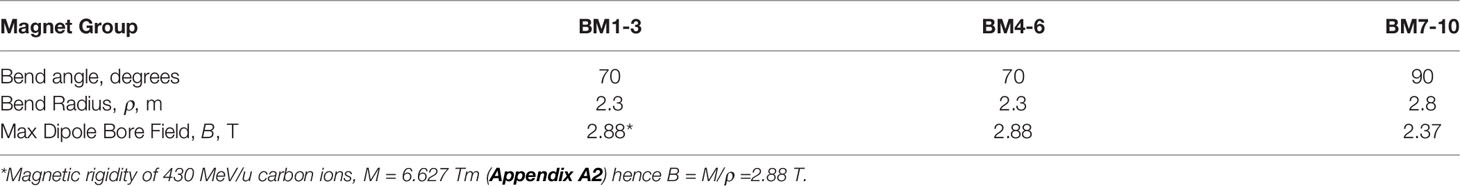
Table 9 Some properties of the toshiba/NIRS superconducting dipoles (46).
The superconducting combined-function coils have a layered structure: the innermost 8 layers being cos(2θ) quadrupoles and the outer 26 layers being cosθ dipoles. The small momentum acceptance of the system necessitated the use of low AC-loss NbTi wire – 10 μm filament diameter with CuNi barriers (47). The magnets were conduction cooled with 1.5W/4.2K Gifford-McMahon cryocoolers. Three sets were mounted on each of BM1-6 and four sets on each of BM7-10 for a total of 34 cryocoolers (47). An even more compact gantry was described by Iwata et al. (48). Consisting of only three identical 90° combined-function magnets it was only 5.1 m in length and 2.5 m in radius. Designed for 430 MeV/u carbon ions and hence a beam rigidity of 6.627 Tm each magnet has a bending radius ρ = 1.32 m and a maximum bore field B = 5.02 T. As described and depicted in (48) the combined-function magnet consisted of a 20-layer of cosθ dipole winding on top of a 6-layer cos(2θ) quadrupole winding.
In 2013 Toshiba began the development HTS magnets one of its aims being to further reduce the size of heavy-ion-therapy gantries (47). Based on Toshiba’s above low-temperature-superconducting gantry an HTS gantry was designed and model magnet designed, built, and tested. Selected for the windings was a REBCO HTS tape 4 mm wide and 0.1 mm thick. Wound with 820 m of tape, the magnet consisted of 24 saddle-shaped REBCO coils stacked in four layers and attached to an iron yoke (47). Conduction cooled to about 4 K by a GM cryocooler the magnet generated a bore field of 1.2 T.
As mentioned in Section 5.5 at the Heidelburg Ion-Beam Therapy Center (HIT) the 135 tonnes of normal-conducting magnets are supported by a 21 m long, 6 m radius, gantry weighing an additional 515 tonnes. The resulting demand for a smaller lighter gantry called for introduction of superconducting magnets. Numerous such systems furnished with conventionally wound cosθ and cos(2θ) dipoles and quadrupoles have been designed and/or constructed, e.g. (33, 46–48).. To still further reduce size and weight the CCT winding was introduced. Numerous reports describe the implementation of CCT winding within the context of proton therapy [e.g. (35, 40)] but the concept should be applicable to both proton and carbon systems.
Robin et al. described a superconducting magnet string for a compact carbon-ion therapy gantry (49). Their gantry 9.97 m long and 3.12 m radius carries two 45° bending dipoles, numerous quadrupoles, and a 90° large aperture final bending magnet. In a paper that focused attention on the 5 T 90° final bending magnet the authors pointed out that the CCT concept could be applied to dipoles, quadrupoles, and bent magnets (“toroids”). Winding schemes to produce the correct combination of dipolar and multipolar fields were developed. The magnet layout of Kim et al. (19) is identical to that of Robin et al. (49). This work also focused attention on the large aperture 90° final bending magnet recognizing that the field to bend 430 MeV/u carbon-ion beam (R = 6.627 Tm) to a radius of 1.269 m is 5.22 T. Sextupole components in the fringe field region of the dipole were removed by adjusting the coil winding in the main body of the dipole.
IFAST (Innovative Fostering of Accelerator Science and Technology, a CERN project) was the subject of a meeting convened by L. Rossi (INFL, Milano) that set out to prepare a proposal dealing with Work Package WP-8 (innovative superconducting magnets (L. Rossi)) and WP-4 (magnet design) (50). The objective of WP-4 included engineering design for the HITRI accelerator magnets (see Section 5.5) and the HITRI gantry magnet.
Bottura, Felcini, et al. (CERN) described the magnetic design of a superconducting gantry in the form of a torus configured for proton or hadron therapy. For the windings of this “GaToroid” both LTS (NbTI) and HTS (REBCO) options were considered. The device eliminates the need for rotating structures and operating at constant current and magnetic field is able to deliver a beam at discrete angles over a wide range of energies, e.g. 70 MeV to 250 MeV.
The designers of ion-beam therapy systems are continually striving for improved beam optics, smaller size, and lower cost. Regarding optics, pencil-beam scanning was early introduced by the vendors. Introduction of the alternating gradient CCT magnet with its large momentum acceptance (~ 25%) enabled large energy ranges to be transmitted at fixed field, thus reducing the need for low-AC-loss magnet windings. Therapy systems consisting of large accelerators, beam lines and gantries are large and expensive. Superconductors went a long way towards reducing their size. Another important step was taken by MEVION which, by mounting a compact 17 ton synchrocyclotron on the gantry frame, eliminated the need for a string of quadrupoles and bending dipoles. Although the MEVION could be fitted with the desired pencil-beam scanning system, the fixed 250 MeV of the synchrocyclotron called for graphite energy degraders to vary the bean energy. A potential improvement would be to introduce the MIT-ProNova-designed 5 ton ironless variable-energy (70-230 MeV) synchrocyclotron.
Sections 5.5 through 5.7 have outlined the evolution of magnet systems and gantries from proton to carbon-ion, from normal-conducting to superconducting, from standard cosθ and cos(2θ) windings, to tilted double-helix (CCT) windings. We see proton magnet system weights decreasing from an estimated 20~40 tons to less than 5 tons. Gantry layouts have been simplified and magnets have been improved, for example: (i) Bontoiu’s proton gantry (37) consisted of a string of 36 combined-function superconducting magnets, (ii) Toshiba’s carbon-ion gantry consisted of 10 combined-function superconducting magnets arranged in 3 groups for bends of 70° (3 magnets), 70° (3 magnets), and 90° (4 magnets) (18, 33, 46) (47), (iii) Another Toshiba carbon-ion gantry consisted of just 3 superconducting combined function 90° bend magnets (48), (iv) substitution of the standard cosθ and cos(2θ) windings by tilted double-helix (CCT) windings, for which several advantages have been claimed viz: (a) an order of magnitude reduction in weight, (b) possible gantry size reduction, e.g. diameter 5 m and length 8.3 m, and (c) rapid scanning (35).
Wan et al. (35) (LBNL) have reviewed the suitability of the well-known low temperature (LTS) and high temperature (HTS) superconductors for gantry magnet windings and conclude that for their proton gantry application NbTi was the conductor of choice. For the windings of their CCT combined-function magnets Wan et al. selected “SSC-inner” NbTi strand 0.8 mm in diameter, filament diameter 6 μm. For one of the magnets the 8 conductors in the two dipole layers will be powered in series and the 26 conductors in the two quadruple layers will be separately powered in series. The suitability of NbTi has also been claimed by others, for example: (i) the 10 magnets of a Toshiba gantry (46) are wound with 0.9 mm diameter NbTi wire, (ii) the 3 combined-function magnets of another Toshiba gantry (48) are wound with 0.92 mm NbTi wire twisted to 6 + 1 for a final cable diameter including insulation of 3.0 mm; the coil currents were 710 A (quadrupole) and 920 A (dipole), (iii) another LBNL magnet (40) was wound with series-connected parallel stacks (6x1 and 8x1) of 1.6 mm square insulated insulated NbTi wires.
With a magnetic rigidity of 6.627 Tm a 430 MeV carbon-ion beam can be bent to a radius of 1 m by a dipole with a bore field of 6.6 T (although the field-at-winding will be higher than this to an extent that depends on magnet design). Wan et al’s (35) review of some of the key properties of the wire-formable LTS and HTS superconductors reminds us that with 4.2 K upper critical fields (Bc2) of 10.5-11 T (NbTi), 19-27 T (Nb3Sn), 9-10 T (MgB2), 70-75 T (Bi2Sr2CaCu2O8+x, i.e. “Bi:2212”), and 92-95 T (YBa2Cu3O7-x, i.e. “REBCO”) they all apparently qualify from a 4.2 K critical field standpoint. Down-selection then involves consideration of other materials properties, magnet fabrication problems, and cryogenic issues. After winding (W) with Nb3Sn wire the magnet needs to be reacted (R) for ~160 hours at temperatures up to 650°C and Bi:2212 coils require ~125 hours at 888°C. MgB2 requires a relatively mild heat treatment (60 min/675°C) and either W&R or R&W coils can be produced. From a manufacturing standpoint MgB2 is more attractive than Nb3Sn and Bi:2212 but its critical field does not leave enough margin to enable conduction cooled operation at the above field strengths. NbTi and REBCO wires in the as-received condition are suitable for coil winding; this is a great advantage. The selection in favor of REBCO, dictated by cryogenic issues, is discussed in the following sections.
The accelerator magnets of high energy physics are wound with high-current-carrying Rutherford cable to maintain a high ampere-turn ratio while minimizing the magnet inductance. Different considerations govern the choice of magnet design and conductor size in superconducting particle beam gantries. Inductance is not an issue but magnet current has to be relatively small to minimize current-lead heat leak into the cryostat. Since the magnet heat load scales with ramp rate a large momentum acceptance (especially if it allows fixed-field operation) is beneficial for thermal design (40). Because the gantry needs to rotate, magnet cooling by liquid helium is not feasible. Instead all superconducting gantry systems are cryogen-free, conduction cooled by way of high conductivity links to cryocooler cold heads. Numerous cold heads may be connected in parallel to various parts of the magnet system (35). The final 90° dipole of a joint IBA/CEA Saclay study was cooled by 10 Sumitomo cryocoolers (18). Mounted on the Toshiba heavy-ion gantry referred to above (47) are 3 groups of 10 bending magnets, BM1-3, BM4-6 and BM7-10. They are conduction cooled with 1.5W/4.2K Gifford-McMahon cryocoolers – three sets on each of BM1-6 and four sets on each of BM7-10 for a total of 34 cryocoolers (47). At a Sumitomo (SHI) model RDK-4150 (1.5W/4.2 K) cold head weight of 18.5 kg (40.8 lb) 34 cryocoolers would contribute about ¾ ton to the weight of the gantry. A lighter gantry could be enabled by circulating gaseous or supercritical helium through the magnets from an off-gantry-mounted cooling and pumping system (51–54) or by implementing a cryogenic oscillating heat pipe system (55).
In 2016 Iwata et al. and others from the Toshiba Corporation reported on the design of a compact gantry for 430 MeV/u carbon ions (48). Each of the three 90° dipoles was to have a bend radius of 1.32 m and hence a dipole field strength of 5.02 T. The results of the design study did not include cryogenics and provided no indication of the feasibility of maintaining a field of 5 T under cryogen-free conditions. On the other hand the Toshiba group did report on the design (46, 47), test results (47), and delivery to NIRS of a heavy ion rotating gantry. As reported above (section 5.7.2, Table 9) the three sets of NbTi-wound bending magnets had maximum fields of 2.88 T, 2.88 T, and 2.37 T. It is doubtful if fields much higher than this can be achieved in commercial conduction-cooled systems. Attempts to build NbTi-wound conduction-cooled magnets for magnetic resonance imaging (MRI) have not succeeded, while recent research and development of conduction-cooled 3 T MRI systems has focused on MgB2. But for ion-beam therapy, to avoid the difficulties associated with reaction-heat-treatment and to gain the advantages of its high Tc, Bc2, and engineering critical current density, JE, and cryogenic stability, REBCO is arguably the conductor of choice.
The 4.2 K, 5 T the JE of “standard” SuperPower REBCO tape at 4.5 x 10³ A/mm2 (B//) (56) is 4 times greater than that of NbTi. An even higher JE (5.4 x 10⁴ A/mm2) is becoming obtainable as a result of: (i) increasing the Zr doping content from 7.5% to 25% (x3), (ii) increasing the film thickness (x2), (iii) reducing the tape thickness from 100 μm to 50 μm (x2). As a result the 4.2 K, 5 T JE of REBCO tape is more than 40 times that of NbTi. One reason for the rejection of REBCO was that tape geometry was not regarded as suitable for magnet winding. This is no longer a problem. REBCO is now available in wire form - thin tapes spirally wrapped along a wire core 0.51-0.8 mm in diameter.
To perform an efficient treatment accurate image guidance techniques that can distinguish a tumor from healthy tissue are required. Imaging is associated with target accuracy, of targeting, dosimetry, treatment outcome assessment, and prognosis. Images are used in radiation therapy during the following processes: (1) offline treatment planning – tumors and other anatomical structures are identified and the treatment is simulated on a treatment planning computer. During this process CT, MRI and even PET-CT or other type of images are commonly used; (2) imaging is applied to set up the patient in the treatment room and to convert the virtual treatment (a treatment plan) into the real treatment; (3) images are used to assess the treatment outcome: effectiveness, toxicities, and prognosis, etc. While Processes 1 and 3 are usually carried out offline, Process 2 is often performed with the imaging device attached to the treatment machine inside the treatment room to align the patient in the treatment position or during the treatment to monitor the targeting of tumors and organs-at-risk. Process 2 is complex and needs to conform to the gantry and the beam delivery system. The currently available image-guided particle therapy systems are mainly based on 2D orthogonal X-ray imaging, in-room 3D computed tomography (CT) or on-board cone-beam CT (CBCT) imaging. However, 3D or 4D CT and MRI images are commonly used off-line for treatment planning (57). Imaging technologies such as the proton Computed Tomography (or pCT) (58, 59) or MR-guided proton therapy have been proposed but are not yet available for clinical use (60). While X-ray based imaging has difficulty resolving soft-tissue the converse is true for MRI-guided particle therapy. MRI guidance in photon (radiation) therapy MRgRT, which entered clinical practice not long ago, gradually became popular during the past decade (61). Currently there are several commercial available MRgRT manufacturers in the market: ViewRay (62), Elekta (63), and Varian Medical Systems/IMRIS (64).
In order to take advantage of the peak effect (discussed in Section 2.1) the exact depth of the tumor (the target) must figure into the treatment. An error in the target depth of a few mm that may result in only a few percent change in the photon dose may lead to a 100% change in the proton dose (67). This emphasizes the need for direct visualization of the tumor position. Such “image guidance” using MRI has been proposed and modeled by numerous researchers (see section 7.3). The principle of MRI guided proton therapy is illustrated in Figure 6.
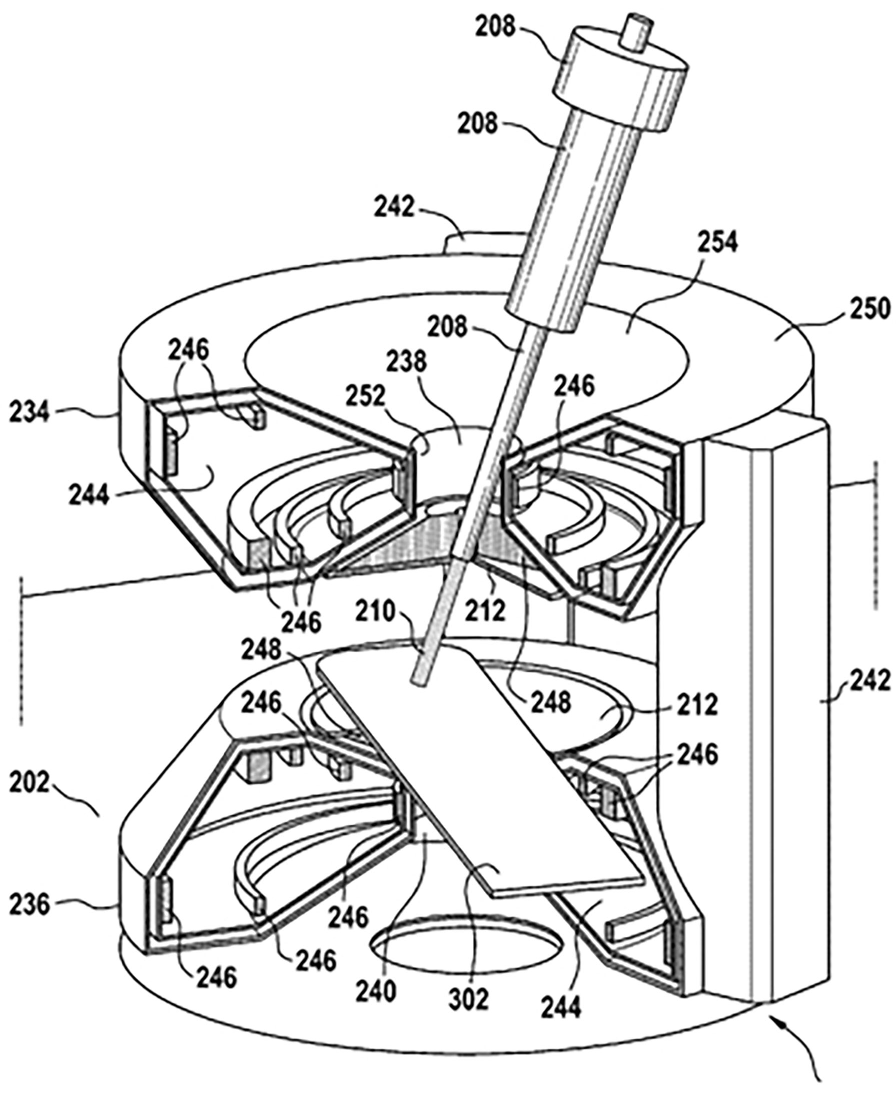
Figure 6 Possible configuration of a hybrid MRI proton system, taken from patent application US 10 , 173 , 077 B2 (45). Date of Patent: Jan. 8, 2019 (67).
Photon irradiation requires a well-defined beam aimed in the right direction. In proton therapy it is also necessary to predict ensure that the beam will terminate at the tumor side. The additional margin needed for range uncertainty detracts from the benefit of proton therapy. Image guidance is introduced to overcome this uncertainty (67). In a combined MRI-proton system it is necessary to consider mutual electromagnetic interaction between the proton beam and the MRI field. For example Monte Carlo computer simulations and measurements have revealed that a 190 MeV proton beam would be deflected by about 1 cm upon entering a 1 T field. Such effects would influence treatment planning and dose delivery. External magnetic fields that could influence MR image quality come from sources such as: (i) the proton generating cyclotron, (ii) the gantry beam line and steering magnets; the fringe field of such magnets, which can be up to 100 µT, could detrimentally affect the MR image quality. To further investigate such effects Hoffmann and his team (65, 66), in association with OncoRay, attached an open 0.22 T MRI scanner to a fixed horizontally mounted proton research beam line, Figure 7.
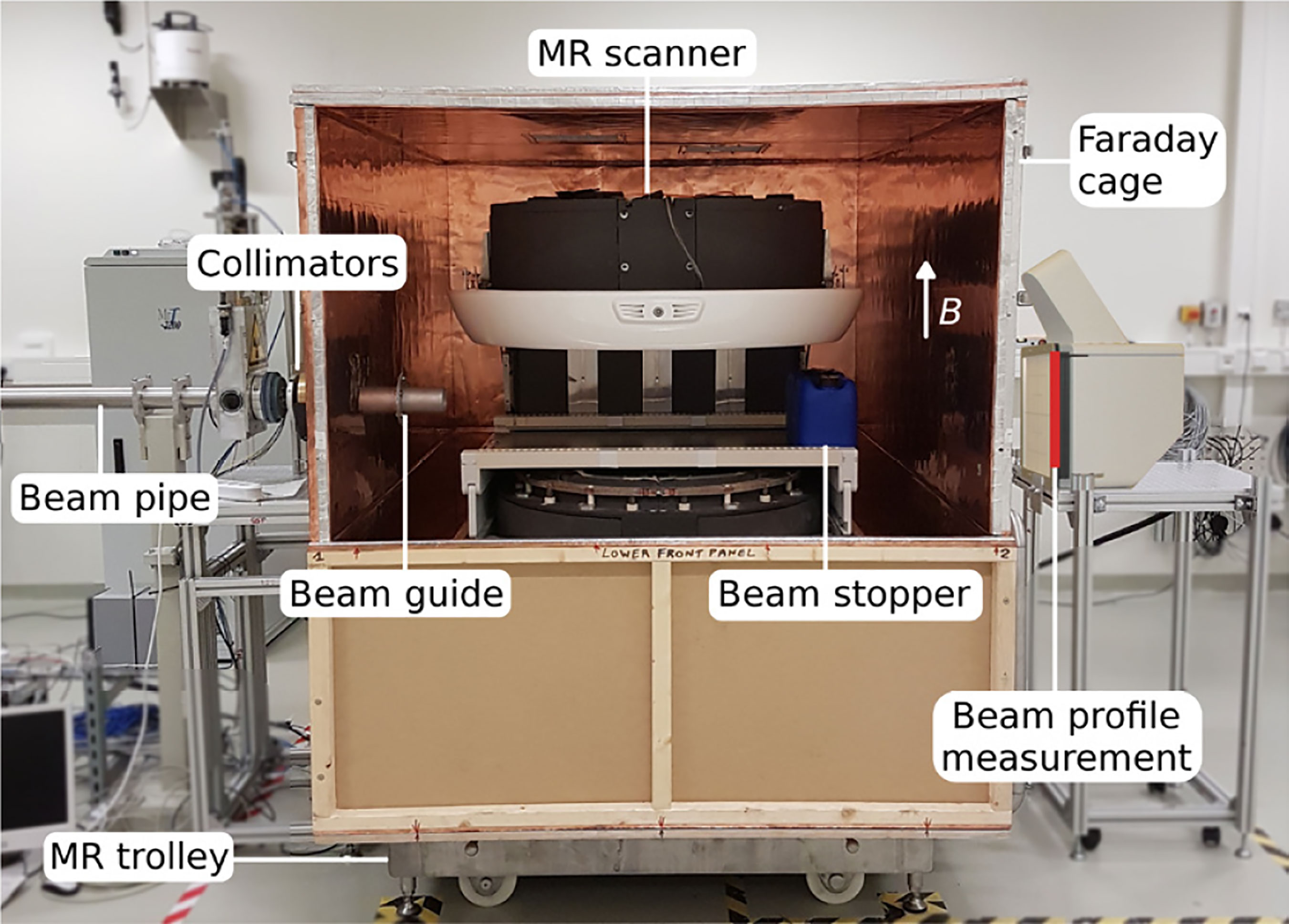
Figure 7 The prototype MR-integrated proton therapy system at the fixed horizontal beam line in the experimental room of the Dresden proton therapy system – after (65, 66).
In a useful experimental study Inaniwa et al. (68) investigated the effects of magnetic fields (0.3 and 0.6 T) applied transversely (BT) and longitudinally (BL) a proton beam adjusted to deposit energies of 1.1 and 3.3 keV/µm into normal and cancer cells. Effectiveness was gauged by the index R10 ≡ DWO/DW which is the ratio of the dose that would result in a survival fraction of 10% in the absence (DWO) and presence (DW) of the magnetic field.
For cancer cells exposed to 1.1 keV (3.3 keV) proton beams R10 increased to 1.10 (1.11) and 1.11 (1.12) in longitudinal magnetic fields (BL) of 0.3 T (0.6 T).
For normal cells R10 increased to 1.13 (1.17) and 1.17 (1.30) in these longitudinal magnetic fields.
For both normal and cancer cells R10 showed no significant change in the transversely applied fields
Inaniwa et al. pointed out that the longitudinal field enhancement effect should be taken into account in the design of an MRI-proton system (68).
No commercial scale versions of the research system described in Figure 7 can be made available for experimentation. However numerous modeling studies have been undertaken on the general topic of beam-line/magnetic-field interactions (see Table 10, Bibliography). Oborn et al. (69) have modeled the path of a proton beam through the 3D field of a 1 T split bore MRI magnet. Used for the modeling was the software GEANT4 (GEometry ANd Tracking), a platform for simulating the passage of charged particles through matter using a Monte Carlo method. Significant rotation of the beam was observed in the longitudinal orientation while a more complex path was seen in the transverse field. It was concluded that pencil beam scanning was favored for either longitudinal or transverse field orientations.
Table 10 Bibliography on MRI-Guided Ion-Beam Therapy.
MRI guidance should be introduced in order take advantage of proton over photon therapy. In so doing the influence of external magnetic fields emanating from the imaging and beam guidance systems on image quality needs to be investigated. In so doing it would be useful to produce an engineering design for a full-scale proton-beam/MRI system (e.g. Figure 6) using GEANT-Monte-Carlo method modeling. In addition (or alternatively) a small-scale experimental prototype MRI-integrated proton therapy system (e.g. Figure 7) could be constructed and used for investigating beam-line/magnetic-field interactions. Given that longitudinal field dose enhancement and other such effects exist, experiments using such a system could be designed to investigate the underlying mechanisms.
To build an effective image-guided or MR-guided proton or particle therapy system, a comprehensive and sophisticated design of accelerator, beam-line, gantry, magnets, and the imaging components needs to be carefully calculated so that all sub-systems could be integrated into a unit that operates efficiently and meets the clinical requirements while reducing cost to a minimum.
The paper begins by emphasizing the clinical and commercial importance of proton and carbon ion (in general, hadron) therapy and refers to the manufacturers of such systems of which more than 120 are installed or are under construction worldwide. A general review of charged particle therapy systems refers to six manufacturers and provides in tabular form some details of systems installed in the US, Europe, Asia, and elsewhere. The principles of particle beam therapy are described in terms of the Bragg peak and the spread-out Bragg peak (SOBP) and a comparison is made of the therapeutic properties of photons (x-rays) versus proton-beams and the latter versus carbon-ions beams. An introduction to particle-beam acceleration is followed by descriptions of normal-conducting and superconducting (SC) cyclotrons (including the isosynchronous cyclotron and the synchrocyclotron) and of synchrotrons. An interesting case study describes the evolution of a normal-conducting 220 ton cyclotron into an iron-free SC synchrocyclotron weighing only 5 tons.
The principles of gantry design and the components of the magnet string are outlined. Particle-beam guidance is described in terms of the beam’s magnetic rigidity and the relationship of bend radius, ρ, to bending-dipole field strength, B. The development of the needed SOBP requires a range of particle-beam energies, typically proton energies of 70-240 MeV. The associated rapid field-sweep would be difficult for SC dipoles unless dipole design allows for broad momentum acceptance. This statement introduces a detailed discussion of gantry magnets for both proton therapy and carbon-ion therapy.
First to be described is the use of normal-conducting iron-core gantry magnets whose 1.8 T bore field calls for bend radii of 1.35 m (250 MeV protons) and 3.65 m (425 MeV/u carbon). Thus although proton gantries are adequately served by such magnets their use in a one-of-a-kind carbon gantry has led to an unacceptably large structure. Both proton and carbon gantries benefit from the use of SC magnets. The “direct replacing” of normal-conducting magnets with SC ones is expected to lower the weight and cost of the gantry.
Several winding arrangements are described. Conventional windings are the familiar cosθ dipolar and cos2θ quadrupolar windings of high energy particle physics. In the present context they have given rise to the combined-function winding in which a cos2θ quadrupole coil is wound on top of a cosθ dipole coil. Such magnets possess much larger momentum acceptances than do individual dipoles and quadrupoles and enable beams of a wide range of energies to be controlled by only a few field steps. The use of conventionally wound SC magnets in both proton and hadron therapy is reviewed. Then an alternative winding, the tilted double helix now referred to as the canted cosine theta (CCT) winding, is introduced A combined-function version of it is produced by winding a cosθ dipole on top of a cos2θ quadrupole. Next to be described is a new magnet concept – the alternating-gradient CCT (AGCCT) – in which the inner quadrupole consists of multiple sections with the current reversed between sections. This design can be characterized as fixed-field alternating-gradient since its large momentum acceptance enables a large energy range to be transmitted without changing the field. Finally, mention is made of a novel CERN-designed superconducting toroidal gantry for hadron therapy, GaToroid. This device, operating under steady state current and magnetic field, is able to deliver a beam at discrete angles over a range of treatment energies.
Cooling of SC rotating gantry magnets is an important engineering task. Cooling by liquid helium is not feasible. Instead some form of liquid-cryogen-free or conduction cooling is required. Some systems make use of locally mounted Gifford-McMahon cryocoolers (typically 1.5W/4.2K each), other suggested cooling modes involve the circulation of gaseous or supercritical helium or the use of a cryogenic oscillating heat pipes.
The choice of superconductor for gantry-magnet winding is discussed in detail. Numerous proton magnets have been wound with NbTi wires – individual 0.8-0.9 mm diameter wires, a (6 + 1)-wire twisted cable, parallel stacks of 1.6 mm square insulated wires. A high-temperature-superconducting (HTS) magnet (bore field 1.2 T), conventionally wound with REBCO tape (4 mm x 0.1 mm), has been designed built and tested. In general the bore fields, even of SC magnets, have been relatively low, often less than 3 T. But for future carbon-ion systems, especially when gantry size and hence dipole bend radius is to be minimized, bore fields of order 6 T will be needed. To satisfy this requirement in a cryogen-free magnet superconductors with critical temperatures and critical fields higher than those of NbTi will be needed. A review of the properties of several low-temperature- and high temperature superconductors indicates that REBCO is the material of choice – not in the form of a difficult-to-wind tape but as a wire (or cable) made from narrow tapes spirally wrapped along a thin wire core.
Finally, an important “Prospect for Improvement” would be the introduction into the system of MRI image guidance. In order to take advantage of the Bragg peak effect the exact targeting of the tumor and positioning of the patient must figure into the treatment. The charged-particle beam has to be guided by image visualization using X-ray, CT, and hopefully MRI. An error in the target depth of a few mm that may result in only a few percent change in photon dose may lead to a 100% change in the proton dose (67). Unlike MRI-guided photon therapy the direct interaction of the magnetic field with the charged particle beam presents a huge challenge such that MRI image-guided proton/particle therapy has not yet been available in clinical practice. Modeling studies have been undertaken on the general topic of beam-line/magnetic field interaction using, for example, the software GEANT4 (GEometry And Tracking) a platform for simulating the passage of charged particles through matter using a Monte Carlo method. The paper concludes by noting that a comprehensive design of accelerators, gantries, magnets and imaging systems for particle beam therapy would be the best way to produce the most efficient and cost effective particle-beam therapy system.
EC wrote the first draft of the manuscript. LL and NG wrote sections of the manuscript. All authors contributed to manuscript revision, read, and approved the submitted version.
This work was supported by the National Institute of Biomedical Imaging and Bioengineering, under grant R01EB018363.
The authors declare that the research was conducted in the absence of any commercial or financial relationships that could be construed as a potential conflict of interest.
All claims expressed in this article are solely those of the authors and do not necessarily represent those of their affiliated organizations, or those of the publisher, the editors and the reviewers. Any product that may be evaluated in this article, or claim that may be made by its manufacturer, is not guaranteed or endorsed by the publisher.
1. Goethals P-E, Zimmermann R. Proton Therapy World Market Report – Edition 2015. Louvain-la-Neuve, Belgium: MEDraysintell (2015).
2. Goethals P-E, Zimmermann R eds. Proton Therapy World Market Report & Directory – Edition 2015. Louvain-la-Neuve, Belgium: MEDraysintell (2016).
3. Available at:protonbob.com/about-proton-therapy/.
4. Available at: www.proton-therapy-canters.com.
5. Norimine T, Umezawa M, Hiramoto K. A Design of a Rotating Gantry With Easy Steering for Proton Therapy. In: Proc. European Particle Accelerator Conference (EPAC 2002). Paris, France: JACOW, (2002). p. 2751–3.
6. Goitein M, Lomax AJ, Pedroni ES. Treating Cancer With Protons. Phys Today (2002) 55:45. doi: 10.1063/1.1522215
7. Jongen Y. Review on Cyclotrons for Cancer Therapy. In: Proc. CYCLOTRONS. Lanzhou, China: JACOW. (2010). p. 398–403.
8. Wilson RR. The Radiological Use of Fast Protons. Radiology (1946-47) 47:487–491. doi: 10.1148/47.5.487
9. Newhauser W, Zhang R. The Physics of Proton Therapy. Phys Med Bio (2016) 60:R155–209. doi: 10.1088/0031-9155/60/8/R155
10. Available at: http://www.mitsubishielectric.com/bu/particlebeam/installations/installations.html#list04.
11. Prestemon S. Superconducting Magnets for Medical Accelerators. In: ARIES Collaboration Meeting. Budapest (2019). Available at: https://indico.cern.ch/event/756346/contributions/3324788/attachments/1827595/2991555/superconducting_magnets_for_medical-Prestemon-final.pdf.
12. Rossi L. HITRI+ and I-FAST: Next Eu Programs for SC Heavy Ion Therapy Machine. In: HTRI+ and I.FAST WP8-Magnets for HT (2020). Available at: https://indico.cern.ch/event/977607/contributions/4117564/attachments/2156130/3636848/HITRI%20and%20IFAST%20WP8%20pre-start%20meeting1-2020-12-03.pdf.
13. Levin WP, Kooy H, Loeffler JS, DeLaney TF. Proton Beam Therapy. Br J Cancer (2005) 93:849–54. doi: 10.1038/sj.bjc.6602754
14. Available at: japan-product.com/ads/saga-himat-heavy-ion-cancer-treatment-center/.
15. Tsujii H. “Overview of Carbon-Ion Radiotherapy”, Micro, Mini, and Nanodosimetry Conference 2016 (MMND&ITRO2016) IOP Conf. Series: J Phys Conf Ser (2017) 777 012032:4 pp. doi: 10.1088/1742-6596/777/1/012032
16. Tsujii H, Kamada T, Shirai T, Noda K, Tsuji H, Karasawa K, et al. Carbon-Ion Radiotherapy; Principles, Practices and Treatment Planning. Japan: Springer-Verlag (2014).
17. Castro JR, Saunders WM, Tobias CA, Char D, Phillips TL, Alpen EL, et al. Treatment of Cancer With Heavy Charged Particles. Int J Radiat Oncol Biol Phys (1982) 8(12):2191–8. doi: 10.1016/0360-3016(82)90569-7
18. Alonso JR, Antaya TA. Superconductivity in Medicine. Rev Accelerator Sci Technol (2012) 5:227–63. doi: 10.1142/S1793626812300095
19. Kim J, Yoon M. Design Study of a Superconducting Gantry for Carbon Beam Therapy. J Korean Phys Soc (2016) 69:1048–52. doi: 10.3938/jkps.69.1048.
20. Owen H, Holder D, Alonso J, Mackay R. Technologies for Delivery of Proton and Ion Beams for Radiotherapy. Int J Mod Phys A (2014) 29(14):1441002. doi: 10.1142/S0217751X14410024
21. Sauer A, Deitinghoff H, Klein H. Beam Dynamics Studies for a High Current Ion Injector, in: XX International Linac Conference, Monterey, CA: JACOW, August 21-25, 2000. pp. 803–5.
22. Lombardi AM. The Radio Frequency Quadrupole (RFQ) . Available at: https://cds.cern.ch/record/1005049/files/p201.pdf.
23. Caliskan A, Ylmaz M. DTL Cavity Design and Beam Dynamics for a TAC Linear Proton Accelerator. Chin Phys C (2012) 36:167. doi: 10.1088/1674-1137/36/2/012
24. Mandrillon P. Injection Into Cyclotrons, CERN Accelerator School, CERN, . Available at: https://cds.cern.ch/record/399426/files/p153.pdf.
25. Blosser H, Bailey J, Burleigh R, Johnson D, Kashy E, Kuo T, et al. Superconducting Cyclotron for Medical Application. IEEE Trans Magnetics (1989) 25:1746–54. doi: 10.1109/20.92639
26. Pearson E, Abs M, Henrotin S, Kleeven W, Van de Walle J, Verbruggen P, et al. The New IBA Superconducting Synchrocyclotron (S2C2) From Modelling to Reality. Joint Universities Accelerator School, CERN. Available at: https://indico.cern.ch/event/683638/contributions/2801891/attachments/1563524/2558991/Part-3.pdf.
27. Blosser H, Burleigh R, Johnson D, Kuo T, Marti F, Vincent J, et al. (1989). Medical Accelerator Projects at Michigan State University, in: Proc. IEEE Particle Accelerator Conf, Accelerator Science and Technology, Chicago, IL, 1989. p. 5 pp.
28. Available at: https://tlo.mit.edu/technologies/ironless-cyclotron.
29. Li H, Sahoo N, Poenisch F, Suzuki K, Li Y, Li X, et al. Use of Treatment Log Files in Spot Scanning Proton Therapy as Part of Patient-Specific Quality Assurance. Med Phys (2013) 40 021703:12 pp. doi: 10.1118/1.4773312
30. Pavlovic M. Beam-Optics Study of the Gantry Beam Delivery System for Light-Ion Cancer Therapy. Nucl Instrum Methods Phys Res A (1997) 399:439–54. doi: 10.1016/S0168-9002(97)00939-X
31. Flanz JB. Large Medical Gantries. Proc IEEE Particle Accelerator Conf (1995) 3:2004–8. doi: 10.1109/PAC.1995.505434
32. Derenchuk L. The ProNova SC360 Gantry. Modern Hadron Therapy Gantry Developments 16 Jan to 17 Jan 2014 (2014) Cockcroft Institute, Daresbury UK, available at: http://indico.hep.manchester.ac.uk/getFile.py/access?contribId=27&resId=0&materialId=slides&confId=4226
33. Iwata Y, Fujita T, Furukawa T, Hara Y, Matsuba S, Mizushima K, et al. Superconducting Gantry for Carbon-Ion Radiotherapy, 9th International Particle Accelerator Conference IPAC2018, Vancouver, BC, Canada: JACoW Publishing. doi: 10.18429/JACoW-IPAC2018-TUZGBF1
35. Wan W, Brouwer L, Caspi S, Prestemon S, Gerbershagen A, Schippers JM, Robin D. Alternating-Gradient Canted Cosine Theta Superconducting Magnets for Future Compact Proton Gantries. Phys Rev S.T Accel Beams (2015) 18 103501:23. doi: 10.1103/PhysRevSTAB.18.103501
36. Bajard M, Kircher F. (2008). Rotative Gantry for Dose Distribution in Hadron Therapy, in: Proc. European Particle Accelerator Conference (EPAC08), Genoa, Italy. pp. 1779–81.
37. Bontoiu C, Sanchez-Segovia J. (2015). Design of a Superconducting Gantry for Protons, in: Proc. International Particle Conference (IPAC2015), Richmond, VA, USA. pp. 2268–70.
38. Wan W, Robin D, Sessler A, Sun C. (2012). Compact Gantry With Large Energy Acceptance, in: Proc. International Particle Accelerator Conference (IPAC2012), New Orleans, LA, USA. pp. 4100–2.
39. Meyer DI, Flasck R. A New Configuration for a Dipole Magnet for Use in High Energy Physics Application. Nucl Instrum Methods (1970) 80:339–41. doi: 10.1016/0029-554X(70)90784-6
40. Brouwer L, Caspi S, Hafalia R, Hodgkinson A, Prestemon S, Robin D, et al. Design of an Achromatic Superconducting Magnet for a Proton Therapy Gantry. IEEE Trans Appl Supercond. (2017) 27 4400106:6 pp. doi: 10.1109/TASC.2016.2628305
41. Koschik A, Bula C, Dippich J, Gerbershagen A, Grossmann M, Schippers JM, et al. Gantry 3: Further Development of the PSI PROSCAN Therapy Facility. In: Proc. International Particle Accelerator Conference ( Ipac2015). Richmond, VA, USA (2015). p. 2275–7.
42. Umezawa M, Ebina F, Fujii Y, Matsuda K, Hiramoto K, Umegaki K, et al. Development of Compact Proton Beam Therapy System for Moving Organs. Hitachi Rev (2015) 64:506–13.
43. Available at: https://www.blogs.va.gov/.../va-and-stanford-to-pursue-the-nations-first-hadron-cente.
44. Available at: https://source.colostate.edu/plan-presents-new-hope-for-us-cancer-patients/.
45. Kramer D. Carbon-Ion Cancer Therapy Shows Promise. Phys Today (2015) 68(6):24–5. doi: 10.1063/PT.3.2812
46. Iwata Y, Noda K, Shirai T, Murukami T, Furukawa T, Mori S, et al. Design of a Superconducting Rotating Gantry for Heavy-Ion Therapy. Phys Rev S.T. Accel Beams (2012) 15 044701:14 pp. doi: 10.1103/PhysRevSTAB.15.044701
47. Takayama S, Koyanagi K, Miyazaki H, Takimi S, Orikasa T, Ishii Y, et al. Design and Test Results of Superconducting Magnet for Heavy-Ion Rotating Gantry. J Physics: Conf Ser (2017) 871 012083:8 pp. doi: 10.1088/1742-6596/871/1/012083
48. Iwata Y, Shirai T, Noda K. Design of Superconducting Magnets for a Compact Carbon Gantry. IEEE Trans Appl Supercond. (2016) 26 4400104:4 pp. doi: 10.1109/TASC.2015.2509187
49. Robin DS, Arbelaez D, Caspi S, Sun C, Sessler A, Wan. and M. Yoon W. Superconducting Toroidal Combined-Function Magnet for a Compact Ion Beam Cancer Therapy Gantry. Nucl Instrum Methods Phys Res A (2011) 659:484–93. doi: 10.1016/j.nima.2011.08.049
50. Rossi L. Meeting on I_FAST-WP8 ISM With Labs and Industry . Available at: https://indico.cern.ch/event/878686/contributions/3717262/attachments/1973594/3283832/I-FAST_-_WP8_ISM_CCT_-_discussion_2020-01-22_ROSSI-V2.pdf.
51. Takahashi M, Iwai S, Miyazaki H, Tosaka T, Tasaki K, Hanai S, et al. Design and Test Results of a Cryogenic Cooling System for a 25-T Cryogen-Free Superconducting Magnet. IEEE Trans Appl Supercond. (2017) 27 4603805:5 pp. doi: 10.1109/TASC.2017.2673762
52. Green MA. Cooling Intrinsically Stable Superconducting Magnets With Supercriical Helium. IEEE Trans Nucl Sci (1971) 18:669–73.
53. Green MA, Burns WA, Taylor JD. Forced Two-Phase Helium Cooling of Large Superconducting Magnets. Adv Cryo Eng (1980) 25:420–30. doi: 10.1007/978-1-4613-9856-1_51
54. Eberhard PH, Gibson GA, Green MA, Rose RR, Smits RG, Taylor JD. Two Phase Cooling for Superconducting Magnets”. Adv Cryo Eng (1986) 31:709–14. doi: 10.1007/978-1-4613-2213-9_80
55. Natsumi K, Mito T, Yanagi N, Tamura H, Tamada T, Shikimachi K, et al. Development of Cryogenic Oscillating Heat Pipe as a New Device for Indirect/Conduction Cooled Superconducting Magnets. IEEE Trans Appl Supercond. (2012) 22 4703904:4 pp. doi: 10.1109/TASC.2012.2185029
56. Lee PJ. Available at: http://fs.magnet.fsu.edu/~lee/plot/plot.htm.
57. MacKay RI. Image Guidance for Proton Therapy. Clin Oncol (2018) 30:293–8. doi: 10.1016/j.clon.2018.02.004
58. Li T, Liang Z, Singanallur JV, Satogata TJ, Williams DC, Schulte RW. Reconstruction for Proton Computed Tomography by Tracing Proton Trajectories: A Monte Carlo Study. Med Phys (2006) 33:669–706. doi: 10.1118/1.2171507
59. Esposito M, Waltham C, Taylor JT, Manger S, Phoenix B, Price T, et al. PraVDA: The First Solid-State System for Proton Computed Tomography. Physica Med (2018) 55:149–54. doi: 10.1016/j.ejmp.2018.10.020
60. Hoffmann A, Oborn B, Moteabbed M, Yan S, Bortfeld T, Knopf A, et al. MR-Guided Proton Therapy: A Review and a Preview. Radiat Encology (2020) 15 129:13pp. doi: 10.1186/s13014-020-01571-x
61. Otazo R, Lambin P, Pignol J-P, Ladd ME, Schlemer H-P, Baumann M, et al. MRI-Guided Radiation Therapy: An Emerging Paradigm in Adaptive Radiation Encology. Radiology (2020) 298:248–60. doi: 10.1148/radiol.2020202747
62. Chuong MD, Btyant J, Mittauer KE, Hall M, Lotecha R, Alverez D, et al. Ablative 5-Fraction Stereotactic Magnetic Resonance-Guided Radiation Therapy (MRgRT) With on-Table Adaptive Replanning and Elective Nodal Irradiation for Inoperable Pancreas Cancer. Pract Radiat Oncol (2021) 11:134–7. doi: 10.1016/j.prro.2020.09.005
63. Snyder JE, St Aubin J, Yaddanapudi S, Boczkowski A, Dunkerley DAP, Graves SA, et al. Commisioning of a 1.5 T Elekta Unity MR-Linac: A Single Institution Experience. J Appl Clin Med Phys (2020) 21:160–72. doi: 10.1002/acm2.12902
65. Schellhammer SM, Hoffmann AL, Gantz S, Smeets J, van der Kraaij E, Quets S, et al. Integrating a Low-Field Open MR Scanner With a Static Proton Research Beam Line: Proof of Concept. Phys Med Biol (2018) 63:23LT01. doi: 10.1088/1361-6560/aaece8
68. Inaniwa T, Suzuki M, Sato S, Muramatsu M, Noda A, Iwata Y, et al. Effect of External Magnetic Fields on Biological Effectiveness of Proton Beams. Int J Radiat Oncol Biol Phys :BIOL CONTRIBUTION (2020) 106:597–603. doi: 10.1016/j.ijrobp.2019.10.040
69. Oborn BM, Dowdell S, Metcalf PE, Crozier S, Mohan R, Keall PJ, et al. Proton Beam Deflection in MRI Fields: Implications for MRI-Guided Proton Therapy. Med Phys (2015) 42:2113. doi: 10.1118/1.4916661
70. Available at: newsroom.varian.com/2016-02-23-Varian-Equipped-Maryland-Proton-Treatment-Ce.
71. Pearson E, de Wilde O, Doyen R, Forton E, Yongen Y, Krier G, et al. Magnet Developments and Commissioning for the IBA Compact Gantry. IEEE Trans Appl Supercond. (2014) 24 4401004:4 pp. doi: 10.1109/TASC.2013.2284719
Velocity of light c = 2.998 x 10⁸ m/s
Rest mass of proton mo = 1.6712 x 10⁻²⁷ kg
Charge on proton q = 1.602 x 10⁻¹⁹ coulomb (s.A)
Beam kinetic energy E = 250 MeV = 4.006 x 10⁻¹¹ J
Magnetic rigidity, R = moγv/q = 2.432 (kg/s2.A).m or T.m
Rest mass of carbon ion mo = 1.994 x 10⁻²⁶ kg
Charge on 6+ carbon ion q = 6 x 1.602 x 10-19 coulomb (s.A)
Beam kinetic energy E = 5.16 GeV = 8.2684 x 10⁻¹⁰ J
Magnetic rigidity, R = moγv/q = 6.6275 (kg/s2.A).m or T.m
Ref (70).
Varian ProBeam® technology is implemented in Gantry 3 of the PROSCAN facility of the Paul Scherrer Institute’s (PSI) Center for Proton Therapy (CPT), Villigen, Switzerland (41). The gantry consists of a pair of bending dipoles (45° and 135°), 5 quadrupoles, and 3 orbit correction magnets. A degrader adjusts the proton beam-energy from 70 MeV to 230 MeV and the fields of the magnets downstream change in synchronism. Varian ProBeam® technology is also being implemented at:
➢ The Maryland Proton Treatment Center (MPTC), University of Maryland BioPark, West Baltimore, MD, USA
➢ Scripps Proton Therapy Center, San Diego, CA, USA
➢ The Rinecker Proton Therapy Center, Munich, Germany
Implementation is also pending at 13 other sites worldwide.
Ref (42).
Hitachi’s system consist of three bending magnets (BM160° upwards, BM2 60° downwards and BM3, 90° downwards) and six quadrupole magnets (5). The gantry length is 6.9 m and the rotating diameter is 10.0 m. Correction (or steering) magnets compensate for the results of gantry frame distortion during rotation. A beam- energy range of 70 MeV to 250 MeV provides magnetic rigidities, R, of 1.23 to 2.43 Tm. A maximum magnetic field, B, of 1.6 T calls for a dipole bend radius ρ = R/B = 1.52 m. Hitachi systems (including “PROBEAT-V”) have been installed at:
➢ The Proton Medical Research Center at the University of Tsukuba Hospital, Tsukuba, Japan
➢ The M.D. Anderson Proton Therapy Center, M.D. Anderson Cancer Center (MDACC), University of Texas, Houston, TX, USA
➢ The Mayo Clinic Proton Beam Therapy Program, Rochester, MI, USA
➢ The Mayo Clinic Proton Beam Therapy Program, Phoenix, AZ, USA
➢ St. Jude Red Frog Events Proton Therapy Center, Memphis, TN, USA.
In IBA’s Proteus® 235 system a beam of energy 230 MeV extracted from a normal-conducting isochronous cyclotron was adjusted to 60-230 MeV by a graphite degrader and energy selection system. In 2010 IBA claimed that system to be the most commercially successful so far (7). As reported in (7), systems operating in 2010 in the US were located at:
➢ The Francis H. Burr Proton Therapy Center, Massachusetts General Hospital, Boston
➢ Midwest Proton Therapy Institute, Bloomington, IN (gantry only)
➢ University of Florida Proton Therapy Institute, Jacksonville, FL
➢ Roberts Proton Therapy Center, University of Pennsylvania Health System, Philadelphia, PA
➢ Procure Proton Therapy Center, Oklahoma City, OK
➢ Hampton University Proton Therapy Institute, Hampton, VA
and elsewhere at:
➢ Wanjie Proton Therapy Center, Zibo, China
➢ National Cancer Center, Ilsan, Korea
➢ Centre de Protonthérapie de l’Institut Curie, Orsay, France
Many others were under construction or installation.
The IBA Proteus® 235 was succeeded by the IBA ProteusONE® system with its 230 MeV superconducting synchrocyclotron S2C2 (Table 5). Nevertheless beam handling in ProteusONE® was still achieved with normal-conducting magnets. As reported in (71) IBA’s compact gantry has a diameter of only 7.2 m. It is furnished with 3 dipole bending magnets, 7 quadrupoles, and 4 steering magnets. The beam energy of 230 MeV dictates a magnetic rigidity R = 2.324 Tm (Table 7); a maximum field, B, of 1.41 T calls for a bending radius ρ = R/B = 1.65 m. ProteusONE® systems have been delivered to:
➢ The Rutherford Cancer Centre, South Wales, UK
➢ Cyclhad (Cyclotron for Hadron Therapy), Caen, France
➢ Hokkaido Ohno Memorial Hospital, Sapporo, Japan
Keywords: particle beam therapy, protons, carbon ions, particle acceleration, cyclotron, image-guided particle beams, synchrotron
Citation: Collings EW, Lu L, Gupta N and Sumption MD (2022) Accelerators, Gantries, Magnets and Imaging Systems for Particle Beam Therapy: Recent Status and Prospects for Improvement. Front. Oncol. 11:737837. doi: 10.3389/fonc.2021.737837
Received: 06 October 2021; Accepted: 13 December 2021;
Published: 15 February 2022.
Edited by:
James Chow, University of Toronto, CanadaReviewed by:
Ulrich W. Langner, Lifespan, United StatesCopyright © 2022 Collings, Lu, Gupta and Sumption. This is an open-access article distributed under the terms of the Creative Commons Attribution License (CC BY). The use, distribution or reproduction in other forums is permitted, provided the original author(s) and the copyright owner(s) are credited and that the original publication in this journal is cited, in accordance with accepted academic practice. No use, distribution or reproduction is permitted which does not comply with these terms.
*Correspondence: Mike D. Sumption, c3VtcHRpb24uM0Bvc3UuZWR1
Disclaimer: All claims expressed in this article are solely those of the authors and do not necessarily represent those of their affiliated organizations, or those of the publisher, the editors and the reviewers. Any product that may be evaluated in this article or claim that may be made by its manufacturer is not guaranteed or endorsed by the publisher.
Research integrity at Frontiers
Learn more about the work of our research integrity team to safeguard the quality of each article we publish.