- Karlsruhe Institute of Technology, Karlsruhe, Germany
Geant4 offers constructive solid geometry (CSG) for modeling detector geometries, but representing intricate computer-aided design (CAD) structures can be cumbersome. This article presents a novel approach that overcomes this limitation. A new CSG solid type called “half-space solid” enables the equivalent representation of complex CAD solids within Geant4. An automatic program utilizes optimized decomposition algorithms to convert CAD solids into half-space solids. The geometry description markup language (GDML) has been extended to accommodate the half-space solid type alongside the development of interfaces for exporting converted geometries and their subsequent import into Geant4. These advancements establish a fully automated workflow for converting CAD geometries into CSG-based representations suitable for Geant4 simulations. The reliability of the half-space solid-based modeling approach has been verified through comparisons with established Geant4 solids for both simple shapes and a complex fusion reactor model. The excellent agreement obtained from these comparisons demonstrates the efficiency of this new approach.
1 Introduction
The design of the nuclear and accelerator systems relies heavily on CAD systems. CAD geometry, which is usually based on the boundary representation (BRep), is often the initial geometry source for high-fidelity nuclear analyses. The conversions of the CAD geometry to the constructive solid geometry (CSG) representation, which is used for geometry modeling in common Monte Carlo (MC) particle transport simulation codes, were studied in the last decade (Wu, 1987-1992; Lu et al., 2017). These approaches utilize the half-space type of CSG constructed by Boolean operations of semi-algebraic half-spaces. However, this approach is not directly usable for Geant4 (Allison et al., 2016) because primitive types of CSG (e.g., box, sphere, nd cylinder) are adopted. The conversion of CAD geometries to primitive CSG is not straightforward because the shapes of the primitive CSG are too constrained to build arbitrary CAD solids. To enable this CAD conversion process, half-space CSG solids are considered a good option and were recently explored in Tgeo (Brun and Rademakers, 1997) and Vecgeom (Apostolakis et al., 2015) to support plane-based half-space solids.
Attempts have also been made to directly use the BRep solids, with a significant amount of work dedicated to the implementation of G4BREPSolid (Sulkimo and Vuoskoski, 1996). This work has not been continued due to efficiencies in simulating complex CAD models, but it provides a good foundation for the relevant work with its underlying classes. A continuation in this direction is the Geant4 tessellated solid type G4TessellatedSolid (Allison et al., 2016). The tessellated solid can model CAD geometries through a faceting approximation process without constraints on solid shapes and surface types. A drawback of this approach is the unnecessary increased computational effort for simple CSG shapes; for example, a large number of facets are needed for modeling a sphere. An optimal solution for Geant4 is using CSG and tessellated solids together for both simple and complex shapes.
The modeling of CAD geometry using CSG has been achieved through a set of developments in this work. They include the development of a new Geant4 solid type called half-space solid, which is discussed in Section 2, and the development of an automatic modeling approach presented in Section 3. The tests and verifications performed for these developments are discussed in Section 4.
2 Half-space solid
2.1 Definition
A half-space is defined by a surface
Considering a half-space is created from a surface
A point is inside a half-space or on the surface only if it is within the semi-algebraic subset
A half-space solid is bounded by a finite number of half-spaces using the Boolean intersection operation. Therefore, a point is inside or on the boundaries of a half-space solid only if it is inside the closed subset
where
Under a subsequence of decompositions, it is proved that a BRep CAD solid can be converted to a closed semi-algebraic subset
where
The half-space solid is a specific type of half-space CSG, and it is the key to the conversion of CAD geometries to CSG. By implementing this new solid type in Geant4, the modeling of CAD geometry becomes feasible.
2.2 Implementation
The half-space solid type has been developed as a new Geant4 class called G4HalfSpaceSolid by inheriting from the base class G4VSolid. As shown in Figure 1, it has a surface list containing the objects of the half-space class G4HalfSpaceSurface and is implemented with mandatory functions for geometry tracking. G4HalfSpaceSurface is a base class for the classes of specific surface types that restore surface parameters and implement the intersection calculation. Currently, six surface types are supported: plane, cylinder, sphere, cone, general quadric, and torus.
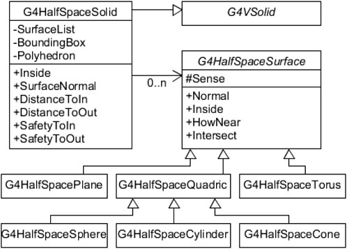
Figure 1. The diagram of classes that implement the half-space solid type. The new half-space solid type G4HalfSpaceSolid is based on the G4VSolid and consists of a collection of half-spaces defined as G4HalfSpaceSurface.
The G4HalfSpaceSolid implements the functions of the G4VSolid interface that are necessary for ray tracking and navigation. The function Inside checks the relative position of a point, that is, inside, outside, or on the boundaries, regarding the solid. The functions DistanceToIn and DistanceToOut compute the distance of a particle entering or exiting this solid along a given direction. The functions SafetyToIn and SafetyToOut estimate the safety (underestimated) distance from a point to enter or exit the solid in any direction.
In the implementation of the function Inside, the bounding box of the solid with a small margin on each side is adopted for a first check of the point position. A point is surely outside the half-space solid when it is outside the bounding box. The points inside the bounding box will be further confirmed by the half-spaces of the solid. Based on (3), a point is outside the half-space solid when it is inside the complement of
Therefore, if
The key functions of G4HalfSpaceSolid are the particle-geometry intersection calculation in DistanceToIn and DistanceToOut. A neutral particle going in a straight trajectory is equivalent to a ray, which has a starting point and a direction vector. For charged particles, the curve trajectory is approximated by chords (Allison et al., 2016), and the intersection calculation method is hence similar to that of a straight trajectory. The intersections of a ray with all boundary surfaces of a half-space solid are performed, and the intersection points outside the solid are discarded because they are not valid. Normally, the distance of the ray to the nearest intersection point is the actual intersection distance. However, some exceptions require special caution. For example, in Figure 2, ray a crosses exactly the intersection line of the cylinder and the plane at Point-1 and enters the solid at Point-2. Point-2 is the correct entry point, but Point-1 might be mistakenly taken because it is the nearest valid answer. To avoid this issue, a probe point with a tiny distance behind Point-1 must be calculated. If the particle is outside the solid after walking in this probe step, Point-2 is the correct answer instead of Point-1.
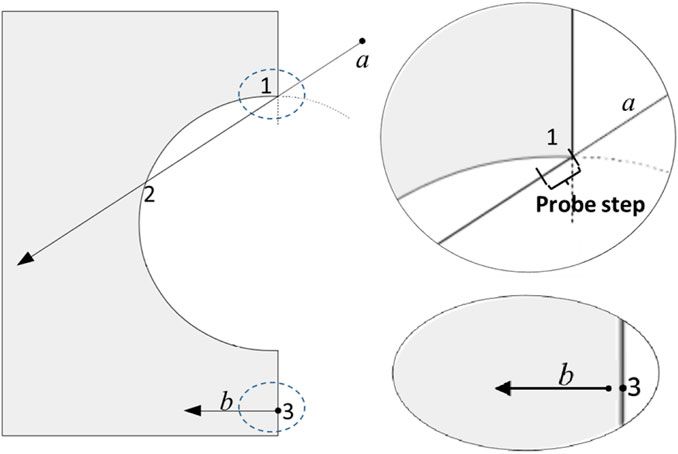
Figure 2. Illustrations of some exceptional cases in calculating the intersection distance of a ray entering and exiting a half-space solid. The gray area represents the solid region.
Another issue is caused by solution tolerance. For example, an intersection point
The safety distances computed by the functions SafetyToIn and SafetyToOut are used to accelerate the geometry tracking. If the distance of a particle to the next collision site is smaller than the safety distance, the collision simulation is invoked without knowing the exact intersection distance to solid boundaries. Therefore, the safety distance must be smaller than the actual intersection distance, and the computational effort of calculating the safety distance should be considerably smaller as well. In SafetyToIn, an underestimated distance from a particle to the bounding box is computed. In SafetyToOut, the minimum isotropic distance of the particle to the boundary surfaces of the half-space solid is calculated. However, calculating the isotropic distance is very computationally expensive for the general quadric and torus surfaces. In these cases, the safety distances are set to 0. This conservative estimation does not affect the correctness of the actual simulation because the intersection calculation will be invoked.
With all these implementations, the G4HalfSpaceSolid is intended to be a kind of generic-purpose solid type for use in neutral or charged particle simulation. To create a G4HalfSpaceSolid in Geant4, the attributes include the bounding box, volume size, and surface area. In addition, the polyhedron is computed and provided in the later modeling method so that all the solids can be visualized in the Geant4 native visualization system. Manually creating a half-space solid is not straightforward; thus, a modeling approach has been developed in this work to generate a half-space solid model automatically from CAD geometries.
3 Half-space solid modeling
In this model approach, the GDML (Chytracek et al., 2006) format has been adopted for the persistence of the half-space solids. The GDML format has been extended to accommodate the half-space solid description. The conversion of CAD solids to half-space solids and an interface for exporting GDML files have been developed.
3.1 GDML extensions
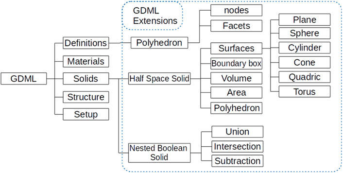
GDML is an application-independent geometry description format based on XML, and it is used as a general format in Geant4 for geometry persistence. It has self-consistent definitions of syntax that are specified in the GDML schema. Therefore, GDML can be extended to describe new solid types as long as the GDML schema is extended. In this work, the description of the half-space solid has been integrated into the GDML schema. As defined in the schema, a GDML file consists of five blocks—Define, the Material, the Solids, the Structure, and the Setup blocks. Extensions have been implemented in the Define and Solids blocks, as shown in Figure 3.
In the Define block, the Polyhedron is a polygon mesh used for visualizing the half-space solid. It is built by a list of nodes defined by three coordinates and a list of triangle facets consisting of three-node indices. In the Solids block, a half-space solid consists of a Surfaces list, which provides detailed definitions of half-spaces by the surfaces. It has a Boundary box defined by an upper and a lower point, a Volume, an Area, and a reference to the Polyhedron. The names of the solids and the polyhedrons must be uniquely given to be used as a reference for other blocks.
A Nested Boolean Solid type has been introduced in the GDML schema. Boolean operators like union, intersection, and subtraction can be used in a nested structure. The description of this solid will be interpreted into G4BooleanSolid in the extended Geant4 GDML parser. In the end, the Geant4 GDML parser has been extended to process the half-space solid information in the extended GDML file and construct a model from it.
3.2 CAD to half-space solid conversion
The conversion of CAD geometry half-space solid has been achieved using McCad (Wu, 1987-1992), which is an open-source MC geometry conversion program based on the Open CASCADE (OCC) library (Open CASCADE Technology, 2015). As the key to the conversion process, an automatic decomposition function that generates a set of splitting surfaces and decomposes the CAD solid using OCC Boolean operations has been implemented. Algorithms have been optimized to detect and sort splitting surfaces, as well as introduce new assistant splitting surfaces.
The conversion process starts with solids. A BRep CAD solid is composed of boundaries, which are also called Faces. The analytic representation of a face is called a Surface. All the surfaces of a solid must be checked in McCad to determine whether they are splitting surfaces. A novel algorithm has been developed in McCad to detect splitting surfaces. Using this algorithm, a BRep solid is meshed into triangle facets employing the OCC library function BRepMesh_ IncrementalMesh. A surface is a splitting surface if it has collisions with at least one facet of other faces or at least two facets of other faces located on different sides of this surface. Taking the two solids in Figure 4 for illustration, Surface-A collides with Facet-B of Face-B; thus, Surface-A is a splitting surface. Facet-E and Facet-F are located on different sides of Surface-C; hence, Surface-C is also a splitting surface.
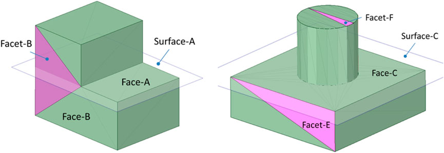
Figure 4. Illustrations of detecting splitting surfaces. The pink triangles are facets, and the transparent planes are splitting surfaces.
In some special cases, the boundary surfaces are not suitable for splitting surfaces even if they pass the detection. For example, in Figure 5A, the cylinder Surface-A is an invalid splitting surface. If cutting the solid by this cylinder, the resultant solid outside the cylinder is not a half-space solid, but a “ghost” solid. An algorithm is provided in McCad to introduce an additional splitting surface. The solid in Figure 5A is cut with the assistant surface Surface-B and Surface-C, and the solid is split into three solids with regular shapes. In addition, optimizing the splitting order can significantly reduce the resultant solids. For example, in Figure 5B, using Surface-C to cut the solid would produce fewer solids than Surface-D. Computational time is reduced in the conversion process by fewer cutting operations. Computational time is reduced in a particle transportation simulation due to fewer solids in the model. More detail about the implementations of these algorithms in McCad is given in (Lu et al., 2017).
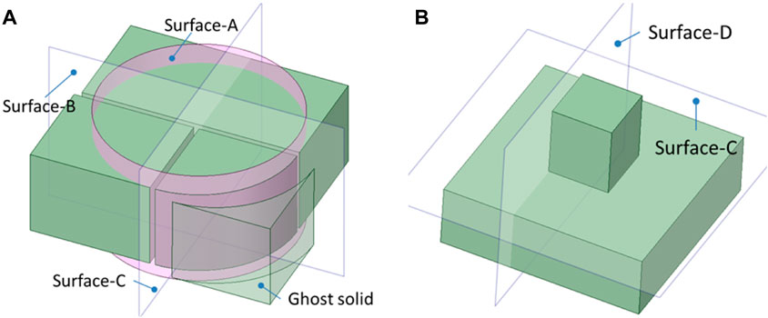
Figure 5. Illustrations of introducing assistant splitting surface in (A) and optimization of the splitting sequence in (B). The transparent planes are splitting surfaces, and the pink surface is an invalid splitting surface.
To make the creation of half-space solids possible for Geant4, a new GDML interface has been developed in McCad to export GDML files. Material compositions are defined by their names and densities and are assigned to a group of CAD solids as attributes. The linking information of a material and a solid is provided in the Structure block of a GDML file. The half-space solids generated from decomposing a CAD solid are exported in the Solids block, and they are united as one nested Boolean solid to represent the original CAD solid. The polyhedrons are produced from the CAD solids for visualization purposes. As a reference, the names of the polyhedrons, materials, and solids are presented uniquely in the GDML file.
As a Geant4 tessellated solid is produced from faceting the CAD solids, it is clear that they can be generated using the OCC function BRepMesh_IncrementalMesh. Therefore, McCad has been implemented with a conversion function for G4TessellatedSolid (Qiu et al., 2016) so that a hybrid model can be produced using together half-space solids and tessellated solids.
4 Tests and verifications
Comparisons have been carried out with the well-validated Geant4 primitive solids and G4TessellatedSolid in modeling both simple and complex geometries to test the new half-space solid. The Geant4 version 10.02 was used for the implementation of G4HalfSpaceSolid, as well as for the test comparisons.
4.1 Test comparisons with Geant4 primitives
As shown in Figure 6, the test comparisons cover all the Geant4 primitive solids supported by the half-space solid. The volume size, the relative position, the safety distance, and the intersection distance are computed, and the results of the primitives are taken as references. Each function is evaluated by testing 106 samples. The points and rays are randomly sampled inside the bounding box with a margin of factor 0.5 in each direction.
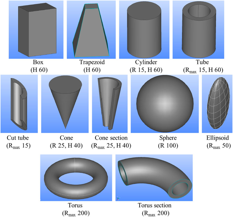
Figure 6. The CSG shapes used to compare the half-space solids and the Geant4 primitive solids. Some of the dimensions are provided (R: radius; H: height; Unit: mm).
The test of the function Inside is considered passed if all the sample points yield consistent results from the two solids. The comparison results of safety and intersection distances are presented by the maximum absolute difference among all the samples. The results are shown in Table 1. Note that the methods for calculating the safety distance in some geometry shapes are different between half-space solids and Geant4 primitives. In this case, the comparisons are ignored, and the results are presented as N/A. The CPU time used for testing all the functions is summed and compared, and the value is presented in Table 1 by ratios taking Geant4 primitives as references.
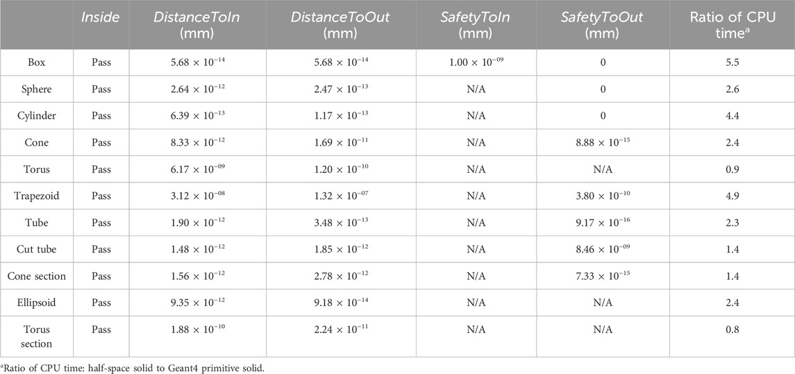
Table 1. Comparison of geometry tracking calculation between half-space solids and Geant4 primitive solids.
The tests of function Inside are passed in all the shapes. For the results of safety and intersection calculations, the differences between half-space solids and primitive solids are mostly below 10−9 mm, which is at the same level as the geometry tolerance. The only exceptional shape is the trapezoid. The reason could be that the trapezoid is defined as a Geant4 primitive G4Trd by the locations of its eight points, while it is defined as a half-space solid by the surface parameters. Due to the limit of the precision, the sloped plane of the trapezoid would not be identical between the two representations, which results in slight differences in the results. Nevertheless, the differences are negligibly small. In general, more CPU time is used for half-space solids than for the Geant4 primitives, which means further optimization of the codes and algorithms is needed for G4HalfSpaceSolid.
4.2 Verification of a complex model
The use of half-space solid type in the modeling of complex geometries is tested using the ITER Benchmark model (Wilson et al., 2008), which is a CAD model of the International Thermonuclear Experimental Reactor (ITER) facility. This CAD model has more than 900 solids, which consist of cylinder, cone, quadric, and torus surfaces. It is converted using McCad and exported to a GDML file. Approximately 3,000 half-space solids are produced in this step. In order to verify this model, a tessellated solid model has been generated using McCad from the same CAD model as half-space solids. Tessellated solids are generated one-to-one with the half-space solid on the same CAD solid so that direct comparison on each solid is allowed, for example, on volume. The precision of the tessellated solid is controlled by a parameter called deflection, which is the relative tolerance of an edge/facet to the original curve surface defined for the tessellation process. The deflection used in this tessellated model is 10−3. These two models are shown in Figure 7. A source has been set up on a sphere surface covering the entire model, and the Geantino particles are generated randomly on the surface. The direction of the particle is identical to the surface normal, pointing to the inside of the sphere. The Geantino particle is a virtual neutral particle that sees all solids as transparent and has no collision during particle transport. In total 1E7 event is simulated, and the track lengths are scored in all solids using the G4PSTrackLength scorer, and the CPU time has also been recorded.
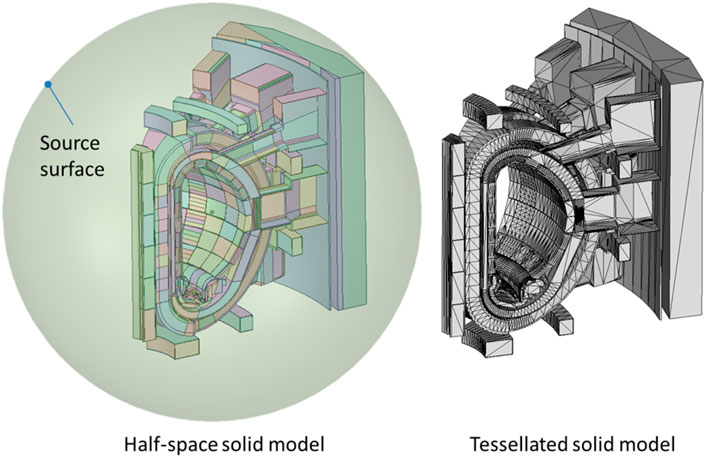
Figure 7. Geometries of the half-space solid model (left) and the tessellated solid model (right). The sphere surface source shown on the left is used to simulate both models.
Due to the large number of solids, the number of facets in the tessellated solid model has exceeded the GDML limitation. To avoid this problem, the tessellated solid model was separated into two models by dividing the solids into two halves. Using the identical source definition, the total Geantino track length in the same spatial region must be identical, regardless of the geometry model. Therefore, this treatment does not affect the track lengths scored on the solids, assuming the tessellated solids are identically defined in the separated model as the full model. However, the simulation time summed up from the two separated models will be underestimated compared to the full model because fewer solids are involved in the particle navigation.
The computational time is shown in Table 2, using one 3.40 GHz processor. The computational performance of the half-space solid model is at least 30% faster than that of the tessellated solid model. This performance could possibly be further improved, for example, by using the well-optimized G4MultiUnion to unite the half-space solids instead of using the nested Boolean solid. In addition, a certain number of particles are lost due to the geometry errors in the high-complexity model. The lost particles in 107 samples are given in Table 2 as well, which shows that the half-space solid model has fewer geometry errors. Note that the lost particles reflect the qualities of the McCad-generated models on complex geometries using two different approaches and do not imply or reflect issues of the G4HalfSpaceSolid and G4TessellatedSolid implementations. The comparison of the track lengths is presented in Figure 8 as ratios, which take the results from the tessellated solid model as references. The ratios are, in general, within ±0.5%. A few solids have ratios of up to 2%. These larger variations are probably due to the geometry difference between the two representations because tessellated solids are facet approximations of CAD solids. The relative error of the half-space solid calculation is provided in Figure 8 as well, with a similar trend found in the calculation of the tessellated solid model. It should be noted that the relative error is higher than the ratio of the track lengths, which is unexpected. The reason why track lengths comparison shows a much lower deviation is likely because the same random number generator and seed are used for the simulation of two models, resulting in source particles generated in the same directions in the two runs.
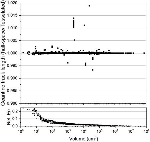
Figure 8. The comparison of track length results in each solid between the half-space solid model and the tessellated solid model. The tessellated solid model has been taken as a reference to calculate the differences. The relative error (Rel. Err.) of the half-space solid calculation is provided.
5 Conclusions
A new approach has been developed for Geant4 to model CAD geometry. In this approach, a new CSG solid type called a half-space solid has been developed to allow the conversion from CAD to CSG solids. It has been implemented as a new solid type in Geant4 version 10.02 code with the mandatory functions. In addition, an automatic conversion approach has been developed in McCad to decompose CAD solids into half-space solids with several optimized algorithms. The GDML format has been extended to accommodate the half-space solid type, with interfaces to export the solids from McCAD and then parse in Geant4 code. With all these developments, the automatic conversion of CAD geometries for Geant4 is fulfilled as a mature workflow.
For test verification, the half-space solid type has been tested by comparisons with Geant4 primitives, and very good agreements have been obtained in most of the solids. A complex CAD model of the ITER facility to compare a half-space solid model and a tessellated solid model. The ratios of results between the two models are, in general, within ±0.5%. Further optimizations are suggested in the future to improve the computation speed of the half-space solid type. This development has been released on Qiu (2024) and linked to Geant4 version 10.02. It is open-source and is available for the Geant4 community. It should be noted that the current developments are based on a previous version of Geant4 and thus need to be updated to the new Geant4 code base. The update and extension of the code will be collaborative work contributed by people interested in this development.
Data availability statement
The original contributions presented in the study are included in the article/Supplementary Material; further inquiries can be directed to the corresponding author.
Author contributions
YQ: conceptualization, data curation, formal analysis, funding acquisition, investigation, methodology, project administration, resources, software, supervision, validation, visualization, writing–original draft, and writing–review and editing.
Funding
The author(s) declare that financial support was received for the research, authorship, and/or publication of this article. Part of this work, supported by the European Communities under contracts of the Association between Euratom and the Karlsruhe Institute of Technology (KIT), was carried out within the framework of the EUROfusion Consortium, funded by the European Union via the Euratom Research and Training Program (Grant Agreement No 101052200—EUROfusion).
Acknowledgments
Special acknowledgments to Dr. Ulrich Fischer and Dr. Lei Lu for providing valuable support during the code development and manuscript reviews. We acknowledge support by the KIT Publication Fund of the Karlsruhe Institute of Technology.
Conflict of interest
The author declares that the research was conducted in the absence of any commercial or financial relationships that could be construed as a potential conflict of interest.
Publisher’s note
All claims expressed in this article are solely those of the authors and do not necessarily represent those of their affiliated organizations, or those of the publisher, the editors, and the reviewers. Any product that may be evaluated in this article, or claim that may be made by its manufacturer, is not guaranteed or endorsed by the publisher.
Author disclaimer
Views and opinions expressed are those of the author(s) only and do not necessarily reflect those of the European Union or the European Commission. Neither the European Union nor the European Commission can be held responsible for them.
References
Allison, J., Amako, K., Apostolakis, J., Arce, P., Asai, M., Aso, T., et al. (2016). Recent developments in Geant4. NIM A 835, 186–225. doi:10.1016/j.nima.2016.06.125
Apostolakis, J., Bandieramonte, M., Bitzes, G., Brun, R., Canal, P., Carminati, F., et al. (2015). Towards a high performance geometry library for particle-detector simulations. J. Phys. Conf. Ser. 608, 012023. doi:10.1088/1742-6596/608/1/012023
Brun, R., and Rademakers, F. (1997). ROOT — an object oriented data analysis framework. Nucl. Instrum. Methods Phys. Res. Sect. A Accel. Spectrom. Detect. Assoc. Equip. 389 (Issues 1–2), 81–86. ISSN 0168-9002. doi:10.1016/S0168-9002(97)00048-X
Chytracek, R., Mccormick, J., Pokorski, W., and Santin, G. (2006). Geometry description Markup Language for physics simulation and analysis applications. IEEE TNS 53 (Issue), 2892–2896. doi:10.1109/tns.2006.881062
Lu, L., Qiu, Y., and Fischer, U. (2017). Improved solid decomposition algorithms for the CAD-to-MC conversion tool McCad. Fusion Eng. Des. 124, 1269–1272. ISSN 0920-3796. doi:10.1016/j.fusengdes.2017.02.040
Open CASCADE Technology (2015). 3D modeling and numerical simulation. Available at: http://www.opencascade.org.
Qiu, Y., Fischer, U., and Lu, L. (2016). “A new Geant4 modeling solution based on CAD geometries,” in Presented at Annual Nuclear Science Symposium and Medical Imaging Conference, Strasbourg, France, Oct. 29 - Nov. 5, 2016 (NSS/MIC).
Qiu, Y. (2024). Geant4-Halfspace-solid [Computer software]. GitHub. Available at: https://github.com/Derek-yfqiu/Geant4-Halfspace-solid.
Sulkimo, J., and Vuoskoski, J. (1996). Particle tracking in sophisticated CAD modelsfor simulation purposes. Nim. A 371, 434–438. doi:10.1016/0168-9002(95)01238-9
Tsige-Tamirat, H. (2001). “On the use of cad geometry for Monte Carlo particle transport,” in Advanced Monte Carlo for radiation physics, particle transport simulation and applications (Germany: Springer), 511–516.
Wilson, P., Feder, R., Fischer, U., Loughlin, M., Petrizzi, L., Wu, Y., et al. (2008). State-of-the-art 3-d radiation transport methods for fusion energy systems. Fusion Eng. Des. 83 (7–9), 824–833. doi:10.1016/j.fusengdes.2008.05.038
Keywords: CAD, CSG, GDML, GEANT4, half-space, McCad
Citation: Qiu Y (2024) New CAD modeling approach in Geant4 with half-space CSG. Front. Nucl. Eng. 3:1400482. doi: 10.3389/fnuen.2024.1400482
Received: 13 March 2024; Accepted: 26 July 2024;
Published: 14 August 2024.
Edited by:
Wei Peng, Tsinghua University, ChinaReviewed by:
Yuetong Luo, Hefei University of Technology, ChinaStewart Boogert, The University of Manchester, United Kingdom
Copyright © 2024 Qiu. This is an open-access article distributed under the terms of the Creative Commons Attribution License (CC BY). The use, distribution or reproduction in other forums is permitted, provided the original author(s) and the copyright owner(s) are credited and that the original publication in this journal is cited, in accordance with accepted academic practice. No use, distribution or reproduction is permitted which does not comply with these terms.
*Correspondence: Y. Qiu, eXVlZmVuZy5xaXVAa2l0LmVkdQ==
 Y. Qiu