 Hazel M. Gardner
 Gyula Zilahi
 James Wade-Zhu
94% of researchers rate our articles as excellent or good
Learn more about the work of our research integrity team to safeguard the quality of each article we publish.
Find out more
BRIEF RESEARCH REPORT article
Front. Nucl. Eng. , 22 January 2024
Sec. Nuclear Materials
Volume 2 - 2023 | https://doi.org/10.3389/fnuen.2023.1332377
This article is part of the Research Topic Women in Nuclear Engineering Research View all 15 articles
Two-micron thick erbium oxide tritium barrier coatings have been prepared by aerosol injection chemical vapor deposition and subsequently irradiated with 33 MeV Au 6+ ions at fluences up to 2.1 × 10¹⁶ Au/m2 at 550°C. Scanning electron microscopy, X-ray diffraction and transmission electron microscopy were used to investigate the coating surface morphologies, phase structures and cross-sectional microstructures as a function of irradiation and thermal treatment. XRD data was also used to extract information about the evolution of lattice strain in the coating. Some of the cubic erbia transformed to the monoclinic phase in the sample that was ion irradiated at temperature, and this was accompanied by a change from columnar to a more equiaxed grain structure. All coatings were found to experience out-of-plane tensile strain, thought to originate from thermal stresses created during coating manufacture. Thermal treatment reduced microstrains present in the as-deposited sample, whilst the cubic-to-monoclinic phase transformation reduced strain in the cubic phase but increased strain in the monoclinic phase.
Erbium oxide (erbia, Er2O3) coatings are being investigated for use in the breeder blanket and tritium extraction system of future fusion power plants owing to their high permeation reduction factor (Nemanič, 2019) and ability to show some degree of resistance to attack by corrosive liquid Li (Pint et al., 2002). However, to perform successfully as a tritium permeation barrier the erbia coating must withstand thermal cycling and remain stable under irradiation during reactor operation.
Erbia has a low temperature cubic (bixbyite) phase with higher temperature monoclinic and hexagonal phases (Zinkevich, 2007; Ushakov et al., 2020), denoted as C, B and H respectively. The phase structure of the erbia affects the properties and performance of the coating. For example, the B phase has higher stability under ion irradiation than the C phase (Tang et al., 2006) but the C phase is harder than the B phase (Li et al., 2012). Studies have shown that coating application method can be tailored to control the phase of as-deposited thin erbia films (Adelhelm et al., 2009; Yan et al., 2019).
Pressure (Guo et al., 2007), temperature (Yan et al., 2019) and ion irradiation (Tang et al., 2006) have all been shown to separately induce cubic-to-monoclinic phase transformations in erbia. This work investigates the combined thermal and ion irradiation response of cubic erbium oxide coatings produced by chemical vapor deposition (CVD), at temperatures and irradiation damage levels that are relevant to breeder blanket operating conditions.
Grade 91 steel substrate discs were grit blast in preparation for the coating application process. Er2O3 coatings were deposited on one side of the substrate using aerosol injection CVD with Er (tmhd)3 precursor and oxygen as a reactive gas. A 2-micron thick erbium oxide coating was deposited at a substrate temperature of 600–700°C, with a total process time of 1–1.5 h. Exact details of precursor partial pressures, deposition temperatures and process times are proprietary to the coating manufacturer (ATL, High Wycombe, United Kingdom).
The coating was ion irradiated at the Dalton Cumbria Facility with 33 MeV Au 6+ ions at fluences up to 2.1 × 10¹⁶ Au/m2 at 550°C, with the incident ions normal to the coated surface. The Monte Carlo program SRIM (Ziegler and Biersack, 1985) was used to estimate the displacement damage distribution under these irradiation conditions. The peak in the displaced atom damage distribution occurs in the steel substrate at a sample depth of 3.5 micron (1.5 microns beyond the coating substrate interface). This corresponds to a peak displacement damage level in the steel of 55 displacements per atom (dpa) at a fluence of 2.1 × 10¹⁶ Au/m2. This is approximately the targeted lifetime dose of the DEMO second generation breeder blanket (Federici et al., 2019). The displacement damage level within the 2 micron coating layer is 20–25 dpa. During the irradiation, a small square of the sample was blanked by a mask such that this region of the sample experienced the same temperature without irradiation. This region of sample is referred to as “irradiated (blanked).” The region of sample that was not blanked by the mask is referred to as “irradiated (exposed).”
The as-deposited, irradiated (blanked) and irradiated (exposed) samples were each analyzed using scanning electron microscopy (SEM), X-ray diffraction (XRD) and transmission electron microscopy (TEM). Secondary electron SEM images were collected from the surface of all three samples using a Tescan Mira3 XMH scanning electron microscope. XRD measurements were made using a Rigaku Smartlab X-ray diffractometer. Cu Kα radiation was used for the as-deposited sample whereas Co Kα radiation was used for the irradiated (blanked) and irradiated (exposed) samples, due to instrument availability. A fixed, 6° angle of incidence was used for the as-deposited sample; a 3° angle of incidence was used for the irradiated (blanked) and irradiated (exposed) samples.
Cross sections were prepared for TEM examination from the as-deposited and both irradiated samples using a focused ion beam. The microstructures were examined using a FEI Tecnai F20 G2 S—Twin FEG-scanning TEM.
Figure 1 shows representative regions of the coated surface of the as-deposited sample and the irradiated (blanked) and irradiated (exposed) samples. The coating morphology was consistent across all three samples, and gaps can be observed in the regions where adjacent coating nodules have nucleated and grown together. XRD spectra collected from the samples are shown in Figure 2, along with simulated spectra that were plotted using data from the Materials Project (Jain et al., 2013). Comparison of the experimental data with the simulated spectra shows that the peaks marked with a circle on Figure 2 in the as-deposited and irradiated (blanked) data match those expected for the cubic erbia phase. In all samples, peaks present at Q = 3.097 1/Å and Q = 4.379 1/Å can be attributed to BCC Fe phase, which originate from the substrate. No other peaks were identified as relating to the substrate or substrate oxides. In the ion irradiated (exposed) sample, additional peaks are present at Q (1/Å) = 2.109, 2.151, 2.274, 3.632, 3.769, and 3.886, which correspond to peaks expected for the monoclinic phase. This suggests that the ion irradiation has induced a phase change.
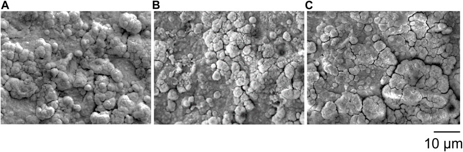
FIGURE 1. SEM images of the surface of the erbia coatings in the (A) as-deposited, (B) ion irradiated (blanked) and (C) ion irradiated (exposed) regions.
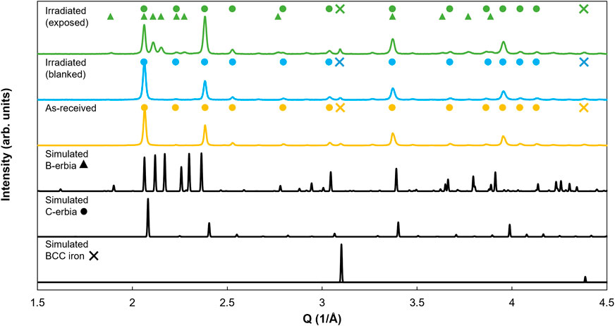
FIGURE 2. XRD patterns of erbium oxide coated Grade 91 steel in the as-deposited, ion irradiated (blanked) and ion irradiated (exposed) state. Simulated patterns for BCC iron, cubic C-erbia and monoclinic B-erbia are included for reference. All patterns have been normalized to the highest peak intensity.
The ratio of the intensity of the peak at Q = 2.061 1/Å to the peak at Q = 2.383 1/Å changed between the three samples. These peak positions correspond to the (222) and the (400) peaks for the cubic phase, respectively. The (222) peak is the highest intensity peak in the simulated spectrum for the cubic erbia phase, as well as in the as-deposited and ion irradiated (blanked) spectra. For the irradiated (exposed) sample, the (222) peak is less intense than the (400) peak. Multiple mechanisms could be contributing to this change in peak intensity in the irradiated (exposed) sample. For example, it is possible that point defects generated in the irradiated (exposed) sample are favoring diffusion and crystal re-ordering of the Er/O atoms, such that a change in preferred grain orientation from (222) to (400) occurs in the cubic erbia. A similar change in preferred grain orientation from (222) to (400) has been observed in H permeation studies in cubic erbia (Chikada et al., 2011). First principles modelling showed that interactions between the H and O/Er atoms resulted in movement of O/Er atoms, enabling change in grain orientation (Mao et al., 2020). Another mechanism that could be contributing is irradiation-induced grain growth of the (400) oriented grains in the cubic phase, resulting in an increase in intensity of the (400) peak relative to the (222) peak. Further work is needed to fully outline all mechanisms at play, and determine which mechanisms are dominant.
Two different types of lattice strain can be extracted from XRD spectra. The first type manifests as a shift in position of the XRD peaks and occurs when the strain extends over the whole lattice. The second, known as microstrain, results in broadening of the XRD peaks and occurs over only a few lattice spacings (Dolabella et al., 2022). Microstrain is caused by defects such as dislocations and vacancies, which locally distort the lattice (Maniammal et al., 2017).
The major peaks for each of the measured spectra in Figure 2 were all shifted to the left relative to the corresponding peak position in the simulated spectra. Since the spectra are plotted in reciprocal space, this shift indicates that all samples were under a slight tensile strain. Because the XRD measurements have been taken in reflection mode, the peak shift measurements were affected by the out-of-plane strain components. Cubic erbia has a coefficient of thermal expansion (CTE) of 6.5 × 10⁻⁶ K−1 (Liu et al., 2010) whereas Grade 91 steel has a CTE of ∼13 × 10−6 K−1 (Norajitra, 2014). This difference in CTE caused the coating to be put under an in-plane compressive stress during cooling from deposition temperature to room temperature. This set up out-of-plane tensile strains, as a result of Poisson’s ratio, in the as-deposited coating.
In additional to the thermal strain caused by the difference in CTE between the coating and the steel, microstrains are present within the coating grains. Microstrain within the coatings manifest as the broadening of peaks in the XRD spectrum. However, change in crystallite size can also result in peak broadening. Williamson and Hall (Williamson and Hall, 1953) identified that the microstrain (ε) and crystallite size (L) contributions to peak broadening vary differently as a function of the diffraction half angle, θ, as described by Eq. 1. This enables the microstrain contribution to be extracted.
where β is the FWHM in radians of the peak at diffraction angle, 2θ, Ksize is a shape factor set to 0.94 (Pang et al., 2009) and Kstrain is set to 4 for isotropic growth (Pang et al., 2009).
To obtain β, the XRD spectra were fitted using split pseudo-voigt function with B-spline background fit, using the Rigaku SmartLab Studio II software. For each sample, by plotting βCosθ against 4Sinθ for the peaks of each phase, the microstrain can be extracted from the gradient of the plot, as seen in Figure 3. Peak prominence was used as a metric to determine which peaks should be included in the Williamson-Hall plots; all peaks with a value of prominence greater than 0.035 (for normalized spectra) were included. A least squares fit was used to determine the gradient, and the error bars plotted on the microstrain values represent the standard deviation associated with the gradient of the fit.
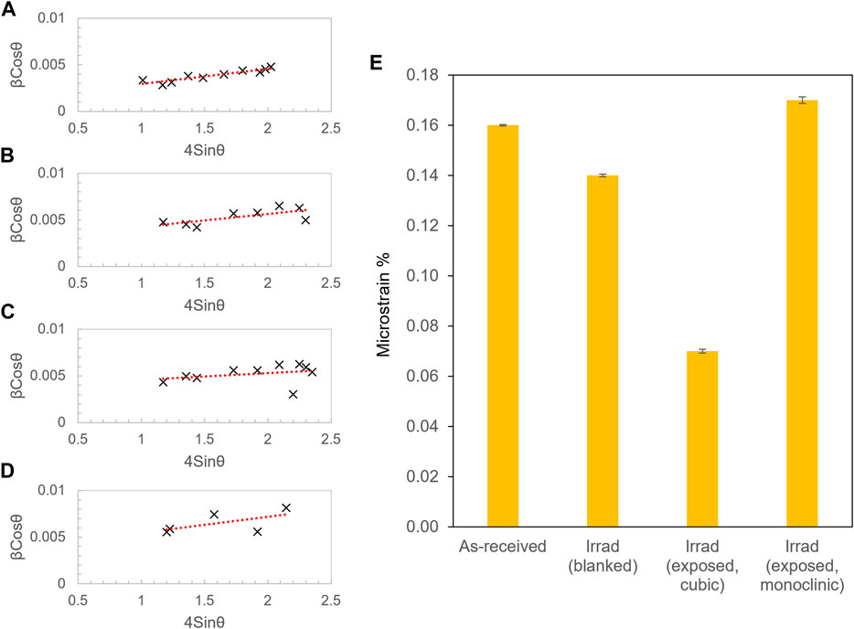
FIGURE 3. Williamson Hall (W-H) plots for (A) as-deposited, (B) ion irradiated (blanked), (C) ion irradiated (exposed, cubic erbia) and (D) ion irradiated (exposed, monoclinic erbia) erbia coated samples. (E) displays the microstrain extracted from each of the W-H plots.
It can be seen from Figure 3E that the microstrain was reduced in the blanked region of the irradiated sample compared to the as-deposited sample. This is likely to be a result of thermal annealing of the residual stresses through reduction of defect density, especially given that the ion irradiations were conducted at temperatures close the deposition temperature of the coatings (Tirrad = 550°C vs. Tcvd ∼650°C) over much longer time periods (53 h vs. ∼1–2 h). The microstrain in the cubic phase of the irradiated (exposed) sample was further reduced compared to the blanked sample. By contrast, the microstrain in the monoclinic phase of the irradiated (exposed) sample was much higher. Since microstrain results from the local lattice distortions caused by defects, Figure 3E suggests that the monoclinic phase formed in the irradiated (exposed) sample is highly defective, while the cubic phase that remains has a much lower defect density. The defects present in the monoclinic phase are likely to be a combination of irradiation induced defects and the increase in defect density that results from the ∼9% volume contraction associated with the cubic-to-monoclinic transformation.
The microstructural changes that occur in the irradiated (blanked) and irradiated (exposed) coatings can be directly observed in the cross-sectional TEM images in Figure 4. The as-deposited coating seen in Figure 4A, B is crack-free and has a fine columnar microstructure typical of CVD coatings. The surface roughness of the substrate can be seen to affect the coating growth and morphology. For example, the arrows on Figure 4B indicate roughness on the steel substrate that has nucleated regions of coating growth, which have subsequently impinged on each other as they have grown. This often leads to the formation of columnar pores, as demonstrated by the white lines emanating from the substrate surface at consecutive points along the coating. The cross-sectional TEM reveals how the substrate surface roughness gives rise to the nodular coating morphology observed in Figure 1.
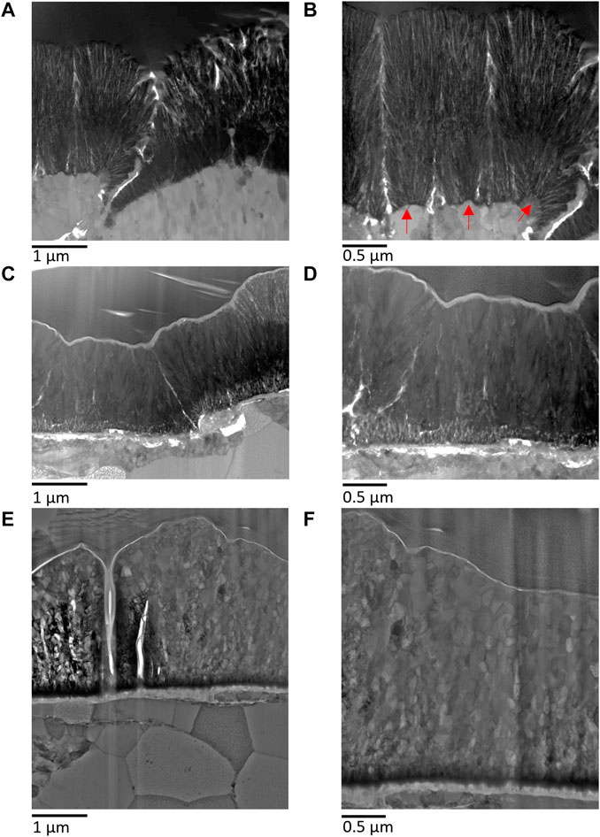
FIGURE 4. Cross sectional TEM images of the erbium oxide coated Grade 91 steel in the (A, B) as-deposited, (C, D) ion irradiated (blanked) and (E, F) ion irradiated (exposed) state.
The microstructure of the irradiated (blanked) sample in Figure 4C, D was the result of thermal annealing of the as-deposited structure. The grains were still columnar in shape. While it was not possible to quantitatively analyse the grain size in these micrographs, visual inspection shows that the grain size was larger in the irradiated (blanked) sample than the as-deposited sample. This observed grain growth provides confirmation of the occurrence of thermal annealing effects and their contribution to the decrease in microstrain in the irradiated (blanked) sample.
The equiaxed grain structure of the irradiated (exposed) sample in Figures 4E, F was markedly different to the columnar grain structure of the as-deposited and irradiated (blanked) coatings. A combination of the cubic-to-monoclinic phase transformation and annealing/grain growth of the remaining cubic phase has resulted in this microstructure.
The microstructures in Figure 4 also reveal changes at the coating-substrate interface, which warrant further investigation. However, this is not the focus of this study and will be reported on in a future publication.
The out-of-plane tensile lattice strains measured using XRD have been caused by in-plane thermal stresses created in the coating during manufacture. It is important to control the stress state of the coating since it can dictate the phases formed. For example, presence of a compressive stress during coating growth has been reported to favor monoclinic erbia over cubic erbia (Adelhelm et al., 2009), since the monoclinic phase can be formed at high pressure (Guo et al., 2007). Use of interlayers is currently being explored by the authors to reduce the difference in CTE between the coating and substrate, thus reducing the thermal stress generated in the coating upon cooling from the deposition temperature. Coating application method can also be controlled to tailor the stress state of the coating, thus influencing the coating microstructure and performance (Adelhelm et al., 2009).
The XRD data alone is insufficient to determine that the monoclinic erbia phase is only formed in the irradiated (exposed) sample, due to overlapping cubic and monoclinic erbia peaks and the phase fraction detection limit of the XRD instrument. However, when the XRD data from Figure 2 is taken in combination with the microstructural information from Figure 4, the change from columnar to equiaxed microstructure that occurs only after ion irradiation supports the idea that the phase change is induced by ion irradiation at 550°C, for a damage level of 20–30 dpa. Tang et al. (Tang et al., 2006) observed a cubic-to-monoclinic transformation in erbium oxide under 300 keV Kr++ ion irradiation at cryogenic temperature (−153°C) when the damage exceeded ∼15 dpa, and proposed that the phase transformation resulted from a combination of intracascade transformation and damage accumulation. The higher irradiation temperature of 550°C in this study means that the erbia is in the defect cluster swelling regime between Stage I and III recovery, whereas in the study by Tang et al. (Tang et al., 2006) the sample was at cryogenic temperature which is close to the onset of stage I recovery (Zinkle and Snead, 2014). A greater level of defect recovery is occurring at 550°C compared to −153°C, due to a greater number of mobile interstitials. This may reduce the levels of damage accumulation contributing to the phase change in this study compared to the study by Tang et al. (2006).
A previous study (Yan et al., 2019) on the thermally induced cubic-to-monoclinic phase transformation in erbia coatings reports that there is a competition between grain growth and phase transformation. For example, in the case where groups of grains of the cubic phase exist, the energy barrier for phase transformation to the monoclinic phase is higher than the energy barrier for grain growth. In the irradiated (blanked) sample, grain growth occurs in preference to phase transformation whereas in the irradiated (exposed) sample, phase transformation is observed. It is proposed that ion irradiation damage combined with temperature lowers the energy barrier for the cubic-to-monoclinic phase transformation. Further work is needed to understand the role of irradiation temperature in the cubic-to-monoclinic phase transformation of erbium oxide.
This study has shown that some of the cubic erbium oxide phase transforms to the monoclinic phase under ion irradiation at 550°C, for a damage level of 20–30 dpa, meaning that cubic erbium oxide is not stable under these conditions. The monoclinic erbia phase has previously been shown to be more stable under ion irradiation than the cubic phase (Tang et al., 2006). However, the permeation reduction factor of monoclinic erbia is reported to be an order of magnitude lower than that of cubic erbia (Brendel et al., 2011). Furthermore, this study suggests that monoclinic erbia transformed from the cubic phase has a high defect density, which is likely to cause an undesirable increase in tritium retention, with defects potentially acting as trap sites in the coating. The findings of this work may have implications on the use of erbium oxide as a tritium barrier in fusion environments. However, further investigations are needed to understand the permeation performance of as-grown monoclinic erbia compared to cubic to understand whether a compromise can be reached between improved irradiation resistance and acceptable reduction in tritium permeation with minimal tritium trapping.
The data presented in the study are publicly available. The data can be found here: https://doi.org/10.14468/we5q-sm15.
HG: Writing–original draft, Writing–review and editing. GZ: Writing–review and editing. JW-Z: Writing–review and editing.
The author(s) declare financial support was received for the research, authorship, and/or publication of this article. HG, GZ and JW-Z acknowledge funding from EPSRC grant EP/W006839/1. The research used UKAEA’s Materials Research Facility, which has been funded by and is part of the UK’s National Nuclear User Facility and Henry Royce Institute for Advanced Materials.
We acknowledge the support of The University of Manchester’s Dalton Cumbrian Facility (DCF), a partner in the National Nuclear User Facility, the EPSRC United Kingdom National Ion Beam Centre and the Henry Royce Institute. We recognize Dr. Samir de Moraes Shubeita, Dr. Andy Smith, Dr. Jack Haley, Dr. Max Rigby Bell for their assistance during the ion irradiation experiment. The authors thank Dr. Stuart Robertson for carrying out the TEM sample preparation and imaging at Loughborough Materials Characterisation Centre.
The authors declare that the research was conducted in the absence of any commercial or financial relationships that could be construed as a potential conflict of interest.
All claims expressed in this article are solely those of the authors and do not necessarily represent those of their affiliated organizations, or those of the publisher, the editors and the reviewers. Any product that may be evaluated in this article, or claim that may be made by its manufacturer, is not guaranteed or endorsed by the publisher.
Adelhelm, C., Pickert, T., Balden, M., Rasinski, M., Plocinski, T., Ziebert, C., et al. (2009). Monoclinic B-phase erbium sesquioxide (Er2O3) thin films by filtered cathodic arc deposition. Scr. Mater. 61 (8), 789–792. doi:10.1016/j.scriptamat.2009.06.031
Brendel, A., Adelhelm, C., Werkstetter, M., Pickert, T., Ertl, K., Balden, M., et al. (2011). “Phase formation of Erbia coatings on EUROFER 97, phase stability and deuterium permeability,” in Proceedings of the 13th International Workshop on Plasma-Facing Materials and Components for Fusion Applications and 1st International Conference on Fusion Energy Materials Science, Germany, September 2011.
Chikada, T., Suzuki, A., Adelhelm, C., Terai, T., and Muroga, T. (2011). Surface behaviour in deuterium permeation through erbium oxide coatings. Nucl. Fusion 51 (6), 063023. doi:10.1088/0029-5515/51/6/063023
Dolabella, S., Borzì, A., Dommann, A., and Neels, A. (2022). Lattice strain and defects analysis in nanostructured semiconductor materials and devices by high-resolution X-ray diffraction: theoretical and practical aspects. Small Methods 6 (Issue 2), e2100932. doi:10.1002/smtd.202100932
Federici, G., Boccaccini, L., Cismondi, F., Gasparotto, M., Poitevin, Y., and Ricapito, I. (2019). An overview of the EU breeding blanket design strategy as an integral part of the DEMO design effort. Fusion Eng. Des. 141, 30–42. doi:10.1016/J.FUSENGDES.2019.01.141
Guo, Q., Zhao, Y., Jiang, C., Mao, W. L., Wang, Z., Zhang, J., et al. (2007). Pressure-induced cubic to monoclinic phase transformation in erbium sesquioxide Er2O3. Inorg. Chem. 46 (15), 6164–6169. doi:10.1021/ic070154g
Jain, A., Ong, S. P., Hautier, G., Chen, W., Richards, W. D., Dacek, S., et al. (2013). Commentary: the materials project: a materials genome approach to accelerating materials innovation. Am. Inst. Phys. Inc 1 (Issue 1). doi:10.1063/1.4812323
Li, X., Wu, P., Qiu, H., Chen, S., and Song, B. (2012). Crystallization behavior and mechanical properties of erbium oxide coatings fabricated by pulsed magnetron sputtering. Thin Solid Films, 520(6), 2316–2320. doi:10.1016/j.tsf.2011.09.053
Liu, S., Ju, X., Xin, Y., Qiu, J., Li, T., and Cao, J. L. (2010). Investigation of coating CLAM steel substrates with erbium oxide by a magnetron sputtering method. Fusion Eng. Des. 85 (7–9), 1401–1405. doi:10.1016/j.fusengdes.2010.03.059
Maniammal, K., Madhu, G., and Biju, V. (2017). X-ray diffraction line profile analysis of nanostructured nickel oxide: shape factor and convolution of crystallite size and microstrain contributions. Phys. E Low-Dimensional Syst. Nanostructures 85, 214–222. doi:10.1016/j.physe.2016.08.035
Mao, W., Wilde, M., Chikada, T., Fukutani, K., Matsuzaki, H., and Terai, T. (2020). Hydrogen isotope role in the crystal orientation change of erbium oxide coatings. J. Nucl. Mater. 528, 151871. doi:10.1016/j.jnucmat.2019.151871
Nemanič, V. (2019). Hydrogen permeation barriers: basic requirements, materials selection, deposition methods, and quality evaluation. Nucl. Mater. Energy 19, 451–457. doi:10.1016/j.nme.2019.04.001
Norajitra, P. (2014). Development for a future fusion power plant. Deutschland: KIT Scientific Publishing.
Pang, X., Gao, K., Luo, F., Emirov, Y., Levin, A. A., and Volinsky, A. A. (2009). Investigation of microstructure and mechanical properties of multi-layer Cr/Cr2O3 coatings. Thin Solid Films 517 (6), 1922–1927. doi:10.1016/J.TSF.2008.10.026
Pint, B. A., Devan, J. H., and Distefano, J. R. (2002). Temperature limits on the compatibility of insulating ceramics in lithium. J. Nucl. Mater., 307–311. doi:10.1016/S0022-3115(02)01224-2
Tang, M., Lu, P., Valdez, J. A., and Sickafus, K. E. (2006). Ion-irradiation-induced phase transformation in rare earth sesquioxides (Dy 2O 3, Er 2O 3, Lu 2O 3). J. Appl. Phys. 99 (6). doi:10.1063/1.2184433
Ushakov, S. V., Hayun, S., Gong, W., and Navrotsky, A. (2020). Thermal analysis of high entropy rare earth oxides. Materials 13 (14), 3141. doi:10.3390/ma13143141
Williamson, G. K., and Hall, W. H. (1953). X-ray line broadening from filed aluminium and wolfram. Acta Metall. 1 (1), 22–31. doi:10.1016/0001-6160(53)90006-6
Yan, D., Wu, P., Zhang, Y., Zhang, S., Yang, J., Li, Y., et al. (2019). Effect of Er interlayer on microstructure, composition, electrical and mechanical properties of erbium oxide coating on steel. Appl. Surf. Sci. 498, 143750. doi:10.1016/j.apsusc.2019.143750
Ziegler, J. F., and Biersack, J. P. (1985). “The stopping and range of ions in matter,” in Treatise on heavy-ion science (Berlun, Germany: Springer), 93–129.
Zinkevich, M. (2007). Thermodynamics of rare earth sesquioxides. Prog. Mater. Sci. 52 (4), 597–647. doi:10.1016/j.pmatsci.2006.09.002
Keywords: fusion energy, ceramic coatings, erbium oxide, ion beam irradiation, microstructure evolution, chemical vapor deposition, phase transformation
Citation: Gardner HM, Zilahi G and Wade-Zhu J (2024) Investigating the thermal and irradiation stability of chemical vapor deposited erbium oxide tritium barrier coatings for Li breeder blanket applications. Front. Nucl. Eng. 2:1332377. doi: 10.3389/fnuen.2023.1332377
Received: 02 November 2023; Accepted: 18 December 2023;
Published: 22 January 2024.
Edited by:
Anne Campbell, Oak Ridge National Laboratory (DOE), United StatesReviewed by:
Jacques Lechelle, Commissariat à l’Energie Atomique et aux Energies Alternatives (CEA), FranceCopyright © 2024 Gardner, Zilahi and Wade-Zhu. This is an open-access article distributed under the terms of the Creative Commons Attribution License (CC BY). The use, distribution or reproduction in other forums is permitted, provided the original author(s) and the copyright owner(s) are credited and that the original publication in this journal is cited, in accordance with accepted academic practice. No use, distribution or reproduction is permitted which does not comply with these terms.
*Correspondence: Hazel M. Gardner, aGF6ZWwuZ2FyZG5lckB1a2FlYS51aw==
Disclaimer: All claims expressed in this article are solely those of the authors and do not necessarily represent those of their affiliated organizations, or those of the publisher, the editors and the reviewers. Any product that may be evaluated in this article or claim that may be made by its manufacturer is not guaranteed or endorsed by the publisher.
Research integrity at Frontiers
Learn more about the work of our research integrity team to safeguard the quality of each article we publish.