 Yoshiaki Oka
95% of researchers rate our articles as excellent or good
Learn more about the work of our research integrity team to safeguard the quality of each article we publish.
Find out more
REVIEW article
Front. Nucl. Eng. , 29 November 2023
Sec. Nuclear Reactor Design
Volume 2 - 2023 | https://doi.org/10.3389/fnuen.2023.1272766
This article is part of the Research Topic Reviews In Fission and Reactor Design View all 4 articles
SCWR (supercritical water cooled reactor) is one of the Generation IV reactors. This review summarizes the results of SCWR design concept development through numerical simulations carried out by the author-led team at the University of Tokyo and Waseda University from 1989 to 2014. They are core design, subchannel analysis, statistical thermal design, fuel rod design, development of fuel integrity criteria, plant system and heat balance, plant dynamics analysis, plant control, startup system, stability analysis, safety principle, safety criteria, safety analysis, transient subchannel analysis and fast reactor SCWR. A brief summary of experimental results on thermal hydraulics, materials and water chemistry follows. Discussion includes SCPR study by Japanese BWR manufacturers, comments on the 2005 INEEL SCWR report, misconceptions about SCWR and commercialization challenges. The SCWR is an innovation in light water reactors based on supercritical coal-fired power plant technology that has been in use worldwide for over half a century. This review covers most of the SCWR design and analysis. For researchers, it is a good subject to understand the design and analysis of light water reactors.
SCWR (supercritical water cooled reactor) is one of six generation IV reactors which are promoted by USDOE(United States Department of Energy); since 2001 and then by Generation IV international forum (GIF). The author conducted SCWR research at the University of Tokyo and Waseda University from 1989 to 2014. This review describes the SCWR concept development by numerical simulation.
Figure 1A shows the phase diagram of water. The critical point of water is 22.1 MPa, 374°C. The boiling phenomenon disappears when the liquid is pressurized above the critical pressure, 22.1 MPa. There is no distinction between water and steam in the supercritical state, but the fluid above this temperature and pressure is called supercritical steam. Figure 1B shows the change of the specific heat with temperature at 24MPa and 7 MPa. Figure 1C shows the change of the density with temperature. At 7 MPa, the specific heat shows a peak at the boiling point (286°C) and the density decreases discontinuously. Heat is removed well by boiling. At 24 MPa, the specific heat peaks around the pseudo-critical temperature (approximately 382C at 24 MPa) and the density continuously decreases significantly. At supercritical pressure, heat is removed well when water is heated across the pseudo-critical temperature.
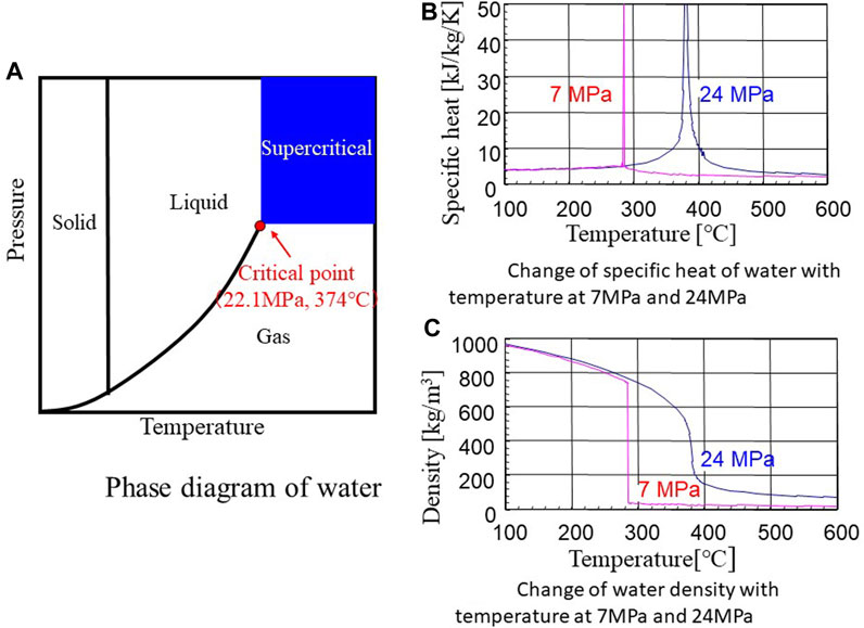
FIGURE 1. (A) Phase diagram of water. (B) Change of specific heat of water with temperature at 7MPa and 24 MPa. (C) Change of water density with temperature at 7MPa and 24 MPa. Source: Oka 2011a.
It should be noted that supercritical steam is different from superheated steam. Superheated steam is steam heated above boiling temperature at subcritical pressure. To produce superheated steam, steam must be separated from water.
Figure 2 shows the concept of SCWR. SCWR adopts once-through direct coolant cycle. This is an advantage of SCWR over LWR in terms of plant system simplification. The reactor coolant is pressurized to 25 MPa by main coolant pumps and delivered to the reactor pressure vessel (RPV). It cools the core. Hot coolant from the RPV is supplied to the steam turbine to generate electricity. The inlet coolant temperature is 280°C and the average outlet coolant temperature is 500°C. The inner walls of the RPV, including the upper dome are cooled by the inlet coolant as a PWR. A thermal sleeve will be provided inside the supercritical steam outlet nozzle to reduce thermal stress. There are two coolant lines, but one of which is shown in the figure. There are no recirculation lines and steam-water separators. Since there is no need to recirculate the reactor coolant as in a BWR (boiling water reactor), the reactor coolant flow rate is approximately one-tenth that of a BWR. The RPV is similar to the PWR and smaller than the BWR. Control rods are inserted from the top of the RPV. The control rod drive mechanism is similar to that of PWR.
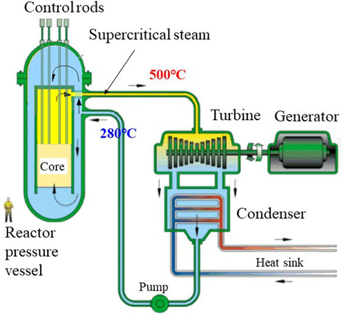
FIGURE 2. Concept of SCWR. Source: USDOE 2002.
At supercritical-pressure, entire reactor coolant becomes supercritical steam when heated in the core. SCWR is the once through coolant cycle, while LWRs require recirculation of hot reactor coolant. This is the advantage of SCWR over LWR (light water reactor) in water chemistry and in controlling corrosion of structural materials. The entire reactor coolant is purified at low temperatures after condensation. That is the practice of supercritical fossil-fired power plants. This is not possible in LWRs where hot reactor coolant is necessarily circulated. LWRs have suffered from SCC (stress corrosion cracking) for many years. It will be easier to deal with SCC in SCWR than LWRs.
The specific volume of supercritical steam is smaller than that of subcritical steam. The specific enthalpy of supercritical steam is higher than that of subcritical steam. The figures are 0.01114 m3/kg and 3166 kJ/kg at 500°C and 250bar, while they are 0.02741 m3/kg and 2273 kJ/kg at 286°C and 70bar. When using supercritical steam instead of subcritical steam, the specific volume decreases by 41% and the specific enthalpy increases by 39%. Turbines and main steam lines for supercritical steam are more compact than those using subcritical steam. Recirculation pumps, their piping, steam separators and dryers of a BWR and steam generators and primary coolant loops of a PWR become unnecessary. SCWRs have better thermal efficiency than LWRs, but this advantage is of secondary importance in nuclear power plants because the fuel cost is a smaller percentage than in fossil-fired power plants. The advantage of SCWR over LWRs are gained in terms of plant simplification and compactness. This decreases the capital cost of SCWR. This is important in the deregulated market economy that power companies in the West have to face.
Boilers have evolved into circular boilers, water tube boilers and once-through boilers. Both circular boilers and water tube boilers operate at subcritical pressure. Water level exists. Once-through boilers operate at supercritical pressure. Water level disappears. LWR is a kind of circular boilers that circulates coolant. LWRs were developed in the United States in the 1950s and early 1960s, based on subcritical pressure fossil-fired power plant technologies. Later, supercritical fossil-fired power plants were developed. The first commercial supercritical coal fired power plant, Philo 6 (125 MWe, 31 MPa, 621°C) began operation in 1957 in the United States. Anegasaki Unit 1, Japan’s first commercial supercritical FPP, started operation in 1967 with a rated output of 600 MWe, a pressure of 24.1 MPa, and a temperature of 538C. In Japan ultra-supercritical fossil-fired power plants have been developed to save on imported fuel, which is expensive. Kawagoe unit 2 (700 MWe, 31 MPa, 593°C) started operation in 1989. Tachibanawan unit1 (1050 MWe, 25 MPa, 610°C) started operation in 2001. SCWR is a type of once-through boiler. Key SCWR components such as coolant pumps, turbines and steam lines exist on a commercial scale. We have also accumulated operational experience in fields such as water chemistry. SCWR is the natural evolution of LWR.
The author started SCWR design study at the University of Tokyo in the late 1980s, when working on steam cooled fast reactor. The author asked a graduate student to increase the steam density. He replied that there was no pressure. The steam table used in the study contained only subcritical pressure data. After learning about the existence of supercritical water, the author comes up with the idea that BWR will be simplified. The author started researching conceptual design within a research group at the University of Tokyo. The result was presented at the ANP92 international conference held in Tokyo in 1992 (Oka 1992). The economic advantages of SCWR were introduced in a paper at the Pacific Basin Nuclear Conference held in Kobe in 1996 (Oka 1996). Since then, the potential of SCWR has become known internationally. It was in 2000 that SCWR research became popular around the world. The HPLWR (High Performance Light Water Reactor) program started in Europe in 2000 with EU funding. In 2000, the author started an international symposium on supercritical water reactors (SCR symposium, later ISSCWR symposium) (Oka 2000). Papers were presented from Japan, Germany, Canada, South Korea, and other countries. USDOE started the Generation IV Reactor Forum in 2000. SCWR was selected as one of six Generation IV reactors in 2002. SCWR researchers around the world, including us, have presented their research results at ISSCWR symposiums and international conferences on nuclear engineering.
The results of our conceptual design research were published in the first book in 2010 (Oka 2010). Experimental study of thermal hydraulics, materials and water chemistry as well as the design study of fast reactor version of SCWR were conducted in collaboration with the researchers of the universities and the research institutes in Japan with the competitive funding from our ministry, MEXT (Ministry of Education, Culture, Sports, Science and Technology) between 2005 and 2014. The experimental results and the results of SCWR design studies after the first volume are summarized in the second volume in 2014 (Oka 2014). The author retired from the University of Tokyo in 2010 and worked at Waseda university between 2010 and 2014. The author retired from Waseda University in 2014 and served as chairman of the Japan Atomic Energy Commission. Since then, the author has been interested in issues between nuclear energy utilization and society. The author did not continue SCWR research after 2014. This paper reviews our research up to 2014. SCWR research continues at Waseda University by professor Yamaji, one of the authors of the first book.
Our SCWR reactors have been named SCLWR, SCLWR-H, Super LWR, etc., for thermal reactors, and SCFBR, SCFBR-H, Super FR, etc., for fast reactors. This review uses the name SCWR. Thermal neutron spectrum SCWR uses UO2 fuel. Fast spectrum SCWR uses MOX (mixed oxide) fuel. In terms of fuel availability, thermal reactor SCWRs are more realistic than fast reactors. SCWR means a thermal reactor in this review.
The author was invited to talk the results of the SCWR research at Joint ICTP-IAEA Course on Science and Technology of Supercritical Water-Cooled Rectors (SCWRs) held at the International Center for Theoretical Physics, Trieste, Italy in 2011. The outline of the design study can be understood from the presentation materials (Oka 2011a; Oka2011b). The slides of the references (Oka 2011a; Oka2011b) are referred in this review, because the total number of figures and tables is limited. The SCWR design and analysis methodology is very similar to that of LWRs. This review helps readers understand the elements of light water reactor design and analysis. The study is a good subject for raising human resources.
The SCWR is a new nuclear reactor that has never been built before. The goal of reactor concept development is to find a simple reactor design for supercritical water cooling. Numerical simulations using computational models are used for this.
The guidelines for SCWR concept development are:
1) Use technology from supercritical fossil-fired power plants and light water reactors.
2) Minimize large-scale development of key components and keep temperatures below experience.
3) Pursuing “simplicity” of design.
The core design goal is to achieve an average core outlet coolant temperature of 500° in Celsius (500°C) at a reactor pressure of 25 MPa and an inlet coolant temperature of 280°C. Fuel integrity must be maintained during normal operation and during abnormal transient conditions. The steam temperature of Anegasaki unit 1 is 538°C. 500°C is a moderately good target to maintain component integrity and demonstrate SCWR capabilities.
The difference between SCWR and LWR is:
1) No boiling phenomenon at supercritical pressure.
2) Since the coolant density in the core decreases, it is necessary to keep the moderator density in the upper part of the core high.
3) Due to the large enthalpy difference between the outlet and the inlet and no recirculation of the once-through coolant cycle, the coolant flow rate is 10 times lower than the LWR.
Fuel integrity in LWRs is maintained by preventing boiling transition. In PWRs, a minimum DNBR (Departure from Nucleate Boiling Ratio) limit is used to maintain fuel rod integrity. In a BWR, the MCPR (minimum critical power ratio) of the fuel assembly is limited. However, boiling does not occur at supercritical pressure. For SCWRs, the maximum cladding temperature is limited to maintain fuel integrity during normal operation and abnormal transients. This is the same method as other power reactors that use single-phase fluids, such as liquid metal cooled reactors.
Coolant density is significantly reduced axially within the SCWR core. Water rods or solid moderator such as zirconium hydrides are used to axially flatten the moderation. Water rods are superior to zirconium hydrides, because they absorb heat and act as coolant reservoir. A thin layer of insulation is required on the water rods to keep the moderator density high.
The coolant flow rate of SCWR is one-10th of the LWRs. To increase the coolant velocity to remove heat, the spacing between fuel rods must be reduced. Core coolant flow paths must be engineered for heat removal, moderation, and maintaining high exit coolant temperatures. Several types of cores with different coolant and moderator flow paths were studied. Figure 3 shows flow diagrams of three different SCWR cores and vertical cross-sections of the reactor pressure vessel (RPV).
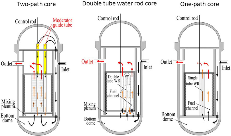
FIGURE 3. Three types of SCWR cores (Coolant flow schemes). Source: Oka 2014.
The two-path core adopts downward and upward coolant flow paths (Kamei 2006). The reactor coolant enters the RPV through the inlet nozzle. Some of the coolant flows into the top dome of the RPV and down through the fuel assemblies of the outer core. It mixes with the rest of the inlet coolant from the downcomer and flows up through the inner core fuel assemblies.
The double-tube water rod core adopts a reactor coolant flow path that first flows through the inner tube of the double-tube water rod and then downwards through the outer tube of the water rod (Section 2.1.1.1 of Oka 2014; Wu and Oka 2014a). It is mixed with the remainder of the inlet coolant from the bottom dome in the mixing plenum below the core. The upper core structure of the double tube water rod core is simplified by removing upper core moderator guide tubes from the two-path core. Small amount of the inlet coolant flows into the top dome of the RPV to keep its temperature low. It is the same way as a PWR.
In a single-path core, inlet coolant from the bottom dome flows into both single-tube water rods and fuel coolant channels (Section 2.1.1.3 of Oka 2014; Wu and Oka 2014b). The single tube water rod flow rate is kept low below pseudo critical temperature due to moderation. Small holes are provided on the top of the single tube water rod. Moderator is mixed with fuel rod coolant in the upper plenum above the core. The average outlet coolant temperature can be maintained at 500°C due to the low moderator flow rate. The mixing plenum below the double tube water rod core is not required for the one-path core.
Figure 4 shows the SCWR fuel assemblies of the one-path core. The SCWR fuel assembly is a square fuel assembly with many water rods. The walls of the water rods are provided with a thin layer of thermal insulation material from the fuel coolant channels. The water rods and coolant in the fuel channels are separated throughout the core. The fuel rod contains UO2 pellets inside a stainless-steel cladding tube. At SCWR coolant temperature, Zircaloy loses its strength and cannot be used. Fuel enrichment is varied to reduce axial, radial and local peak power. Gadolinia oxide is used as burnable poison to reduce power peaking. The fuel assembly is surrounded with a channel box, in other words, a wrapper tube to prevent cross flow between fuel assemblies. The fuel assemblies are fitted with nozzles with orifices at the bottom to adjust the coolant flow radially to match the core power. The peripheral fuel assembly is equipped with separation plates. Separation plate is for adjusting power to flow rate to achieve 500°C outlet coolant temperature. Refueling plans are run separately for peripheral core assemblies and inner core assemblies. Control rod guide tubes are provided in the inner core assemblies. SCWR control rods are similar to PWR control rods. The drive mechanisms are mounted on top of the RPV.
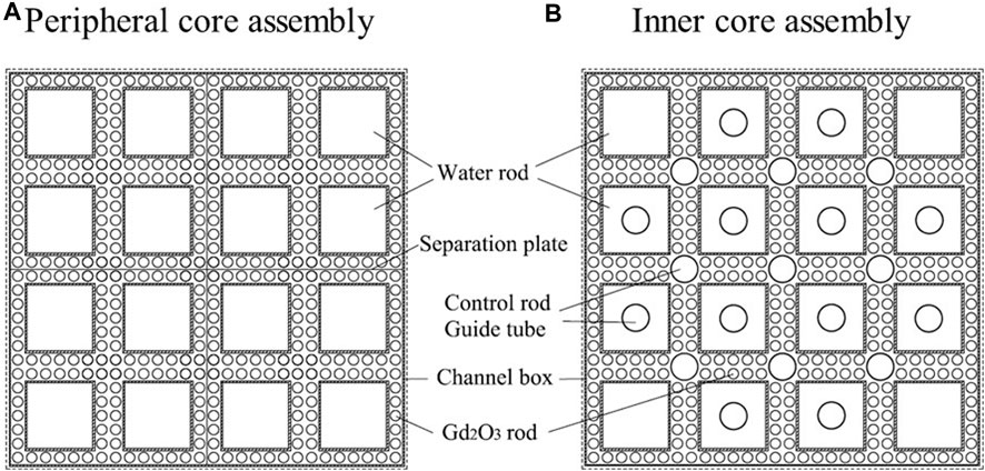
FIGURE 4. SCWR fuel assemblies (one-path core). Source: Wu and Oka 2014b.
Thermal design limit for LWRs is given to prevent boiling transition at abnormal transients. However, boiling phenomenon disappears at supercritical pressure. SCWR cladding temperatures are limited to maintain rod integrity at rated power and abnormal transients.
SCWR core design criteria at rated power are required to evaluate the availability of an outlet coolant temperature of 500°C at 25 MPa and an inlet coolant temperature of 280°C. They consist of thermal design criteria and neutronic criteria.
The thermal design criteria at rated power are:
1) Maximum linear heat generation rate (MLHGR) is less than 39 kW/m.
2) Maximum cladding surface temperature (MCST) is less than 650C for stainless steel cladding.
3) Moderator temperature in water rods is lower than the pseudo critical temperature at 25 MPa. It is 384°C.
The neutronic design criteria are:
1) Water density reactivity coefficient is positive. In other words, coolant void reactivity coefficient is negative during start-up and rated power.
2) Core shutdown margin is larger than 1.0% Δk/k.
Due to the higher coolant temperature of the SCWR, the MLHGR is lower than that of LWRs. The MCST is set for the core design at rated power. Fuel integrity is evaluated considering temperature rise from statistical thermal design, subchannel analysis, and abnormal transient analysis.
Three dimensional neutronic and thermal hydraulic (N-T) coupled core calculation were performed to estimate core characteristics. It is explained in Sections 2.3, 2.4 of the first book (Oka 2010). Figure 5 shows three-dimensional neutronic and thermal hydraulic coupled calculation models. Thermal hydraulic calculation is based on single channel model of a fuel rod and equivalent coolant channel surrounding the fuel rod as shown in Figure 5A. A single channel model of the water rod is used to estimate the moderator density within the water rod. It consists of a central circular moderator channel surrounded by water rod walls containing thermal insulation and an outer equivalent fuel coolant area. The three-dimensional core calculation model is shown in Figure 5B. A 1/4 symmetric quarter core is analyzed. It consists of homogenized fuel elements. The computer code system SRAC2002 developed by the Japan Atomic Energy Agency (JAEA) is used for neutronic calculations. The nuclear data library is JENDLE3.3. The three-dimensional core burnup calculations are performed using the COREBN code from SRAC 2002. COREBN is a multi-dimensional core burnup calculation code by finite-difference diffusion method based on macroscopic cross-sectional interpolation for each burnup. The macroscopic cross section sets required by the core burnup calculation are prepared by numerous cell burnup calculations and assembly burnup calculations. A set of macroscopic cross-sections required for core burnup calculations is created by a large number of cell burnup calculations and assembly burnup calculations. The macroscopic cross section sets of the fuel assemblies are allocated according to the cycle number of the fuel assemblies, insertion or withdrawal of the control rods, and coolant and moderator densities. The core is surrounded by a homogeneous layer of stainless steel and water that model the reflector. A macroscopic cross section sets is allocated for each fuel element volume and updated as the burnup proceeds. Each fuel element is further divided into calculation meshes to calculate neutron flux distributions. The three-dimensional core power distribution is obtained by evaluating the power density of each calculation mesh.
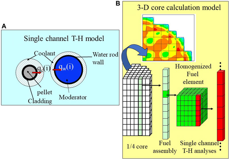
FIGURE 5. Three-dimensional Neutronic and thermal hydraulic Coupled Core Calculation models. Source: (A) Single channel T-H model, (B) 3-D core calculation model. Source: Oka 2011a.
To achieve an average reactor outlet coolant temperature of 500°C and MLHGR of less than 39 kW/m within the MCST limit of less than 650°C, the fuel assembly coolant flow distribution, fuel loading and reloading pattern, and control rod pattern are examined. Results for the two-path core are shown on slides 26, 27, and 28 of Oka 2011a for fuel loading and reloading pattern, control rod pattern, and core outlet coolant temperature, respectively. The change of MCST and MLHGR with cycle burnup for the two-path core is shown in slide 29 of Oka 2011a. It can be seen that the thermal design criteria are met. The neutronic criteria, negative coolant void reactivity from cold to operating condition and the shutdown margin were calculated and met for all cores. It is shown in slide 30 of Oka 2011a. A comparison of the core characteristics is summarized in Table 1. The characteristics of the double-tube water-rod core and the one-path core are the results before considering the control rod pattern. The thermal insulation materials of the water rods are ZrO2 for the two-path core and yttria stabilized zirconia (YSZ) for the double tube water rod core and the one-path core. The composition is 8YSZ-50% (8 mol% Y2O3/92 mol% ZrO2 sintered at 50% relative density). Yttrium has a thermal neutron capture cross section of 1.284 b, while zirconium has a thermal neutron capture cross section of 0.1957 b. This is thought to be the reason why the double-tube water rod core and the one-path core have high enrichments. ZrO2 is considered to be suitable as a thermal insulator for water rods due to its low neutron absorption and experience in nuclear reactor applications.
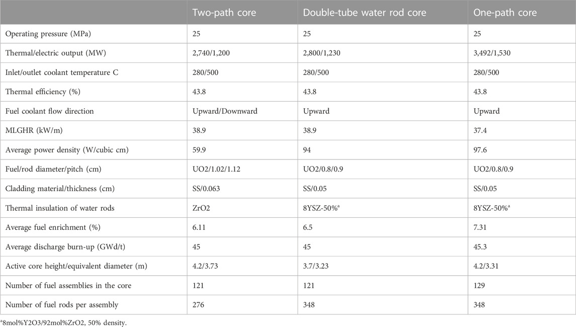
TABLE 1. Characteristics of SCWR cores.
The effect of heat transfer correlations on MCST is described in Table 4 of Kamei 2006. Watts correlation gave highest MCST. Watts correlation has been used for the core design and subchannel analysis since the study of Kamei 2006. The results in Table 1 are obtained using the Watts correlation. A comparison with experiments reports that the Watt correlation provides the best predictive performance (page 256 of Oka 2014).
Assessing integrity requires assessing the nominal peak cladding temperature of the fuel rods in the fuel assembly at rated power conditions. For this purpose, the subchannel analysis code was developed. A 3D core calculation provides the core power distribution using a homogenized model of the fuel assemblies. The power distribution of fuel rods (pins) must be reconstructed from core calculations. The relative pin power distribution is calculated by the SRAC’s Assembly Burnup Module (ASMBURN). The result is used for subchannel analysis. The macroscopic cross section for ASMBURN were prepared as a function of burnup history, coolant density and control rod insertion. A sub-channel analysis of the fuel assembly is performed using the pin power distribution to obtain the coolant density distribution of the fuel assembly. Assembly burnup calculation and the subchannel calculation are iterated until relative pin power distributions and coolant density distributions converge. A reconstruction of the pin power distribution is shown on slide 35 of Oka2011a. The results of the subchannel analysis give the MCST in the fuel rods at nominal power. The results are presented in slide 36 of Oka2011a and Section 2.5 of Oka 2010. It should be noted that although the water rod walls are provided with insulation, heat transfer occurs between the fuel channels and the water rods.
SCWR core thermal performance involves various engineering uncertainties. Uncertainties arise from calculations, measurements, instrumentation, manufacturing, fabrication and data processing. A statistical method has been developed to evaluate and combine the uncertainties in the thermal design. This method is referred as the Monte Carlo statistical thermal design procedure for SCWR. The engineering uncertainties are considered with respect to 95/95 limit. The procedure and the results are described in Yang 2006, Section 2.6 of Oka 2010 and slides from 39 to 41 of Oka 2011a. The standard deviation of system parameter uncertainty is 18.32°C and standard deviation of correlation uncertainty is 6.33°C. The engineering uncertainty of 95/95 confidence is 31.88°C, about 32°C for the two-path core. The sub-channel analysis yields an increase of 58°C from the limit of 650°C for 3D core calculations when using homogenized fuel assemblies. The statistical thermal design gives 32°C increase. Adding 90°C to 650°C gives maximum peak cladding surface temperature of 740°C. It is the highest MCST at steady sate condition. The relation between the peak cladding temperatures is shown in Figure 6 and slide 42 of Oka 2011a. Fuel integrity is assessed by temperature rise from 740C at abnormal transients and accidents by safety analysis, as shown in Figure 2.85 of Oka2010 and Figure 3 of Yang 2006.
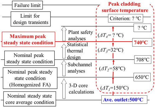
FIGURE 6. Peak cladding surface temperatures. Source: Oka 2011a.
FEMAXI-6 code of JAERI was used for fuel rod analysis for design and to develop the criteria of its integrity at normal operation and abnormal transients. The code considers a single fuel rod and surrounding coolant in an axis-symmetric cylindrical geometry. It is capable of coupled solution of thermal analysis and mechanical analysis, enabling accurate prediction of pellet gap size and pellet-clad mechanical interaction (PCMI) in high burnup fuel rods at normal operation and transient conditions.
The linear heat generation rate affects the fuel centerline temperature strongly. The average linear heat generation rate and average coolant core outlet temperature are assumed to be 170W/cm and 500°C respectively. The maximum cladding surface temperature of the fuel rod is assumed to be 740°C from the beginning of life (BOL) and the end of life (EOL) of the fuel rod. For the core average discharge burnup of 45GWd/t, the fuel rod subject to the analysis is assumed to have a burnup of 62.8GWd/t (fuel rod average) with peak pellet burnup of 71.7GWd/t. Basic fuel rod behaviors are analyzed by FEMAXI-6 code for the fuel rod deign.
In designing the fuel rods for the SCWR, the initial internal pressurization of the fuel rod, the release of fission product (FP) gases, and the PCMI behavior of the fuel rod are important factors. FP gas release is closely related to the PCMI behavior. The initial pellet grain size has the effect of causing a higher PCMI pressure at the EOL. Increasing the initial pellet-cladding gap size can reduce the PCMI pressure, but it has the effect of increasing the pellet temperature, which also leads to a higher gas release rate. Thus, generally designing efforts in reducing the FP gas release and PCMI are in a tradeoff. That, in turn, implies that the deigning efforts in reducing the compressible stress on the cladding at the BOL and tensile stress at the EOL are also in a tradeoff.
Eight fuel rods are designed under different conditions. Among eight fuel rods, four fuel rods are designed with the constraint is kept below the coolant pressure of 25 MPa throughout their life times and other four rods are designed without the constraint of the internal pressure. For both cases, fuel rods are designed with different gas plenum lengths of 10% or 50% plenum/fuel volume ratio and gas plenum positions, either top or bottom of the fuel rod. The results are seen in Table 2.22 of Oka 2010. One of the fuel rod designs is summarized and compared with those of typical BWR and PWR in Table 2.23 of Oka 2010. This design is the case of no constraints of the internal pressure, lower gas plenum position and 10% plenum/fuel volume ratio. In the case of this design the cladding material needs to withstand the stress −64 to +71 MPa at the cladding centerline temperature of 757°C for a period of 36,000–48000 h (500 days multiplied three to four cycles). Some advanced austenitic stainless steels, such as PNC1520 of the former Japan Nuclear Cycle Development Institute (JNC) may be able to meet the requirement. The properties and the cladding material development based on PCN 1520 is described in chapter 4 of Oka 2014.
Abnormal transient criteria (transient criteria) are very important to ensure fuel integrity. These limit the maximum allowable coolant temperature and choice of the fuel cladding material used at high temperature. The FEMAXI-6 code is used to develop transient criteria using the same computational models as the fuel rod design.
Abnormal transients are defined as events that will lead to the situation in which the nuclear plant maintain the normal operation due to an external disturbing factor that may occur during the life span of nuclear plant under the operational conditions including single failure or malfunction of devices or single operational errors by operators, and to the abnormal situation in which the nuclear plant is not planned to operate and that may occur with the same probability as the former. A set of abnormal transients and accidents as standard safety analysis of the current LWRs is studied for the SCWR. It is described in chapter 8 of this review.
The requirements for ensuring the integrity at abnormal transients are the same as those of LWRs:
1) No systematic fuel rod damage
2) No fuel pellet damage
3) No reactor pressure vessel (RPV) damage
The above three requirements are not directly related to the parameters that can be easily obtained in the safety analysis. The following four principles are adopted to derive rationalized new criteria for abnormal transients.
1) The fuel rod buckling collapse should not occur when the fuel rod cooling is deteriorated.
2) The fuel rod mechanical failure should not occur.
3) The fuel enthalpy should be below the limit.
4) The primary coolant pressure boundary should not fail.
The above principles can be rewritten quantitatively as in the case for LWRs. For example, the same or similar values that have been used for LWRs may be directly adopted as follows.
1) The pressure difference on the cladding should be less than 1/3 of the collapse pressure of the cladding
2) The strain level on the cladding should not exceed the elastic limit (i.e., no plastic strain on the cladding).
3) The fuel pellet centerline temperature should be less than its melting point.
4) The system pressure should not exceed 28.9 MPa (105% of the maximum pressure for normal operation).
5) The internal pressure of the fuel rod should not become excessively high (less than the coolant pressure during normal operation).
By using the fuel analysis code, the allowable maximum cladding temperature and power for maintaining the fuel integrity are determined. The allowable maximum cladding temperature for abnormal transients is 850C. The allowable maximum power is derived in relation with power rise rate. The allowable maximum power is 182% for power rise rate over 10%/s, 136% between 0.1% and 10% power rise rate and 124% between 0.1% and 1% power rise rate (Table 2.24 of Oka 2010). Development of transient criteria is described in Section 2.8 of Oka 2010. The principle for preventing cladding failure is seen in slide 32 of Oka 2011a. The criterion of abnormal transients for LWRs is no boiling transition. That for the SCWR is “no plastic strain and no buckling collapse” of the fuel cladding. Thus, cladding temperature is limited below 850C.
Figure 7 shows the SCWR main plant system. It is a two-loop system. Supercritical steam flows into the turbine from the outlet nozzles of the reactor pressure vessel (RPV) through the main steam lines. Water is pumped from the condenser by a series of pumps and returned to the RPV through the inlet nozzle. A series of low pressure (LP) and high pressure (HP) feedwater heaters are installed upstream and downstream, respectively, of the main feed water pump (reactor coolant pump) to preheat the cold water before it enters the reactor. Although not shown in the figure, a condensate purifier is installed after the condenser as a supercritical fossil-fired power plant. Whole SCWR coolant is purified after condensation. This is the advantage of the SCWR over LWRs in managing material corrosion such as SCC. In LWRs, the high temperature recirculating reactor coolant cannot be completely purified.
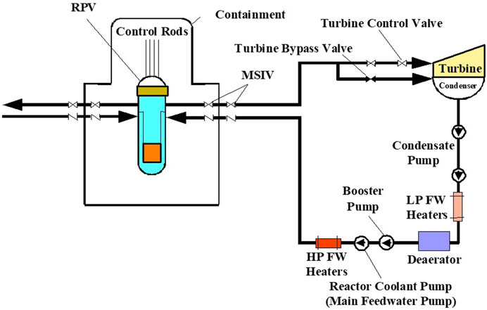
FIGURE 7. SCWR main plant system. Source: Oka 2011b.
A containment vessel (CV) surrounds the RPV and control rods. A SCWR CV can be either a suppression pool type like BWRs or a dry type like PWRs. The volume of the CV is smaller than that of a LWR due to the low coolant inventory in the CV. For CV, the dry type is simpler and better than the suppression pool type. The CV is equipped with main steam isolation valves (MSIVs) for accident isolation. The turbine control valve is installed to regulate steam flow to the turbines. The turbine bypass valve is installed to vent steam to the condenser during turbine load rejection. The SCWR plant system and main components are described in chapter 3 of Oka 2010. It includes heat balance and thermal efficiency calculations.
Plant dynamics calculation code, SPRAT was developed for conceptual design and analysis of plant control and plant start-up. It consists of single channel heat transfer model for a fuel and a water rod, a node junction model for the plant system, and plant dynamics model. SPRAT mainly calculates mass and energy conservations, fuel rod heat transfer and point kinetics. The calculations use models of neutron kinetics, fuel rod heat transfer, fuel channel thermal-hydraulics and ex-core circulation. The neutron kinetics model is a point kinetics model with six delayed neutron precursor groups. Doppler and density feedback is considered. Fuel rod heat transfer model considers only radial heat transfer. Thermal conductivity of fuel pellet is that of the LWR fuel pellet. The thermal hydraulic model of fuel channel is single channel single-phase one-dimensional model consisting of mass conservation, energy conservation, momentum conservation and state equations. Forward finite difference method is used for axial nodes. The ex-core circulation models include orifice model, feedwater pump model, feedwater pipe model and exit valve model. The calculation models, flow-chart and equations are described in Section 4.2 of Oka 2010 and slides 5–19 of Oka 2011b.
Due to the word limit of the review, descriptions of plant control, plant startup and stability are short. Please see the slides of Oka 2011b and the descriptions in chapter 4 and 5 in Oka 2010.
Plant control systems are designed using plant dynamics code. The steps and the results are as follows:
1) Find sensitivity of the control parameters: The sensitivity to the perturbations is described in slides 24 to 27 of Oka 2011b.
2) Design control system: From the results of the sensitivity studies, reactor power is controlled by the control rods, pressure is controlled by turbine control valve. Steam temperature is controlled by the main coolant pump. The plant control system is shown in slide 23 to 31 of Oka 2011b.
3) Assess stable response against perturbations: Plant dynamics with control system are calculated. The stable responses are on slides 32–36 of Oka 2011b.
The control strategies of LWRs are “turbine-following reactor” for BWR and ”reactor-following turbine” for PWR. SCWR is “turbine-following reactor” like BWR. Fossil-fired power plants employ “turbine-boiler coordination” control. The strategy is presented on side 37 of Oka 2011b.
Both the constant pressure startup system and sliding pressure startup system of the SCWR are studied with reference to those of FPP. A constant pressure startup is to start the nuclear heating at supercritical pressure and keep the pressure constant during the power increase.
The SCWR constant pressure start-up system is shown in Figure 5.3 of Oka 2010. It is compared with that of FPP on slide 41 of Oka 2011b. The analysis is described in Section 5.2.2 of Oka 2010.
Sliding pressure startup means start heating at subcritical pressure. The sliding pressure FPP is equipped with a steam water separator, a separator drain tank, drain valves and recirculation pumps in the main steam line in the furnace as seen in Figure 8A. It is, however, not good to install a water separator in the reactor pressure vessel of the SCWR. The water separator is equipped in the bypass of the main steam line of the SCWR. Instead of the recirculation pumps, the drain of the water separator is sent to the condenser directly or via additional heaters of the reactor inlet coolant line. The sliding pressure startup system of the SCWR is shown in Figure 8B. The dimensions and weights of the flash tank and water separators are compared in Tables 5.2, 5.4 of Oka 2010 respectively. Providing a water separator with the bypass line and an additional heater makes the lightest of the options.
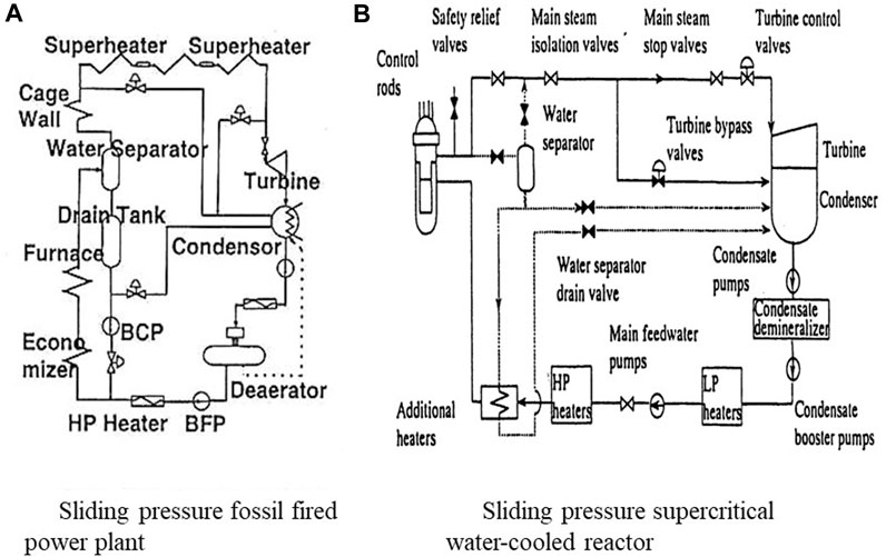
FIGURE 8. Sliding pressure startup systems:(A) Sliding pressure fossil fired power plant, (B) Sliding pressure supercritical water-cooled reactor. Source: Oka 2011b.
The startup thermal analysis code was prepared by modifying the plant dynamics code, SPRAT. The transition from nucleate boiling to film boiling inevitably occurs at the sliding pressure startup. The heat transfer correlations used for the calculation are given in Section 5.3.1.1 of Oka 2010.
Both thermal criteria and mechanical stress criteria must be met during the startup. The mechanical stress criterion is that the thermal stress of the RPV should not be excessive. For example, for a BWR, the reactor pressure vessel coolant temperature rise should be less than 55°C/h.
The thermal criteria for plant startup of SCWR are:
1) The MCST must not exceed the rated limit.
2) The moisture content in the turbine inlet steam must be less than 0.1%.
3) The enthalpy of the core outlet coolant must be high enough to provide the required turbine inlet steam quality.
4) Boiling should be prevented in the water rods.
We assume that MCST occurs in the channel with the maximum linear heat generation rate of 39 kW/m. We analyze the maximum power channel to calculate the MCST and determine if it meets the criteria.
In the pressurization phase, the maximum allowable and minimum power requirements are calculated by varying the flow rate and feedwater (inlet coolant) temperature. Maximum allowable power is limited by criteria 1 and 4, MCST limits, and water rod density. The minimum required power comes from the 2 and 3 criteria, low water content and high steam quality. A range of operable power and pressure is obtained between the maximum allowable power and the minimum required power. At pressures between 20 and 22.1 MPa, the transition to film boiling and the critical heat flux limit reduce the operable region. The results are presented in Section 5.3.3 of Oka 2010 and slides 48 of Oka 2011b. Critical heat flux may be increased by fuel rod spacers, but the effect is not included in the calculation. The sliding pressure startup curve which is obtained from the thermal criteria is shown in Figure 9A.
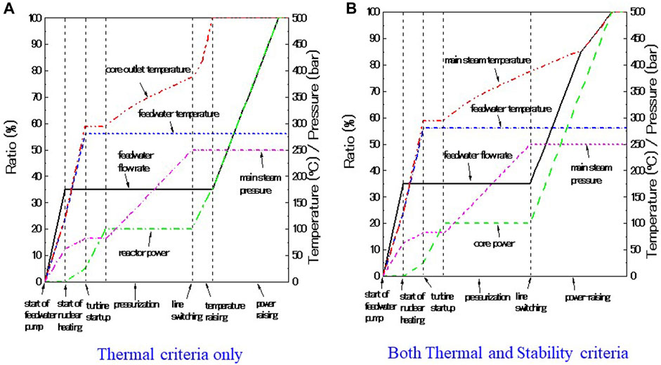
FIGURE 9. Sliding pressure startup curve: (A)Thermal criteria only, (B) Both Thermal and Stability criteria. Source: Oka 2011b.
As can be seen in Figure 1C, the coolant density in SCWRs changes dramatically around the pseudo-critical temperature. At 7 MPa, the BWR condition, the change is discontinuous and greater than the supercritical pressure. Frequency domain linear stability analysis is used for SCWR stability analysis. This is the same method used for BWR stability analysis. Both thermal hydraulic stability and coupled neutronic and thermal hydraulic stability are analyzed. The governing equations for the thermal hydraulic stability analysis are given in Section 5.4.3.1 of Oka 2010. The governing equations for the coupled thermal-hydraulic stability analysis are given in Section 5.5.2 of Oka 2010.
The frequency domain linear stability analysis procedure is as follows (slide 54–56 of Oka 2011b):
1) Write governing equations.
2) Linearize governing equations by perturbation.
3) Perform Laplace transform.
4) Obtain overall system transfer functions from open loop transfer functions.
5) Determine the roots of characteristics equation: 1 + G(s)H(s) = 0
6) Calculate decay ratio from the dominant pole.
Decay ratio (DR) is defined as the ratio of two consecutive maxima of the impulse response.
Stability criteria are the same as BWR criteria:
Thermal hydraulic stability: DR
Coupled neutronic thermal hydraulic stability: DR
Thermal hydraulic stability is analyzed at full power normal operation, partial power operation at 25 MPa and pressurization phase. The effects of orifice pressure drop, core power, feedwater flow rate, pressure, core inlet temperature and water rod mass flow rate on the stability are studied. Mechanisms, analysis methods and results are described in Section 5.4 of Oka 2010 and slides 65–72 of Oka 2011b.
Coupled neutronic thermal hydraulic stability during full power operation, partial power operation at 25 MPa and pressurization phase is analyzed. The same effects as the thermal hydraulic stability on the coupled stability are studied. These are described in Section 5.5 of Oka 2010 and slides 73 to 90 of Oka2011b. As shown in slides 84 and 85 of Oka 2011b and figure 5.63 of Oka 2010, it can be seen that a higher flow rate is required to meet the coupled stability criterion during power raising phase. The sliding pressure startup curve that satisfies both thermal and stability criteria is shown in Figure 9B (Tin et al., 2005). It is described in Section 5.6 of Oka 2010.
The analysis results show that the SCWR maintains both thermal-hydraulic and coupled stability during normal operation and power raising phases despite low coolant flow rate and large density change in the core. A start-up curve is derived that meets both thermal and stability criteria.
The SCWR safety principle is to keep core coolant flow rate, not coolant inventory. This is the same principle as other single phase coolant reactors such as a LMR (liquid metal cooled reactor) and a GCR (gas cooled reactor). The safety principle of LWRs is to maintain coolant inventory. However, monitoring coolant flow rate is more reliable than monitoring coolant inventory from water level at depressurization. A comparison of these safety principles is shown in slide 51 of Oka 2011a and Table 6.1 of Oka 2010.
Figure 10 shows the SCWR plant and safety system. The reactor shut down systems are the control rods and standby liquid control system (SLCS). The SCWR control rod drives are mounted on the top of the RPV as a PWR. The SLCS contains borated water, which is injected to RPV through the low-pressure core injection system (LPCI) piping. The SCWR has two main coolant lines. It is equipped with two turbine-driven Reactor Coolant Pumps (RCPs) for normal operation. Two motor-driven RCPs with half the capacity of the turbine-driven RCPs, similar to the BWR, are installed for plant startup and backup of the turbine-driven RCPs. The containment vessel is either a large dry type as a PWR or the suppression pool type as a BWR which is shown in figure. A pressure suppression pool or large water pool is installed in the CV for pressure suppression and emergency coolant supply.
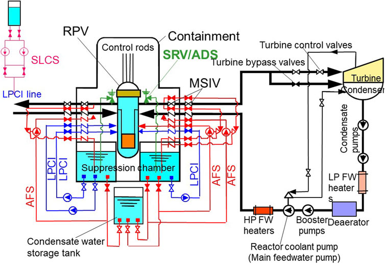
FIGURE 10. SCWR Plant and safety system. Source: Oka 2011a.
Three auxiliary feed water systems (AFSs) are provided to backup these RCPs. Single train capacity is 4% of rated flow at 25 MPa. AFS also serves as reactor core isolation cooling (RCIC). Three trains of LPCI are provided for AFS backup and loss of coolant accident (LOCA) mitigation. LPCI has the function of residual heat removal system (RHR). Single train capacity is 25% of the rated flow at 1 MPa. Emergency diesel generators supply electric power to the LPCI even if offsite power is lost. In this case, the starting time of the emergency diesel generator is assumed to be 30 s. Eight units of Safety Relief Valves (SRVs) are provided in case the turbine trips without bypass or main steam isolation valves (MSIVs) closed for coolant discharge. The SRV also have the function of acting as the automatic depressurization system (ADS), similar to the BWRs. The actuation condition of the safety system is seen in slide 53 of Oka 2011a and Table 6.2 of Oka 2010. The capacities and configurations of the safety system are described in slide 56 of Oka 2011a and described in Section 6.3 of Oka 2010.
Table 2 shows the actuation conditions of the safety system. Coolant supply abnormalities from the cold leg are detected as “low flow rate”, and coolant discharge abnormalities from the hot leg are detected as “high pressure”. When the decay heat cannot be removed at supercritical pressure, which corresponds to a low level 3 flow rate, the reactor is depressurized and then cooled by the LPCI. When the pressure decreases from the supercritical to subcritical region, boiling transition will occur on the fuel rod surface, leading to rapid increase in the cladding temperature. It is known that minimum heat transfer coefficient is especially small just below the critical pressure. Therefore, the pressure should not stay at or decrease slowly around critical pressure. So, the reactor is depressurized at a low level 2 pressure, which is 106% of the critical pressure. The actuation conditions of the safety system are described in Section 6.3.2 of Oka 2010.
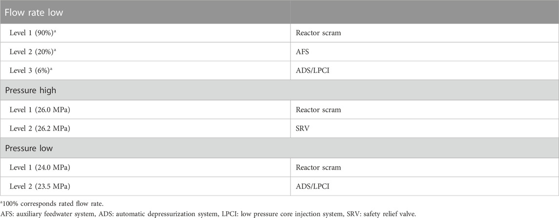
TABLE 2. Abnormal levels and actuations (Source: Oka, 2011a).
The abnormal events of the SCWR are derived by referring to those of LWRs, LMRs and GCRs. They are compared with those of LWRs in Table 6.4 of Oka 2010. There are several types of abnormality. The abnormal events related to ”decrease in core coolant flow rate” are the most important for SCWR, because keeping core cooling is the fundamental safety requirement. The “loss of all feedwater flow” of LWRs is classified as an abnormal transient. In PWR, it occurs in the secondary system, and there is a large water inventory in the steam generators. BWRs have recirculation system, and there is a large water inventory in the RPV. Therefore the “total loss of feedwater” does not immediately lead to a loss of flow in the core. The “total loss of reactor coolant flow” of LWRs corresponds a trip of all the primary coolant pumps of PWRs and a trip of all the recirculation pumps of BWRs. It is classified as an accident.
The feedwater pump of SCWR is the same as the reactor coolant pump. The “loss of all feedwater flow” and the “total loss of reactor coolant flow” are the same incidents. Classification of this event depends on the frequency. Also, the guidelines for Japanese LWRs are followed. A simultaneous sudden trip of all pumps that have been directly maintaining the core coolant flow rate must be classified as a “total loss of reactor coolant flow” accident. These pumps correspond to the primary pumps of PWRs and recirculation pumps of BWRs. Since the RCPs of the SCWR also maintain the core coolant flow rate, a simultaneous sudden trip of the RCPs is classified as the “total loss of reactor coolant flow” accident, assuming that its frequency will be less than 10−3 per year by system separation and high reliability. The selection and classification of abnormal events is described in Section 6.4 of Oka 2010. The initiating events for safety analysis of SCWR is summarized in Table 3.
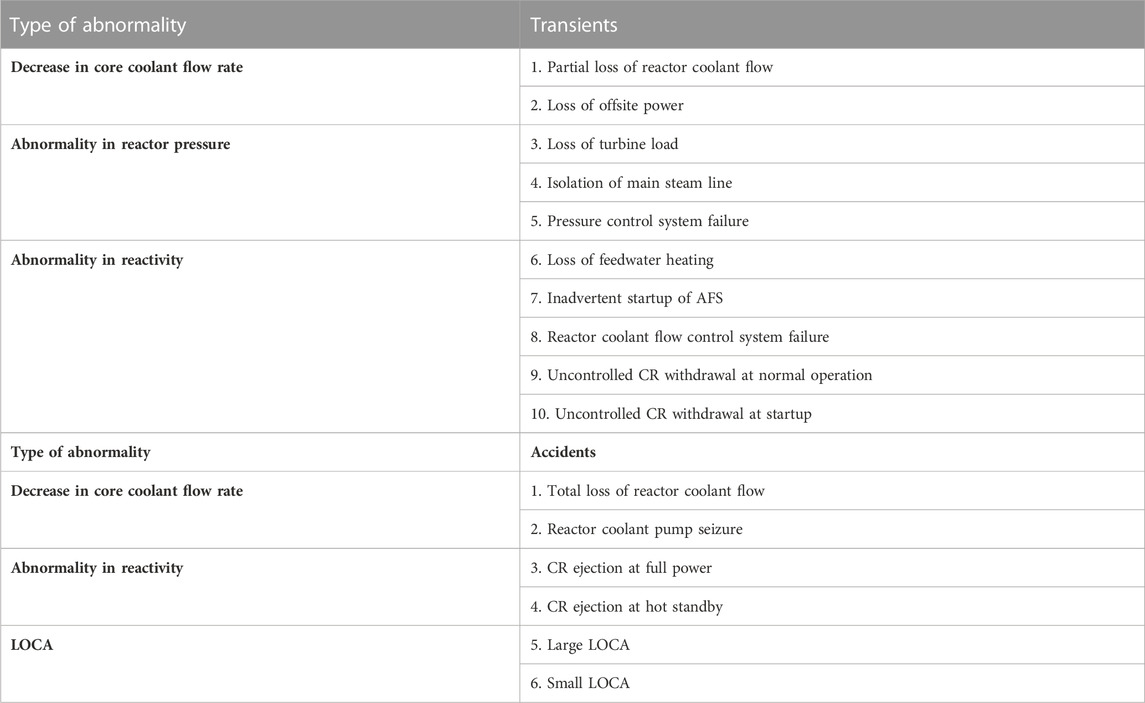
TABLE 3. Initiating events for safety analyses (Source: Oka, 2011a).
Safety criteria are necessary for safety evaluation. The requirements for abnormal transients are the same as those for LWRs: no systematic fuel rod damage. The requirements for accidents are no excessive core damage and no pressure boundary damage, which is the same as for LWRs. Safety criteria are determined for concept development. Because heat transfer deterioration is a much milder phenomenon than boiling transition, heat flux criterion such as minimum deterioration heat flux ratio is removed from the transient criterion.
The types of abnormalities are separated into “loss of cooling” and “overpower”. For the “loss of cooling” type transients, the limiting failure mode is expected to be the buckling collapse of the cladding due to the decrease in the Yang’s modulus at the elevated temperature. The maximum allowable temperature of the cladding at abnormal transients is determined as 850°C as described in Section 2.5 of this review, taking several conservatisms, so that the pressure difference on the cladding is less than one-third of the collapse pressure.
For “loss of cooling” type accidents, the requirement is to maintain a coolable geometry, as in LWRs. The limiting failure mode is expected to be oxidation of the cladding. The criterion of the cladding temperature is set at 1260°C for stainless steels, taken from the criterion for LOCA of early US PWRs with stainless steel cladding (NUREG 0065).
For the “overpower” type transients, the limiting failure mode is expected to be burst or PCMI. The maximum allowable power is determined through the fuel rod thermal and mechanical analyses. For abnormal transients, the criteria are that the allowable maximum power is 182% of rated power for power rise rate over 10%/s, 136% between 0.1% and 10% power rise rate and 124% between 0.1% and 1% power rise rate as shown in Table 2.24 of Oka 2010. For “overpower” type accidents, such as control rods ejections, the maximum allowable fuel enthalpy is determined 230 cal/g, the same as in LWRs. A transient with reactivity insertion over 1$ is not expected in the SCWR because the reactor is tripped before a CR cluster is fully withdrawn.
The principle of safety criteria for fuel rod integrity is seen in Table 6.6 of Oka 2010 and slide 57 of Oka 2011a. The initial condition (temperature) and criteria of MCST for safety analysis is shown in slide 58 of Oka 2011a. The margins of the temperature criteria of 850°C and 1260°C from the peak MCST at steady state condition (740°C) are 110°C for abnormal transients and 520°C for accidents.
The relative pressure change in SCWR is smaller than that in LWRs due to the once-through coolant cycle and high operating pressure. The maximum allowable pressures for abnormal transients and accidents are set 105% and 110% of the maximum pressure of the normal operation (27.5 MPa). The criteria are 28.9 MPa for abnormal transients and 30.25 MPa for accidents.
An anticipated transient without scram (ATWS) is defined as an abnormal transient followed by failure of a reactor scram. Since SCWR is a simplified LWR, the probability of an ATWS is expected to be on the same order as that of LWRs. An ATWS of the SCWR is classified as “beyond design basis event” (BDBE). A deterministic evaluation of an ATWS is a global requirement because it is a potential safety issue that may lead to core damage under postulated conditions. Also, it is expected that inherent safety characteristics of nuclear reactors, not only reactivity feedback but also reactor system dynamics, can be clearly identified at ATWS conditions due to scram failure. Therefore, deterministic ATWS analysis is carried out for the SCWR as well as the abnormal transients and accidents. Despite the significantly low probability of an ATWS compared to other accidents, the same criteria as those of accidents are applied. The safety criteria are described in Section 6.5 of Oka 2010.
The plant dynamics calculation code, SPRAT is extended for the analysis of abnormal transients and accidents of the SCWR. A hot channel, where linear heat generation rate and maximum cladding surface temperature are the highest in the core is modeled as well as the average channel in order to calculate the highest values of cladding temperature and pellet enthalpy. The model is seen in slide 60 of Oka 2011a and Figure 6.12 of Oka 2010. For reflooding analysis of LOCA, SCRELA reflood module is used. SCRELA was developed for LOCA analysis of the SCWR in 1990s. The safety analysis method is described in Section 6.6 of Oka 2010.
Figure 11 summarized the safety analysis results of the two-path core. The event number corresponds to those of Table 3. Both begging-of-equilibrium-cycle (BOEC) and end-of-equilibrium-cycle (EOEC) are analyzed. For each event, the figure shows the results when either BOEC or EOEC has a smaller margin to the criteria. All the results satisfy the criteria with fair margins. A small LOCA shows the highest temperature of all accidents, with a margin of 200°C. The results are described in Section 6.7 of Oka 2010. The SCWR has the following excellent safety characteristics.
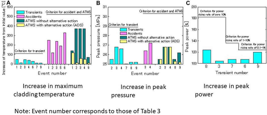
FIGURE 11. Summary of safety analysis results: (A) Increase in maximum cladding temperature, (B) Increase in peak pressure, (C) Increase in peak power. Source: Oka 2011a.
ADS activation or LOCA depressurization induces SCWR core coolant flow because of the once through coolant cycle. A large water inventory in the water rod and upper dome of the RPV acts as an in-vessel accumulator. Reactor power decreases due to negative coolant void reactivity characteristics. It is seen slide 61 of Oka 2011a.
The SCWR core has many water rods for moderation. Heat transfer to water rods increases as loss-of-flow occurs. The water rods act as “heat sink”. Water rods also supply water to the fuel channels and act as “water sources” except for the one-path core. It is described in slide 62 of Oka 2011a.
The results of the analysis of the ATWS events without alternative actions are presented in slide 63 of Oka 2011a. The results show that the criteria are met without any alternative actions. The reason for the mild behavior is the small power increase by valve closure due to no void collapse. Density increase is suppressed by flow stagnation. Due to density feedback, reactor power decreases with core flow.
A safety analysis of the double-tube water rod core is provided in Section 2.1.2.3 of Oka 2014. A one-pass core safety analysis is provided in Sections 2.1.2.4, 2.1.2.5 of Oka 2014. The peak MCST of the one-path core is higher, because the water rods do not supply coolant to the fuel channel. All criteria are satisfied.
The safety analysis uses a single-channel code under the assumption that the relative mass flux distribution in the fuel assembly under abnormal conditions is the same as that under steady conditions. There is a concern that the distribution may change at abnormal conditions, especially flow decreasing events. A transient subchannel analysis code is developed using Simplified Marker and Cell (SMAC) method. It is described in Section 6.8 of Oka 2010. The calculated results of the flow decreasing events shows that increase in MCST is 25°C higher for the abnormal transient and 140°C higher for the accident, but the SCWR still has a margin to each criterion.
Concepts for a fast reactor version of SCWR are developed at the University of Tokyo and Waseda University. It was called SCFBR, SCFBR-H, SWFR, SCFR, Super FR, etc. In this review, we will call it SCWR-F. The research program was funded by MEXT (Ministry of Education, Culture, Sports, Science and Technology) between 2005 and 2014. It was a huge budget. The author was the leader of the program. About two-thirds of the budget were spent on experiments. Experimental results are commonly useful for both SCWR and SCWR-F.
The SCWR-F fuel is plutonium-uranium mixed oxides (MOX). The plant system is the once-through coolant cycle, similar to the SCWR shown in Figure 7. The core consists of tight lattice fuel assemblies without water rods. This allows SCWR-F achieve higher power density than SCWR. Despites its advantage, SCWR-F requires reprocessing of spent fuel to obtain plutonium for fuel. The low reactor coolant flow rate characteristics due to the high enthalpy rise of the once-through coolant cycle match well with the SCWR-F’s tight fuel lattice characteristics in managing high pump power requirements and instabilities.
Figure 12 shows an example of fuel assemblies and their arrangement in the core. The fuel rods are arranged in tight lattice of the fuel assembly. The core consists of seed fuel assemblies and blanket fuel assemblies (FAs). These are hexagonal and have a channel box (wrapper tube). Control rods are inserted into seed fuel assemblies. SCWR-F should have negative coolant void reactivity characteristics. For this purpose, the concept of zirconium hydride layer was invented. The blanket fuel assembly has a thin (approximately 1 cm thick) zirconium hydride layer inside. Fast neutrons produced in the seed fuel assemblies during coolant voiding are moderated by the layer and absorbed by the blanket fuel rods inside it. This makes coolant void reactivity negative when coolant density decreases. The effect of zirconium hydride layer on void reactivity is discussed in Section 7.3.1 of Oka 2010. Seed and blanket fuel assemblies are placed in the core to flatten the power distribution and make the reactivity of coolant void negative.
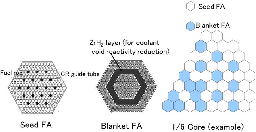
FIGURE 12. SCWR-F fuel assemblies and core layout. Source: Oka 2011a.
A two-path core coolant flow scheme is shown in Figure 7.35 of Oka, 2010 and slide 82 of Oka 2011a. Both seed and blanket fuel assemblies in the peripheral core are cooled by downward flow through the upper dome of the RPV. This is mixed with the remaining coolant from the downcomer in the mixing plenum below the core. This raises average outlet coolant temperature to over 500°C. The coolant flow scheme is similar to the SCWR two-path core shown in Figure 3. The reactor characteristics is seen Table 7.15 of Oka 2010. The increase in MCST is evaluated by subchannel analysis and statistical thermal design. Plant control, stability and safety analysis for SCWR-F are performed in the same way as for the SCWR. The results of the safety analysis are presented in slide 85 of Oka 2011a. SCWR-F meets safety criteria, but safety analysis results are more stringent than the SCWR. The reason for this is the high power density and the absence of water rods to supply coolant and absorb heat in the event of abnormal events. Small break LOCA and loss of flow type ATWS events require depressurization to avoid strong mismatches between power and flow. The design and analysis of the two-path core SCWR-F is described in chapter 7 of Oka 2010.
The coolant flow scheme is improved in later SCWR-F designs. These are two-path core with all upward flow cooling and one-path core with all upward flow cooling. It can be seen in Figure 2.54 of Oka 2014. The one-path core uses blanket fuel assemblies with MOX fuel pellets at the bottom. It reduces power swing (power increase with burnup) of the blanket fuel assemblies and increases outlet coolant temperature. The refueling scheme and the structures of the inlet and outlet plenum are simplified. The core designs are described in Section 2.2.1.3, 2.2.1.4 of Oka 2014 respectively. The results of safety analysis are found in Section 2.2.3.3, 2.2.3.4 of Oka 2014. The results of transient subchannel analysis are seen in Figure 2.194 of Oka 2014. All safety criteria are satisfied.
The fuel rod spacing of the SCWR and SCWR-F is small, for example, 1 mm. Innovative grid spacer concept for the reactors, which is called triangular prism type grid spacer is developed by using CFD code, STAR CCM+6.04. It decreases MCST by 18°C. The result is described in Section 2.4 of Oka 2014.
Breeding of SCWR-F has been studied. The highest fissile plutonium surviving ratio is 1.026. It is the two-path core, not one-path core. High breeding is not possible, because SCWR-F is light water cooled. Accurate estimation of the breeding ratio requires increasing the number of neutron energy groups in the cross-sectional library near the eV region. The reason is that neutron spectrum is softer than that of liquid metal cooled fast reactors. The result of the analysis is described in Section 2.7.2 of Oka 2014.
Heat transfer and fluid flow experiments were conducted at Kyusyu University using a surrogate fluid, Chlorodifluoromethane, HCFC22. A new heat transfer loop was built on the SCWR-F budget. The experiment includes heat transfer and pressure drop measurements in single tube, single rod, 3 and 7 rod bundle geometries. We studied the effect of grid spacer on heat transfer, critical heat flux at near critical pressure, condensation, critical-flow and cross-flow between bundle channels. The results are described in Section 3.1 of Oka 2014. The results of 7 rod bundle experiment are seen slide 89 of Oka 2011b. Heat transfer experiments in a single tube geometry using supercritical water were conducted at JAEA Naka Laboratory to validate the data for the surrogate fluids. The results are found in Section 3.2 of Oka 2014. Computational fluid dynamics (CFD) analysis of experiments was conducted at JAEA Tokai laboratory. It is described in Section 3.3 of Oka 2014.
Zr- modified 15Cr20 Ni austenitic alloy (1520Zr alloy) was developed for fuel cladding of the SCWR and SCWR-F at Tohoku University. The austenitic alloy PNC1520 had been developed by PNC (now JAEA) for Japanese liquid metal fast breeder reactor program. The required high temperature strength and compatibility with high temperature water environments was improved. 1520Zr alloy was confirmed to have excellent creep strength. The oxidation properties in supercritical water and SCC susceptibility in supercritical water of 15Cr20Ni based austenitic alloys were preliminarily investigated. It is described in Section 4.1 of Oka 2014. The oxidation kinetics of three types of 15Cr-20 Ni austenitic stainless steels (1520 SSs) in supercritical water at 700°C under 24 MPa were studied. The cladding tube shaped 1520 SSs showed very low oxidation kinetics and no spalling. It is described in Section 4.2 of Oka 2014. Yttria stabilized zirconia (YSZ) was developed as a thermal insulating material. Evaluation results showed that 8mol% YSZ with a density 40% or higher has good thermal insulating property. The results are found in Section 4.3 of Oka 2014.
In situ measurement of the elusion behavior in subcritical and supercritical water was conducted by employing a supercritical water loop system combined with an elusion detection system. Radioactive specimens were used, and elusion behavior was traced by measuring gamma-rays emitted from the eluted material (Co-60) collected at the outlet of an autoclave. Type 304 and 316 stainless steels and Alloy 625 (Inconel 625) were used as the specimen. The temperature of the water ranges from 250C to 550C at 25 MPa. It is found that elusion decreases with temperature. Elusion is smaller in de-aerated water than in 200ppb O2 water. The result is seen in slide 96 of Oka 2011a and described in Section 5.1 of Oka 2014.
Transportation and deposition processes along a tube in heating and cooling stages were investigated by employing another supercritical water loop system. The pressure was 25 MPa and temperature ranged from 250°C to 550°C. The thickness of the oxide layer and its elemental composition, chemical composition of the oxide layer, and surface structure were observed by Auger electron spectroscopy, Raman spectroscopy and scanning electron microscopy measurements, respectively. Corrosion behavior of SCWRs, such as types of oxides formed and their thickness, structure of oxide surface, and particles formed on the surface, would change dynamically depending on material type and temperatures. No significant change of corrosion behavior was observed around the critical temperature. The chemical form of outer oxide layer was strongly dependent on temperature. The corrosion behavior of materials in the SCWR is temperature dependent, namely, position dependent. The result is described in Section 5.2 of Oka 2014.
Japanese BWR manufacturers (Toshiba and Hitachi) started SCPR (supercritical-water cooled power reactor) study in 2000 with GIF collaboration funding from METI (Ministry of Economy Trade and Industry). It was 5-year program in plant conceptual design, thermal hydraulics, materials and water chemistry (Shioiri 2003). The purpose was to provide essential technical information for demonstrating SCPR technology.
The conceptual design of the plant began with a review of the University of Tokyo’s SCLWR-H design (Kamei 2006) to identify areas that needed further optimization. They performed three dimensional coupled neutronic and thermal hydraulic core design, subchannel analysis, safety system design and safety analysis. It was the two-path core with downward flowing water rods. The upper core structure supplying water from the top was conceptually studied.
To increase the reliability of feedwater flow (reactor coolant flow), they proposed redundant feedwater coolant lines, while maintaining the single condensate water line up to the deaerator.
Thermal hydraulic study includes single tube, single rod and three rod bundle heat transfer experiments using HCFC heat transfer loop at Kyusyu University and numerical analysis using STAR-CD code. Watts correlation is reported to show the best predicility for the normal heat transfer regime.
In the field of materials and corrosion, materials were screened by simulated electron beam irradiation tests, corrosion tests and mechanical tests. In addition, SCC susceptibility was investigated. The effects of water chemistry on materials properties were also examined. The results shows that the IGSCC (intergranular stress corrosion cracking) rate of the sensitized SUS304 SS decreases with increasing temperature and bottoms out at zero at 400C. That of thermal-treated SUS316L was zero from low to high temperature.
The SCWR study by Japanese BWR manufacturers continued through 2011 with financial support for GIF collaboration from METI. They developed JSCWR concept with a new fuel assembly design and a new coolant flow scheme. It seems that they wanted to utilize BWR components and systems as much as possible. They developed a new fuel assembly based on the experience of using multiple enrichments and burnable poison concentrations to reduce local peaking in a BWR fuel assembly (Sakurai 2011). The fuel rods are arranged in a 16 x 16 square lattices. At the center of the fuel assembly is a large square water rod with an area equivalent to eight fuel rods (Figure 1 of Sakurai 2011). A part of coolant flows upward through the “out-channel”, the area outside channel boxes. It flows into the water rods from the top of the fuel assembly and flows downward in the water rods. It mixes with the rest of the inlet coolant at the bottom of the fuel assembly and flows up between the fuel rods (Figure 2 of Sakurai 2011). Six enrichment zones and three gadolinia concentration zones are used axially. Seven enrichment zones as well as Gd rod positioning are used for radial power flattening. Subchannel analysis and statistical thermal design were performed. As the result, they succeeded in reducing peak MCST. It is 700°C, 40°C lower than the SCWR. The inlet and outlet coolant temperatures are 290°C and 510°C respectively. The reactor pressure is 25 MPa. Cruciform control rods are inserted between the fuel assemblies from the bottom of the core (Figure 5 of Yamada 2011). The control dives are mounted on the bottom of the RPV. These are similar to those of a BWR. In the view of the author of this review, bottom mounted control rods are not good for simplification. For control rod blade replacement, the RPV needs to be supported high. It increases the CV height. It also requires hydraulic control rod drives which are more complex than PWRs.
In U.S., INEEL (Idaho National Engineering and Environmental Laboratory, now INL: Idaho National Laboratory) studied feasibility of SCWR for 4 years from 2001 with NERI (Nuclear Energy Research Initiative) funding from DOE (Department of Energy) (McDonald 2005). It consisted of three tasks; “Fuel-cycle Neutronic Analysis and Reactor Core Design”, “Fuel Cladding and Structural Material Corrosion and Stress Corrosion Cracking” and “Plant Engineering and Reactor Safety Analysis”. With reference to SCLWR-H of the University of Tokyo, they designed a two-path core with square fuel assemblies with water rods. The reactor pressure is 25 MPa. The inlet and outlet coolant temperature 280C and 500C, respectively.
Westinghouse Electric Co. conducted a study for Task 3, “Plant Engineering and Reactor Safety Analysis” (Section 5.1 of McDonald 2005). They used the W-VIPRE code to perform subchannel analysis. It is the code for PWR subchannel analysis. PWR fuel assemblies do not have water rods. They did not modify the code to account for heat transfer between the water rods and the fuel coolant. They neglected heat transfer to and from the water rods. Their subchannel analysis results showed a very high cladding temperature. They did not perform statistical thermal design for considering uncertainties. They, however, concluded that SCLWR-H design is “not feasible”. The water rod is about 4 m long. There are many water rods in the fuel assembly. It is completely wrong to assume that there is no heat transfer between the water rods and the fuel coolant. SCWR water rods serves as heat sink and water reservoir for core cooling. The result of our subchannel analysis was published at ICAPP04 international conference of American Nuclear Society in 2004, prior to the publication of the INEEL final report in 2005. It is a mistake to ignore the result. Toshiba made an independent study with us. This confirms the validity of our subchannel analysis and statistical thermal design. The SCWR is feasible.
The author would like to point out that inviting Westinghouse to review of the SCWR was logically wrong in terms of unbiased review. From the innovation dynamics (Utterback 1994), the company holding the largest market share (Westinghouse) tend to protect its own product (PWR) and fail to introduce innovation. PWR is the dominant design holding the largest market share of nuclear power reactors. It is not good to compare the SCWR to LWRs, present products.
They (Westinghouse researchers) suggested using a passive circulation system to mitigate the effects of loss of main feedwater. A recirculation path can be established within the system after containment isolation using an isolation condenser that provides long-term decay heat removal (page viii of McDonald 2005). Toshiba proposed to make feedwater line after the deaerator redundant in order to improve reliability. Whether the total loss of flow is a kind of accident or an abnormal transient is a matter of reliability and design. It will be determined when discussing the safety with regulatory body.
There have been some mistakes and misunderstandings about SCWR on the internet. They are presented below as Q&A. “W” means wrong. “C” means incomplete understanding. “A” is the author’s answer.
W: SCWR has already been commercialized as Beloyarsk nuclear power plant unit 1 and 2 in Russia.
A: Beloyarsk plants are not supercritical-pressure, but subcritical pressure. They are superheated steam plants. The pressures and outlet steam temperatures were 8.5 MPa and 500°C for unit 1 and 7.3 Mpa and 501°C for unit 2.
C: The coolant inventory of SCWR is small. It is a safety issue.
A: Keeping coolant inventory is not a safety principle of SCWR. Keeping core flow is the principle. It is easier to measure than water level at accidents (see Section 8.1). False water level signal was the cause of the operator error at TMI (Three Mile Island) accident.
C: It is difficult to overcome thermal stress of the RPV due to the high coolant temperature.
A: The entire SCWR RPV walls are cooled with 280 C inlet coolant. It works the same as PWR. The outlet coolant nozzles are equipped with thermal sleeves to reduce thermal stress (see page 226 of Oka, 2010). Our stress analysis confirmed the integrity.
C: Instability is a problem.
A: BWR instability issue was resolved early in the development. It is understood well now. The analytical method is proven. Operational procedures to handle instability is established. The coolant density change in SCWR is smaller than that in BWR. It is good for stability.
C: Extensive developments in materials and water chemistry are required.
A: The SCWR uses a once-through coolant cycle. The entire coolant is purified after the condenser. It is an advantage in controlling coolant chemistry. This is not possible in LWRs where hot coolant circulates in the primary coolant system. Whole coolant cannot be purified.
C: The use of chemical poison reduces the number of PWR control rods. It cannot be used in the SCWR.
A: Chemical poison cannot be used in a BWR, as in a SCWR because it makes coolant void coefficient positive. This is typical misunderstanding of the researcher who only knows PWRs. Knowledge of both BWR and PWR is required to understand SCWR design and analysis.
C: Online refueling is not possible.
A: Online refueling is not necessary for the SCWR, because the capacity factor of LWRs is already high, over 95%.
25 years of research on SCWRs since 1989 has provided basic knowledge and design concepts for SCWRs for power generation. The challenges for commercialization are as follows.
1) Technical subjects: Construction and operation of experimental facilities for thermal hydraulics and materials and water chemistry research. Computer codes for design and licensing etc.
2) Design of plant system and its components
3) Construction of a test/demo plant and its operation
4) Finding potential customers
5) Licensing
6) Fabrication of components and construction of the plant including civil works
7) Management of investment and construction risks, both financial and technical/licensing risks such as delay of construction schedule
Economic liberalization in the United States and United Kingdom since 1980 has had a major impact on the construction of new LWRs. The construction requires a large investment. It takes long time, 30–40 years to recover the investment. In a liberalized electricity market, it is difficult for private companies to bear the investment risk alone. In the US, loan guarantee program of the government supported the new construction such as Vogle3 and 4. However, delay in the construction schedule increased the construction budget. Westinghouse went bankrupt. Toshiba suffered from big deficit. In Europe, the completion of new nuclear power plants was delayed. It is important to retain manufacturing, licensing and construction know-how, including civil engineering.
The author wishes to point out that nuclear power plants will continue to provide power long after the initial investment has depreciated. Building a large-scale hydroelectric power plant requires a large amount of investment. However, like those along the Tennessee Valley built in the 1930s and 1940s, hydroelectric power plants still produce low-cost electricity today. Nuclear power plants are like large hydro plants. It is a mistake to understand the economic values from the levelized cost of electricity (LCOE) used to build new nuclear power plants. U.S. Energy Information Administration (EIA) reports production costs. Production cost is power generation cost after depreciating construction cost. It is the sum of operation, maintenance and fuel costs. Many combined-cycle gas turbine plants were constructed from 1990s due to their low investment risk. Its electricity production cost is high, approximately 30% higher than that of nuclear power (EIA 2023). The consumers had to buy expensive electricity from deregulated electricity market. We need to understand and realize the value of nuclear and hydropower programs in low cost electricity supply. The types of government support for new construction varies from country to country.
In terms of investment risk, there is a significant difference between LWRs (Generation III reactor) and the SCWR (Generation IV reactor). The investment risk relates to the uncertainty. The larger the uncertainty, the larger the investment risk. It is the case for the SCWR, compared with LWRs. Innovation of managing investment risk of SCWR is necessary for the commercialization. Test reactor construction is the role of government.
Many types of nuclear reactors were developed in 1950s and 1960s in United States and around the world. LWRs are the dominant design holding the largest market share of nuclear power plants. However, the competitiveness of LWRs in the United States is now under threat. The author would like to point out that many of so called “innovative reactors” are reactors that were studied and developed in the past. The history of the development and their commercialization can be understood from reports, for example, from Touran 2020. The reports of government accountability office (GAO) of US government, national audit office (NAO) of UK government and Cour des comptes of French government such as “The cost of nuclear power sector (2012). The original report of 442 pages is not available from internet now” give us different perspectives and facts.
In 1960, Argonne National Laboratory (ANL) published the report titled “Review of the status of Supercritical Water Reactor Technology” (Marchaterre 1960). It was the era when the first supercritical coal fired power plant, Philo began operation. The report says that “significant importance is the fact that the large technical effort that has been devoted to the development of non-nuclear supercritical central station power plants will supply data and information that is directly applicable to nuclear systems. Components such as valves, piping, turbines, feedwater pumps and heaters for operation at turbine throttle pressures up to 5,000 psi (34.5 MPa) and temperatures up to 1,200°F (649C) have been developed to the point where they are considered suitable for commercial application”. The statements are still valid now. Experience in construction and operation of supercritical coal fired power plants has been accumulated in many countries including United States, Japan, China, Russia and Germany.
SCWR was studied in Europe in 2000s and named HPLWR (High Performance Light Water Reactor). Economic prospects of HPLWR were reported as “The estimated cost reductions for the HPLWR compared with the defined reference plant are: 30% reduction for building and structures, 35% reduction for the reactor plant, 10% reduction for the turbine plant, and 20%–25% reduction in overnight capital cost.” (Bittermann 2003). The study referred to the cost breakdowns of the OECD/NEA report “Reduction of capital costs of nuclear power plants” in 1998. HPLWR adopts three-path core, but the plant system is similar to our SCWR.
Regarding safety of nuclear power plants, we need to think about safety in terms of risks and benefits and to prepare for emergency action (Oka 2022). Those are areas that nuclear experts should improve in the future. The technical and scientific safety of nuclear utilization is historically very good. However, psychological impression of the safety by general public has been very bad. Psychologically, talking about safety is the same as talking about risks. It has a similar effect. It is not good to speak directly to the public about safety of nuclear power. The way is to prepare information and disseminate it to the public. The examples in Japan are MOE (2023) and METI 2023. We can deepen our knowledge by writing reviews in our area of expertise and sharing them among nuclear professionals. It will enhance the robustness of nuclear power utilization.
Historically, LWRs have dominated the nuclear power reactor market. The reasons are:
1) Light water is the most efficient moderator in terms of volume. This makes LWRs the most compact nuclear reactor plants and the lowest capital cost.
2) LWRs build on the experience of fossil-fired power plant technologies. Its design and manufacturing experience is directly applied to LWRs. Both technologies are within the single power technology organization such as Thermal Power Society of Japan.
The advantages of the SCWR are summarized as:
1) Simple plant system due to the once-through direct steam cycle: elimination of steam water separators, dryer, recirculation system of a BWR and elimination of steam generators and secondary coolant lines of a PWR,
2) Compact plant components such as the reactor vessel, turbines, piping, containment vessel due to the high specific enthalpy of supercritical steam,
3) Small plant size due to the compactness and simplicity of the once-through plant system, low coolant flow rate and small coolant inventory
4) Utilization of experience of LWRs and supercritical fossil-fired power plants.
5) High thermal efficiency due to high pressure and high temperature of supercritical steam
The fossil-fired power plants have evolved from subcritical to supercritical pressure. SCWR is the natural evolution of LWRs.
YO: Writing–original draft, Writing–review and editing.
The author(s) declare that no financial support was received for the research, authorship, and/or publication of this article.
The author would like to thank Seiichi Koshizuka, Yuki Ishiwatari and Akifumi Yamaji and the graduate students and the postdoctoral researchers who participated in the study at the University of Tokyo and Waseda University for their cooperation. The author expresses gratitude to the professors and the researchers who carried out the experiments and analysis on thermal hydraulics, materials and water chemistry. Special thanks to Osamu Yokomizo for his insight on the stability analysis and to Sadao Uchikawa for his insight on the breeding calculation.
The author declares that the research was conducted in the absence of any commercial or financial relationships that could be construed as a potential conflict of interest.
All claims expressed in this article are solely those of the authors and do not necessarily represent those of their affiliated organizations, or those of the publisher, the editors and the reviewers. Any product that may be evaluated in this article, or claim that may be made by its manufacturer, is not guaranteed or endorsed by the publisher.
Bittermann, D., Squarer, D., Schulenberg, T., and Oka, Y. (2003). “Economic prospects of the HPLWR,” in paper 1004, Proceedings GENES4/ANP2003, Kyoto, Japan, September 15-19, 2003 (Japan: Atomic Energy Society Japan).
EIA (2023). U.S. Energy information administration, table 8.4. Average power plant operating expenses for major U.S. Investor-owned electric utilities, 2011 through 2021 (mills per kilowatthour). Available at: https://www.eia.gov/electricity/annual/html/epa_08_04.html.
Kamei, K., Yamaji, A., Ishiwatari, Y., Oka, Y., and Liu, J. (2006). Fuel and core design of Super Light Water Reactor with low leakage fuel loading pattern. J. Nucl. Sci. Technol. 43 (2), 129–139. doi:10.1080/18811248.2006.9711075
McDonald, P., Buongiorno, J., Sterbentz, J. W., Davis, C., and Witt, R. (2005). Feasibility study of supercritical light water cooled reactors for electric power production, final report. INEEL/EXT-04-02530, January 2005.
Marchaterre, J. F., and Petrick, M. (1960). Review of the status of supercritical water reactor technology. ANL-6202, August 1960.
METI (2023). Special contents- Japan’s Energy. Japan: METI Agency for Natural Resources and Energy, Government of Japan. Available at: https://www.enecho.meti.go.jp/en/category/special/.
MOE (2023). BOOKLET to provide basic information regarding health effects of radiation. Japan: Ministry of the Environment, Government of Japan. Available at: https://www.env.go.jp/en/chemi/rhm/basic-info/.
Oka, Y. (2011a). “Special Lecture, super LWR and super FR R&D,” in Joint ICTP-IAEA Course on Science and Technology of Supercritical Water-Cooled Rectors (SCWRs), International Center for Theoretical Physics, Trieste, Italy, 27 June to 1 July, 2011. Available at: https://indico.ictp.it/event/a10196/session/34/contribution/25/material/0/0.pdf.
Oka, Y. (2011b). “SC19 Plant dynamics and control,” in Joint ICTP-IAEA Course on Science and Technology of Supercritical Water-Cooled Rectors (SCWRs), International Center for Theoretical Physics, Trieste, Italy, 27 June to 1 July, 2011. Available at: https://indico.ictp.it/event/a10196/session/32/contribution/25/material/0/0.pdf.
Oka, Y. (2022). Risks and benefits of evacuation in TEPCO's Fukushima Daiichi nuclear power station accident. Prog. Nucl. Energy 148, 104222. doi:10.1016/j.pnucene.2022.104222
Oka, Y., and Koshizuka, S. (1992). “Conceptual design of a supercritical-pressure direct-cycle light water reactor,” in Proceedings of ANP’92, International Conference on Design and Safety of Advanced Nuclear Power Plants, Tokyo, October 25-29, 1992 (Japan: Atomic Energy Society of Japan). volume 1, session 4.1,1-7.
Oka, Y., and Koshizuka, S. (2000). “Design concept of once-through cycle supercritical-pressure light water cooled reactors,” in Proceedings the First International Symposium on Supercritical Water-cooled Reactors, Design and Technology (SCR-2000), Tokyo, November 6-8, 2000. No.101, ISBN 4-901332-00-4.
Oka, Y., Koshizuka, S., Ishiwatari, S., and Yamaji, A. (2010). Super light water reactors and super fast reactors. Cham: Springer.
Oka, Y., Koshizuka, S., Okano, Y., Kitoh, K., Nakatsuka, T., Dobashi, K., et al. (1996). “Design concepts of light water cooled reactors operating at supercritical pressure for technological innovation,” in Proceedings of 10th Pacific Basin Nuclear Conference, Kobe, October 1996.
Sakurai, S., Yamada, K., Higuchi, S., Ishiwatari, Y., Xiong, Z., and Kitoh, K. (2011). “Japanese SCWR fuel and core design study,” in P041, Proceedings of the 5th Int. Sym. SCWR (ISSCWR-5), Vancouver, British Colombia, Canada, March 13-16, 2011.
Shioiri, A., Moriya, K., Oka, Y., Mori, H., and Takahashi, H. (2003). Development of supercritical-water cooled power reactor conducted by a Japanese joint team. Kyoto, Japan: Atomic Energy Society of Japan. GENES4/ANP2003 Sept.15-19, 2003, Kyoto, Japan, Paper 1121.
Tin, T. Y., Ishiwatari, Y., Liu, J., Koshizuka, S., and Oka, Y. (2005). Thermal and stability considerations of super LWR during sliding pressure startup. J. Nucl. Sci. and Technol. 42 (6), 537–548. doi:10.1080/18811248.2004.9726420
Touran, N. (2020). Nuclear reactor development history. Available at: https://whatisnuclear.com/reactor_history.html.
USDOE (2002). A technology roadmap for generation IV nuclear energy systems. Available at: http://www.ne.doe.gov/genIV/documents/gen_iv_roadmap.pdf.
Utterback, J. M. (1994). Mastering the dynamics of innovation. Massachusetts, United States: Harvard Business School Press.
Wu, J., and Oka, Y. (2014a). Core design of Super LWR with double tube water rods. Nucl. Eng. Des. 269, 340–348. doi:10.1016/j.nucengdes.2013.07.008
Wu, J., and Oka, Y. (2014b). Improved single pass core design for high temperature Super LWR. Nucl. Eng. Des. 267, 100–108. doi:10.1016/j.nucengdes.2013.12.002
Yamada, K., Sakurai, S., Asanuma, Y., Hamazaki, R., Ishiwatari, R., and Kitoh, K. (2011). “Overview of the Japanese SCWR concept developed under the GIF collabotration,” in P031, Proceedings of the 5th Int. Sym. SCWR (ISSCWR-5). Vancouver, British Colombia, Canada, (Accessed March 13–16, 2011).
Keywords: supercritical water, power reactors, SCWR, generation IV reactor, safety, conceptual design, numerical analysis, innovation
Citation: Oka Y (2023) Review of SCWR research in Japan. Front. Nucl. Eng. 2:1272766. doi: 10.3389/fnuen.2023.1272766
Received: 04 August 2023; Accepted: 23 October 2023;
Published: 29 November 2023.
Edited by:
Wenhai Qu, Shanghai Jiao Tong University, ChinaReviewed by:
Yandong Hou, Northeast Electric Power University, ChinaCopyright © 2023 Oka. This is an open-access article distributed under the terms of the Creative Commons Attribution License (CC BY). The use, distribution or reproduction in other forums is permitted, provided the original author(s) and the copyright owner(s) are credited and that the original publication in this journal is cited, in accordance with accepted academic practice. No use, distribution or reproduction is permitted which does not comply with these terms.
*Correspondence: Yoshiaki Oka, eW9zaGlha2kub2thNEBnbWFpbC5jb20=
Disclaimer: All claims expressed in this article are solely those of the authors and do not necessarily represent those of their affiliated organizations, or those of the publisher, the editors and the reviewers. Any product that may be evaluated in this article or claim that may be made by its manufacturer is not guaranteed or endorsed by the publisher.
Research integrity at Frontiers
Learn more about the work of our research integrity team to safeguard the quality of each article we publish.