 Siyu Lu
 Yuxi Ban1
 Bo Yang
- 1School of Automation, University of Electronic Science and Technology of China, Chengdu, China
- 2Department of Geography and Anthropology, Louisiana State University, Baton Rouge, LA, United States
A bilateral adaptive control method based on PEB control structure is designed for a class of time-delay force feedback teleoperation system without external interference and internal friction to study the uncertainty of dynamic parameters and time delay. The stability and tracking performances of the closed-loop constant time delay teleoperation system are analyzed by Lyapunov stability theory. Finally, the controller designed in this paper is successfully applied to the teleoperation system composed of a two-degree of freedom rotating manipulator as the master robot and the slave robot. The simulation is carried out in no operator and environment force or with operator and environment force. The adaptive bilateral control method's control performance is compared with that of the traditional time-delay teleoperation system. Finally, it is verified that the method has good control performance.
Introduction
After decades of research and rapid development of teleoperation robot systems, they have been applied in many fields, such as unmanned submersibles (Sayers and Paul, 1994), space robots (Bejczy, 1994), remote surgery robots (Wright et al., 2006; Su et al., 2020c; Tang et al., 2020), and teleoperation mobile robots (DiMaio et al., 2011; Su et al., 2020a,b,d). In a word, through the research of teleoperation robot systems, human intelligence and robotics can be combined to improve efficiency and reduce cost when performing tasks extensively. Therefore, it has a broad application prospect and rich practical significance.
Usually, in a teleoperation robot system, the operator controls the equipment at the main end to carry out a particular action and then transmits the equipment's action signal at the main end to the controller of the slave end through the communication channel. It then predicts and post-processes the device's control signal at the slave end by calculation (Zhang et al., 2022; Zheng et al., 2022), commands the equipment at the slave end, realizes the human's work skills, and completes the corresponding work tasks. The available remote operation robot system includes a master module, operator module, and the Master Controller, communication channel, Slave Controller, Slave, and environment. Cho and Park (2005) designed an impedance controller for teleoperation systems with communication delay for varying damping. Do and Namerikawa (2009) proposed an impedance control method for the time-delay force feedback teleoperation system based on IOS small gain theory. However, the transparency of the teleoperation system with impedance control structure is not ideal.
Position error-based structure (PEB), is a control structure that uses the position signals of the master robot and the slave robot as its own desired signals, and then designs a controller for the generated error signals so as to achieve the goal of system stability and improve tracking performance. When the slave robot contacts the working environment in the teleoperation system, the weighted position error can be fed back to the operator so that the position error presents the interaction force, and then the control torque can be adjusted to reduce the tracking error between the master robot and the slave robot. Nuño et al. (2008) designed a globally stable PD bilateral controller based on the bilateral teleoperation system position error structure. Nuño et al. (2008) proposed an adaptive bilateral control method based on the non-linear teleoperation system's position error structure. Joinié-Maurin et al. (2011) proposed a force feedback teleoperation system based on position error structure. They can compensate for external interference of the system and solve the influence of interference on system stability. Franken et al. (2012) proposed a stable position-based teleoperation system by introducing damping compensation. Kim and Ahn (2013) used a composite adaptive controller to design a teleoperation system based on position differences. Lawrence (1994), Yokokohji and Yoshikawa (1994), and Hastrudi-Zaad and Salcudean (1999) proposed a remote operation system based on four communication channels (4-Channel, 4-Ch). The teleoperation system has been proved to have good force tracking and transparency. Liu and Tavakoli (2011) proposed an adaptive inverse dynamics control method for a non-linear uncertain teleoperation system based on a 4-Ch structure. Dehghan et al. (2016) proposed a non-linear bilateral control method based on a 4-Ch teleoperation system using an adaptive force estimator.
Most of the teleoperation systems studied are based on the position-position type and 4-Ch control structure because these two structures have better characteristics.
The control signals between the master robot and the slave robot communicate through the forward communication channel and the reverse communication channel. Usually, the distance between the system's communication network channels is relatively long, which will cause delays. As should go without saying, the existence of a time delay will lead to 'poor system performance. It will bring the problem of destroying the stability of the teleoperation system. The master-slave robot's dynamic mathematical model is established in the teleoperation system by analyzing its motion characteristics. The structure and mechanical parameters of the master and slave robots are involved in the mathematical model (Liu et al., 2021; Zhang et al., 2022). In general, most of the teleoperation system's control methods are realized under the condition of the master-slave robot's precise structure and mechanical parameters. However, in the actual teleoperation mechanical system, it is difficult to obtain the robot's precise mechanical parameters, such as mass, length, the center of mass, and moment of inertia. As a result, the system dynamic parameters (inertia vector matrix, centrifugal force matrix, and gravity term matrix) are not accurate, which is common in robot workspace control. In this case, it is impossible to establish an accurate mathematical model of the teleoperation system, which will reduce the system's transparency and performance and even cause the whole system instability. After the above analysis, considering the influence of dynamic parameter uncertainty and time delay, we mainly solve the two problems of time delay and dynamic parameter uncertainty in the teleoperation system.
For the above two problems to be solved in this paper, from the mentioned teleoperation system's research status, we can conclude that there are mainly adaptive control methods to solve communication channel delay and system dynamic parameter uncertainty (Polushin et al., 2010; Haddadi et al., 2015; Wang et al., 2021).
Moreover, most of the existing bilateral adaptive control methods for time-delay teleoperation systems do not consider operator and environmental dynamic parameter uncertainty. They usually choose the adaptive law proposed by Slotine and Li (1991) to estimate the system dynamic parameter vector. However, Slotine and Li (1991) also pointed out that if the reference signal does not meet the persistent excitation condition, the estimated value's accuracy cannot be guaranteed.
Based on the above discussion, in this paper, based on the position error control structure, a new adaptive bilateral teleoperation control method is designed. This new method solves the problems of constant time delay and uncertain dynamic parameters in the teleoperation system. It will ensure the closed-loop constant time-delay system's stability and improve the system's tracking control (Xu et al., 2020; Zhang et al., 2021) performance.
Method and experiments
Mathematical model of teleoperation system
The spatial dynamic model of master-slave robot joint
Without considering the joint friction and external interference, the general dynamic equations of the master robot and the slave robot of the teleoperation system can be expressed by the following Euler Lagrange formula (Nuño et al., 2008):
In order to simplify the description, the subscripts i(i = m, s) are defined to represent the master and slave robots. Then , , and are divided into the joint angular position, angular velocity, and angular acceleration of the master robot and the slave robot. is the inertia matrix of the master robot and the slave robot. is the Coriolis force and centripetal force matrix of the master robot and the slave robot. is the joint control torque of the master robot and the slave robot. is the gravity matrix of the slave robot. represents the Jacobian matrix of the master robot and the slave robot. is the transposition of the Jacobian matrix. represents the force exerted by the operator on the master robot and is the interaction force between the slave robot and the environment module.
The dynamic equations of the master robot and slave robot in the teleoperation system, namely formula (1) and formula (2), have the following properties:
Property (1): the inertia matrix, Mqi(qi), is symmetric and positive definite, with maximum and minimum values.
Property (2): the matrix of Coriolis and centrifugal force and satisfies: is skew-symmetric. Namely:
Equivalently, we can get
Property (3): We linearly transform the terms on the left of the dynamic formulas (1) and (2) of the master robot and the slave robot of the teleoperation system, and define the unknown constant parameter vector of the robot as , then θd is linear, and:
Among them, is called the dynamic regression matrix, which is the known function matrix about the robot's joint variables.
Kinematics model of master-slave robot in workspace
Through geometric analysis of the structure of the robot, we can establish that there is a conversion relationship between the joint position of the robot and the end position of the robot actuator can be expressed as
Among them, is a non-linear transformation used to describe the relationship between the master-slave robot actuator's end position and the joint space angle position. Thus, the end velocity of the actuator in the workspace of the master robot and the slave robot is:
Among them, Jm(qm), Js(qs) are the Jacobian matrix of the master robot and the slave robot, respectively. For the sake of simplicity, it is abbreviated as Jm, Js.
Derivation of formula (7) to time, the acceleration of the executive end of the master-slave robot in the workspace is obtained as follows:
Therefore, the above formula's joint space models (1) and (2) can be transformed into the workspace's motion model. It can better describe the robot's contact and the environment and more intuitively relate the robot's end-effector's velocity and acceleration with force acting on the environment's end.
The dynamic model of operator and environment workspace
The operator and environment dynamic models in formulas (1) and (2) of the teleoperation system are usually described by the workspace robot's end actuator position. The expressions of the force exerted by the operator of the master robot's actuator and the interaction between the slave robot and the environment are as follows:
Among them, represents the external force exerted by the operator on the main robot, meeting the requirements . represents the external force applied by the working environment module to the slave robot. Φh(xm, ẋm, ẍm) and Φe(xs, ẋs, ẍs) represent the operator's inertial and viscous characteristics and the working environment model, respectively, and can be linear or non-linear passive dynamic functions.
The inertia and viscosity functions in the dynamic model of the operator and environment workspace are represented as Φh/e(xi, ẋi, ẍi), i = m, s. According to the literature (Malysz and Sirouspour, 2009; Haddadi et al., 2015), Φh/e(xi, ẋi, ẍi) can include the following three situations:
Non-linear model: Φh/e(xi, ẋi, ẍi) = Ih/e(xi)ẍi + Hh/e(xi, ẋi) where Ih/e(xi) and Hh/e(xi, ẋi) are differentiable function parameters.
The formula of non-linear viscous function combined with linear damping: ;
A second-order decoupled linear-time-invariant (LTI) model is formulated as: Φh/e(xi, ẋi, ẍi) = Mh/e ẍi + Bh/e ẋi + Kh/exi where is a positive definite constant diagonal matrix corresponding to the mass, damping, and elastic coefficient matrices of the operator and the environment.
For different application scenarios, the dynamic models of the operator and environment workspace are different. Because the inertia and viscosity characteristics of the workspace dynamic model of the operator and the environment are very complex, this paper selects the second-order decoupling linear-time-invariant (LTI) model in (3) to approximately establish the dynamic model of the operator and environment workspace in the teleoperation system.
To sum up, we can observe the dynamic model of the operator and environment workspace in the teleoperation system. In practical application, the teleoperation system's dynamic parameters' uncertainty includes master and slave robots' mechanical parameters and the operator and environment models' mechanical parameters, such as mass coefficient, damping coefficient, and elastic coefficient.
Joint space dynamic model of combined teleoperation system
By establishing the master robot module's mathematical models, the slave robot module, the operator module, and the environment module in the teleoperation system, we can observe the master and slave robots' dynamic models in the joint space. The dynamic model of the operator and the environment is in the working space. Thus, the teleoperation system's dynamic model cannot be unified, and the dynamic model is increased. It is challenging to design a bilateral controller. Therefore, it is necessary to use the master robot and slave-robot workspace kinematics model to transform the operator module's dynamic model and environment module workspace into joint space. Finally, the joint space dynamic model of the master robot and slave robot is sorted out. Then the simplified joint space model of the teleoperation system is obtained. By substituting formula (6) to formula (9) into formula (10) and formula (11), the joint space dynamic model of operator and environment is obtained as follows:
The two sides of formula (12) and formula (13) are multiplied by and substituting into formula (1) and formula (2), respectively, the simplified joint space model of the teleoperation system is obtained:
Among which:
After unifying the dynamics of each module in the teleoperation system into the joint space, according to property (1) to property (3), we can deduce the mathematical models of the combined teleoperation system described in formula (14) and formula (15) have the following new properties. for all i = m, s they, respectively represent the master and the slave.
Property (4): the inertial matrix Mi(qi) is symmetric and positive definite, with maximum and minimum values.
Property (5): For ∀ξ ∈ ℜn×1, the Coriolis matrix Ṁi(qi) and the centrifugal force matrix satisfy:
Property (6): unify each module's mathematical models in the teleoperation system into the joint space and substitute them into the joint space mathematical models of the master robot and the slave robot. After sorting out the teleoperation system's dynamic models, the items on the left of formula (14) and formula (15) are obtained. The unknown constant parameter vector of the robot can also be defined as . After linear transformation, it is obtained that the parameter vector θz of the robot is linear.
Where i = m, s, is called the dynamic regression matrix, which is the known function matrix about the robot's joint variables.
Control structure based on the position error
The control structure of the teleoperation robot system based on position error (Bessa et al., 2010; Polushin et al., 2010) is shown in Figure 1. The control structure connects the master-slave robot's joint position and speed signals through communication channels to form a network. In this network, the master-slave robot's desired position and speed signals are the joint position and speed signals of the slave robot through the reverse channel. The expected position and speed signals of the slave robot are the joint position and speed signals of the master robot through the forward channel, meeting the following requirements:
Where ,,, respectively represent the expected position and speed signals of the master-slave robot. qm(t − Tm), qs(t − Ts), , and respectively represent the position and speed signals of the master-slave robot joints passing through the communication channel, Tm, Ts, respectively represent the delay of the forward communication channel and the delay of the reverse communication channel.
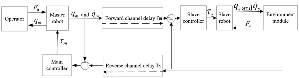
Figure 1. Control structure diagram of teleoperation robot system based on the position error.
As shown in Figure 1, this structure uses the position signals of the master robot and the slave robot as their expected signals. It then designs the controller for the generated error signals to achieve system stability and improve tracking performance. In the teleoperation system, when the slave robot and the working environment contact each other, the weighted position error can be fed back to the operator so that the interaction force can be presented through the position error. The control torque can then be adjusted to reduce the tracking error between the master robot and the slave robot. Therefore, the teleoperation system based on position error control structure is simple.
The proposed teleoperation system with adaptive control
This paper is devoted to solving constant communication delay and dynamic parameter uncertainty in the teleoperation system. For a teleoperation system without considering the master-slave robot mechanism's internal friction and external interference, the joint space dynamic model can be expressed by formulas (14) and (15). An adaptive control method is designed. We apply the designed bilateral controller to the teleoperation system of the master robot and the slave robot. They are composed of two degrees of freedom and two link manipulators.
In the combined teleoperation system introduced in Section Joint space dynamic model of combined teleoperation system, there is a constant communication delay between the forward channel and the reverse channel. Therefore, the combined teleoperation system's adaptive control structure based on the position error structure is shown in Figure 2. The control structure connects the position and velocity signals of the master-slave robot's end arm through forward and reverses channels to form a network. In this network, the desired position and speed signals of the master robot are the end position and speed signals of the slave robot actuator through the reverse channel. The desired position and speed signals of the slave robot are the end position, and speed signals of the main robot actuator passing through the forward channel, that is:
According to the self-adaptive control structure block diagram of the teleoperation system based on the position error structure, the robot's end position's tracking error at the master end and the slave end can be obtained. Thus, the end position's tracking error is obtained through the relationship between the end position of the master robot and the slave robot and the joint angle. That is, the position signal is converted into the joint signal, and the joint position tracking error of the master robot and the slave robot is obtained as follows:
The mathematical models of each module in the teleoperation system are unified into the joint space. They have substituted into the joint space mathematical models of the master robot and the slave robot.
Where, are the estimated values of are the estimated values of unknown constant parameter vectors of the master robot and the slave robot. are the dynamic regression function matrix of the known variables of the master and slave robot joints.
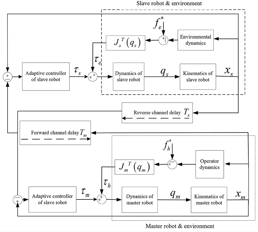
Figure 2. Adaptive control block diagram of teleoperation system based on position error structure.
It can be seen from formula (28) and formula (29) that the dynamic uncertainty parameter vector θzm obtained by a linear transformation of the master robot dynamic combination model is composed of the dynamic uncertain parameters of the master robot and the operator. Similarly, the dynamic uncertainty parameter vector obtained from the linear transformation of the robot dynamics combination model consists of the uncertain parameters of the slave robot and the environment dynamics form. In this way, we include the external force of the operator and the external force of the environment into the dynamic uncertainty vector θzm, θzs of the system.
Controller design and stability analysis of teleoperation system
The control objective of the teleoperation system based on the position error control structure in this section is to design an adaptive controller at the master end and an adaptive controller at the slave end for the master robot and the slave robot, respectively, to solve the problem that the dynamic parameters of the master robot and the slave robot are uncertain. The communication channel has a constant time delay, ensuring the system's stability and making the system have stable performance. It has good instantaneous characteristics and transparency, thus improving the tracking performance of the system (Liu et al., 2020).
Therefore, based on the position error control structure, two-sided adaptive controllers are designed for the master robot and the slave robot, respectively. The stability and position tracking of the teleoperation system's performance is analyzed using high calculus Lyapunov Krasovski functional.
Controller design
Now we start to design non-linear bilateral adaptive controllers. Firstly, to stabilize the motion of the master robot and the slave robot in the teleoperation system, t → ∞, when . The following auxiliary variables need to be defined:
Where λi is the diagonal matrix of positive definite constant and represents the weight of tracking error.
Since the acceleration signal cannot be used in a teleoperation system, a regression matrix about tracking error is defined as follows:
Formula (33) shows that when ei → 0, there were , i = m, s.
Thus, the adaptive controller of the master robot and the adaptive controller of the slave robot is designed as:
Where, for convenience, here i = m, s, ki is a positive definite constant diagonal matrix, which represents the proportional gain. The term is a model-based term, that is used to compensate for the error. is the estimated value of θi. The proportion term for auxiliary variables si is the additional term of error compensation. The other term βiėi is used to eliminate the additional energy dissipation caused by a time delay, where βi is the diagonal matrix of positive definite constant, representing the dissipation coefficient.
By substituting formula (34) and formula (35) into formula (14) and formula (15), the following results are obtained:
Among them, Δθzm, Δθzs, respectively represents the estimated error of θzm, θzs, which satisfies .
Usually, the adaptive law proposed by Slotine and Li (1991) is directly selected:
Among them, i = m, s, Γi is the positive definite diagonal constant matrix gain.
The above estimation method has been widely used in adaptive control applications. However, Slotine and Li (1991) also pointed out that if the reference signal does not meet the persistent excitation conditions, the above estimation accuracy cannot be guaranteed. Therefore, to improve the adaptive estimation value's accuracy and convergence rate, the above formula's estimation method is improved using the input torque estimation error. The adaptive estimation law of uncertain parameters θzi is defined as follows:
Among them, for the sake of convenience i = m, s, denotes the estimation error of calculating input torque used for correcting the estimated value. Here Δθi represents the estimation error. Γi(t) = diag(γ1(t), ···, γp(t)) is the adaptive gain matrix, satisfying Γi(t) > 0, , where . an. bn are the constants, and fn(υ) ≥ 0, n = {1, ···, p}. pi(t) is the low-pass filtered signal of which satisfies the formula , where μ and η are constant and ξ1 and ξ2 are constant too. According to the robust control technique in Nuño et al. (2010), the coefficients ξ1 can be defined as:
where α, δ is the constant. is the minimum eigenvalue of .
Analysis of system stability and tracking performance
In this paper, the stability of closed-loop systems with time delay is described in formulas (14) and (15), adaptive bilateral control laws in formula (36) and formula (37), and adaptive laws shown in formula (39) are analyzed. The joint position tracking error ėm, ės and the estimation error of the adaptive law Δθzm, Δθzs of the teleoperation system are bounded. The velocity and tracking error ėm, ės converge to zero.:
For a teleoperation robot system, a high calculus Lyapunov Krasovski candidate function V(t) is defined:
Where, , , , and , for the sake of convenience, i = m, s.
From property (4), we know that Mm(qm), Ms(qs) are symmetric positive definite matrices, Γi(t), ki, βi are positive definite matrices. Therefore, V(t) is also positive definite matrices.
By deriving the two sides of the candidate Lyapunov function formula (41), the following results are obtained:
According to property (5):
Because , so there are:
By substituting formulas (43) and (44) into formula (42), the results are as follows:
From the previous definition, Γi(t) > 0 and are negative semidefinite, then
Where, Bi, ki, βi is the positive definite diagonal constant, is semi-positive definite, therefore .
Therefore, V(t) ≥ 0 while . The auxiliary variables si of the system, the tracking error ei, and the estimation error Δθzi of the adaptive law are bounded. Then we use the theorem of Barbalat to know that the asymptotic approach to 0, then at that time t → ∞, there are si → 0, ėi → 0.
Thus, , define r(t) = xm + xs. We can get the following conclusions:
Laplace transform formula (47) into: ,
It can be inferred that . that is ẋm + ẋs → 0 when t → ∞.
Similarly, define r(t) = xm − xs, get ẋm − ẋs → 0 as t → ∞. Therefore, it is proved that the velocity of the master robot and the slave robot approaches zero asymptotically, that is ẋm, ẋs → 0, as t → ∞. Considering the auxiliary variables si = ẋi + λiei → 0, the position tracking error converges to 0.
Simulation verification
The master robot and the slave robot are simulated, respectively, in free motion and in contact with the operator and the environment to verify the above control algorithm's effectiveness. In these two cases, the position tracking and force tracking of the traditional adaptive control algorithm in Nuño et al. (2010) and the designed adaptive control method are compared.
In this paper's simulation experiment, the teleoperation system structure is selected, as shown in Figure 3. The master and slave robots of the teleoperation system with time-delay force feedback are selected as the two degrees of freedom two-link rotary manipulator robots. Its dynamic mathematical model is formula (48) ~ formula (52). As shown in Figure 3, the kinematic Jacobian matrices of the master and slave robots of the closed-loop delay teleoperation system are:
Among which,
Here, g is the acceleration of gravity , , p3 = mcl1lc2, p4 = m1lc2 + m2l1, and p5 = m2lc2.
The end effector position of the master and slave robots in the system is expressed in the plane rectangular coordinate system as follows:
In the simulation verification, the dynamic parameters of the master robot and the slave robot are shown in Table 1.
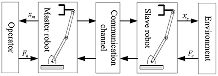
Figure 3. Schematic diagram of teleoperation system selected by simulation.

Table 1. Physical parameters of master-slave robot double joint manipulator.
Simulation of free motion
Firstly, in the teleoperation system based on the position error structure shown in Figure 2, the effectiveness of the adaptive control method proposed in this chapter is verified by simulation in the case of the free motion of the master robot and the slave robot. There is no contact force in the process of the master robot and the robot, so the expression formula is Fh = 0 and Fe = 0.
The simulation experiment is carried out by using the MATLAB Simulink tool. The experiment proves that the bilateral teleoperation system with the dynamic model of formula (14) and formula (15) is stable under the control of adaptive controller type formula (34) and formula (35) and adaptive law formula (39). The position tracking error is bounded and can converge to near 0.
In the experiment, it is assumed that the dynamic parameters of the master robot and the slave robot are unknown. Let the dynamic parameter vectors of the master robot and slave robot be:
Here , , and κ = mcl1lc2. The initial parameters of the master robot and the slave robot of the teleoperation system are set as initial position parameters xm(0) = [0.184, 2.6389] and xs(0) = [3, 0]. The initial dynamic uncertainty parameter vector is . The gain parameters of the master controller and slave controller are set km = diag(30, 30) and ks = diag(30, 30), dissipation coefficient βm = βs = diag(0.8, 0.6), and λm = λs = diag(5, 5). The adaptive gain matrix of master adaptive law and slave adaptive law is as follows:
And the constant parameters of the adaptive law and the slave adaptive law are set to αm = αs = 1, δm = δs = 1, ξ2m = ξ2s = 0.8, μm = μs = 1, and ηm = ηs = 1. Acceleration of gravity g = 9.81. In the teleoperation system, the forward channel delay and the reverse channel delay are Tm = Ts = 0.5 s. The simulation results are shown in Figures 4, 5.
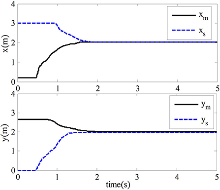
Figure 4. Trajectory map of end position tracking.
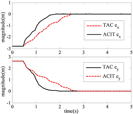
Figure 5. Tracking error of the end position of the robot.
The traditional adaptive two-sided control method of the time-delay teleoperation system in Nuño et al. (2010) to illustrate the advantages of the two-sided controller are compared and analyzed. The control law is as follows:
The adaptive law is as follows:
Where ri = ėi + αiei, αi, Ki, Lid are constant diagonal matrix. In the simulation experiment, after repeated debugging, we can analyze and set the parameters of bilateral controller and adaptive law as αm = αs = 0.25, Km = Ks = diag(100, 100), and Lmd = Lsd = diag(40, 40).
Simulation with contact
In the case of contact motion, the operator contacts the master robot. From the contact between the robot and the environment, the effectiveness of the adaptive bilateral controller scheme designed in this chapter for the time-delay force feedback teleoperation system is verified.
This section also uses MATLAB SIMULINK for simulation verification. In the simulation teleoperation system and the environment space model is set. The environmental dynamic parameters are set as me = 0.1 kg, where the mass coefficient me = 0.1 kg, damping coefficient be = 20 Ns/m, elastic coefficient be = 20Ns/m, and external environmental force are set to simulate the passive environment. According to the operator model, the external force of the operator is set as . Moreover, its dynamic parameters are set as: Mh = mhI, Bh = bhI, and Kh = khI, where the mass coefficient mh = 0.2 kg, damping coefficient bh = 50 Ns/m, and elastic coefficient are set to kh = 100Ñ/m.
In the experiment, it is considered that the dynamic parameters of the master robot and the slave robot are unknown, and the bilateral adaptive controller can solve this problem. According to properties (6), the dynamic models of the master robot and the slave robot are transformed linearly. The dynamic uncertain parameter vectors are obtained as follows:
By introducing the parameters in Table 1 into formula (59) and formula (60), the actual dynamic parameter vector can be calculated as follows:
In the case of contact, the initial positions of the master robot and the slave robot of the teleoperation system are the same. That is, the initial position parameters xm(0) = [0.184, 2.6389] and xs(0) = [0.184, 2.6389]. The parameters of the master robot and the slave robot are shown in Table 1. Acceleration of gravity g = 9.81. Set the initial dynamic parameter vector as follows:
After repeated debugging, the design parameters of the master controller and slave controller formula (33) and formula (34) are set as follows km = diag(50, 50) and ks = diag(50, 50). gain parameter is βm = βs = diag(0.8, 0.6) and λm = λs = diag(5, 5). Dissipation coefficient is βm = βs = diag(0.8, 0.6). The adaptive law of the master robot and the slave robot is formula (3-14). After repeated debugging, the adaptive gain matrix of the master robot and the slave robot is: and . The constant parameters of the adaptive law and the slave adaptive law are set to αm = αs = 1, δm = δs = 1, ξ2m = ξ2s = 0.8, μm = μs = 1, and ηm = ηs = 1. In the teleoperation system, the forward channel delay and the reverse channel delay are Tm = Ts = 0.5s. The experimental results are shown in Figure 7.
The adaptive two-sided controller described in formula (57) and adaptive law described in formula (58) in Nuño et al. (2010) are compared under the same environmental conditions to illustrate the advantages of the two-sided controller. The parameters of the controller in Nuño et al. (2010) are set to αm = αs = 5, Km = Ks = 200I, Lmd = Lsd = 40I.
Results and findings
Simulation results of free motion
This section verifies the proposed adaptive control method's effectiveness while the master robot and slave robot are in free motion. The proposed method is compared with the method mentioned in Nuño et al. (2010), which could not be fully discussed and explained in this paper. In the simulation experiment, when the teleoperation system moves freely, the master robot and the slave robot are not affected by external forces. Their position tracking trajectory is shown in Figure 4. We can tell from Figure 4 that the slave robot of the teleoperation system can track the position of the master robot within 1.8 s and ensure the stability of the closed-loop system with time-delay force feedback.
The simulation results of the comparative experiment are shown in Figures 5, 6. In the figures, ACIT (adaptive bilateral control with improved tracking performance) represents the bilateral adaptive control method designed. TAC (traditional adaptive bilateral controller) represents the traditional bilateral adaptive control method in Nuño et al. (2010).
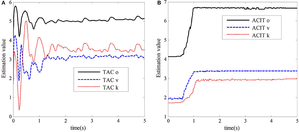
Figure 6. Estimated values of the dynamic parameter vector. (A) The estimated value of TAC. (B) The estimated value of ACIT.
Figure 5 shows the end position tracking error curves of the master robot and the slave robot of the teleoperation system with time-delay force feedback under the two control methods. From this graph, we can observe that the time of position tracking error convergence to zero in the two-sided adaptive control method is about 1.8 s. In comparison, the traditional adaptive control method is about 2.8 s.
Figures 6A,B show the estimated values of the dynamic uncertain parameter vector of the slave robot of the teleoperation system under the traditional bilateral adaptive control method and the bilateral adaptive control method designed in this chapter, respectively. For the time-delay teleoperation system with uncertain dynamic parameters, the adaptive bilateral control method designed in this chapter can quickly converge to the real value in 0.5 s compared with the traditional two-sided adaptive control method in Nuño et al. (2010). However, in the traditional adaptive control method, it takes 1.8 s to converge to the region near the real value, which is unstable and fluctuates greatly. Its accuracy is relatively low.
Simulation results with contact
In the case of contact motion, the operator contacts the master robot. From the contact between the robot and the environment, the effectiveness of the adaptive bilateral controller scheme designed in this chapter for the time-delay force feedback teleoperation system is verified. The experimental results are shown in Figure 7.
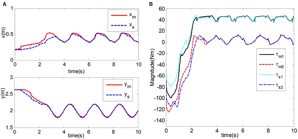
Figure 7. Simulation results. (A) End position trajectory of Master and slave robot. (B) Input torque of master and slave robot joints.
Figure 7A shows the position tracking the trajectory of the mechanical end of the master robot and the slave robot of the teleoperation system. We can observe that the position curves of the master robot and the slave robot almost coincide in about 3.5 s. In Figure 7B, The input torques of joint 1 and joint 2 of the master robot and slave robot are displayed. The slave robot of the teleoperation system can track the position of the upper master robot under the contact condition, and the time-delay force feedback teleoperation system can maintain stability.
The comparison of experimental results shows that the estimation error of uncertain vector of dynamic parameters of the teleoperation system with time-delay force feedback under the two control methods and the tracking error curve of the master robot and the slave robot end position is shown in Figures 8, 9. In the figure, TAC is used to represent the method in Nuño et al. (2010). ACIT represents the method designed in this paper.
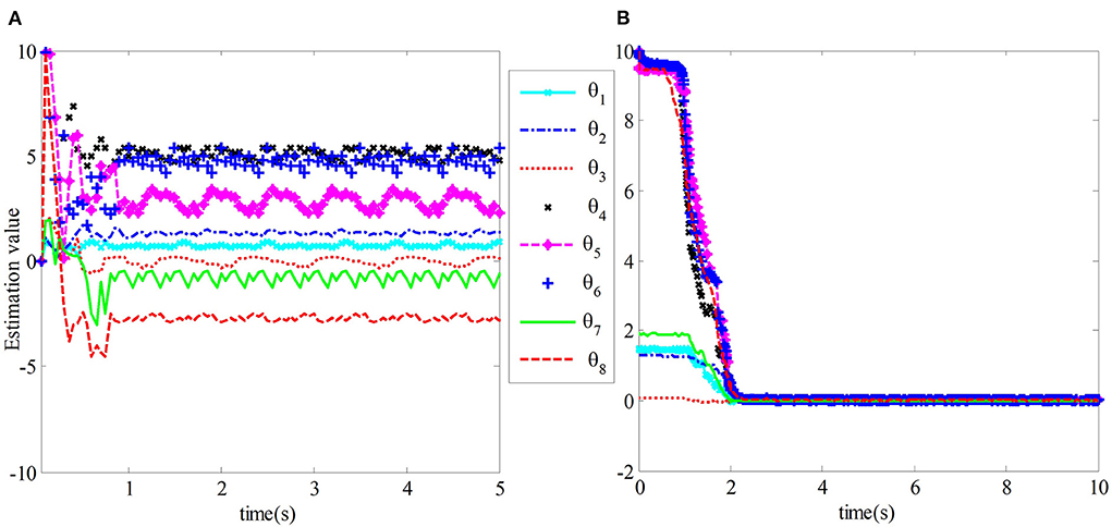
Figure 8. The estimation error of θs of the slave robot dynamic parameter vector. (A) The estimation error of TAC. (B) The estimation error of ACIT.

Figure 9. Position tracking error comparison of master-slave robot.
Figure 8A shows the estimation error of the uncertainty vector θs of the robot dynamic parameters for the teleoperation system under the traditional adaptive control method in Nuño et al. (2010). We can observe that the position tracking convergence speed of the teleoperation system under the traditional adaptive control method is slow, and the tracking error accuracy is not high. At the same time, its adaptive estimation converges slowly and fluctuates greatly, which will affect the control performance of the system in practical application. Figure 8B shows the estimated error of the teleoperation system from the uncertain vector θs of robot dynamic parameters under the control method designed in this paper. The estimated vector value from the uncertainty of robot dynamic parameters can quickly converge to the true value in 2 s.
Figure 9 compares the traditional adaptive control method and the control method designed in this chapter. We can observe that the adaptive control method in this paper has better tracking performance.
Conclusions
Aiming at the uncertainty of dynamic parameters and time delay in the system, a bilateral adaptive control method based on PEB control structure is designed for a class of time-delay force feedback teleoperation systems without external interference and internal friction. The stability and tracking performance of the closed-loop constant time delay teleoperation system is analyzed by Lyapunov stability theory. Finally, the controller designed in this paper is successfully applied to the teleoperation system composed of a two-degree freedom rotating manipulator as a master robot and a slave robot. The advantages of this method are verified by simulation under the conditions of free motion and environmental forces and with contact and environmental forces, respectively. The control performance of this method is compared with that of the traditional adaptive bilateral control method for the time-delay teleoperation system, and the effectiveness of this method is analyzed by experiments. Finally, the method is proved to have good control performance.
The bilateral controller designed in this paper has the following advantages:
(1) Based on the position error structure, the operator and environment's dynamic parameters can be included in the unknown vector of the whole system for estimation to avoid the influence of uncertain parameters in the operator and environment model on the system.
(2) The estimation error is used to compensate for the adaptive estimation law to improve the system's tracking performance to improve the adaptive estimation accuracy and convergence speed.
(3) By compensating for the dissipation caused by a time delay, the controller's performance is improved, thus ensuring the system's stability and improving the system's tracking performance.
There are still many possible improvements and experiments that could be performed based on this paper. For example, for more complex cases, such as non-linear models and time-varying cases, the control of teleoperation systems needs to be further studied. Besides, This paper only analyzes and verifies the control method of the time-delay force feedback teleoperation system in this article from two aspects of theory and simulation. There may be some problems that have not been considered in the actual system. Therefore, in future research work, the above method should be applied to the real teleoperation system for verification and improvement, so as to make it more practical.
Data availability statement
The original contributions presented in the study are included in the article/supplementary material, further inquiries can be directed to the corresponding author/s.
Author contributions
WZ and BY contributed to the conceptualization. ShL contributed to the methodology of this work and supervision. SiL, YB, and LY completed the writing of the original manuscript. XZ completed technical work such as model designing. XZ, SiL, and YB contributed to formal analysis and data curation. SiL, WZ, and LY carried out writing review and editing. WZ contributed to funding acquisition. SiL, YB, XZ, BY, ShL, LY, and WZ read and agreed to the published version of the manuscript. All authors contributed to the article and approved the submitted version.
Funding
This work was jointly supported by the Sichuan Science and Technology Program (2021YFQ0003).
Conflict of interest
The authors declare that the research was conducted in the absence of any commercial or financial relationships that could be construed as a potential conflict of interest.
Publisher's note
All claims expressed in this article are solely those of the authors and do not necessarily represent those of their affiliated organizations, or those of the publisher, the editors and the reviewers. Any product that may be evaluated in this article, or claim that may be made by its manufacturer, is not guaranteed or endorsed by the publisher.
References
Bejczy, A. K. (1994). Toward advanced teleoperation in space. Prog. Astron. Aeron. 161, 107–107. doi: 10.2514/5.9781600866333.0107.0138
Bessa, W. M., Dutra, M. S., and Kreuzer, E. (2010). An adaptive fuzzy sliding mode controller for remotely operated underwater vehicles. Robot. Auton. Syst. 58, 16–26. doi: 10.1016/j.robot.2009.09.001
Cho, H. C., and Park, J. H. (2005). Impedance control with variable damping for bilateral teleoperation under time delay. JSME Int. J. Ser. C Mech. Syst. Mach. Elem. Manufac. 48, 695–703. doi: 10.1299/jsmec.48.695
Dehghan, S. A. M., Koofigar, H. R., and Ekramian, M. (2016). “Nonlinear bilateral control of 4-channel teleoperation systems using adaptive force estimator,” in 2016 20th International Conference on System Theory, Control and Computing (ICSTCC), 102–106. doi: 10.1109/ICSTCC.2016.7790648
DiMaio, S., Hanuschik, M., and Kreaden, U. (2011). “The da Vinci surgical system,” in Surgical Robotics, eds J. Rosen, B. Hannaford, R. Satava (Boston, MA: Springer), 199–217. doi: 10.1007/978-1-4419-1126-1_9
Do, N. D., and Namerikawa, T. (2009). “Impedance control for force-reflecting teleoperation with communication delays based on IOS small gain theorem,” in 2009 ICCAS-SICE 2009 (Fukuoka), 4079–4086.
Franken, M., Misra, S., and Stramigioli, S. (2012). “Stability of position-based bilateral telemanipulation systems by damping injection,” in 2012 IEEE International Conference on Robotics and Automation 2012 (Saint Paul, MN), 4300–4306. doi: 10.1109/ICRA.2012.6224572
Haddadi, A., Razi, K., and Hashtrudi-Zaad, K. (2015). Operator dynamics consideration for less conservative coupled stability condition in bilateral teleoperation. IEEE/ASME Trans. Mechatron. 20, 2463–2475. doi: 10.1109/TMECH.2014.2385637
Hastrudi-Zaad, K., and Salcudean, S. (1999). “On the use of local force feedback for transparent teleoperation,” in Proceedings 1999 IEEE International Conference on Robotics and Automation (Cat No 99CH36288C) (Detroit, MI), 1863–1869. doi: 10.1109/ROBOT.1999.770380
Joinié-Maurin, M., Bayle, B., and Gangloff, J. (2011). “Force feedback teleoperation with periodical disturbance compensation,” in 2011 IEEE International Conference on Robotics and Automation (Shanghai), 4828–4833. doi: 10.1109/ICRA.2011.5980496
Kim, B.-Y., and Ahn, H.-S. (2013). A design of bilateral teleoperation systems using composite adaptive controller. Control Eng. Pract. 21, 1641–1652. doi: 10.1016/j.conengprac.2013.08.013
Lawrence, D. (1994). A stability and transparency in bilateral teleoperation. IEEE Trans. Robot. Autom. 9, 605–620. doi: 10.1109/70.258054
Liu, H., Pan, Y., Cao, J., Wang, H., and Zhou, Y. (2020). Adaptive neural network backstepping control of fractional-order nonlinear systems with actuator faults. IEEE Trans. Neural Netw. Learni. Syst. 31, 5166–5177. doi: 10.1109/TNNLS.2020.2964044
Liu, X., and Tavakoli, M. (2011). Adaptive inverse dynamics four-channel control of uncertain nonlinear teleoperation systems. Adv. Robot. 25, 1729–1750. doi: 10.1163/016918611X584668
Liu, X., Zheng, W., Mou, Y., Li, Y., and Yin, L. (2021). Microscopic 3D reconstruction based on point cloud data generated using defocused images. Measure. Control 54, 1309–1318. doi: 10.1177/00202940211033881
Malysz, P., and Sirouspour, S. (2009). Nonlinear and filtered force/position mappings in bilateral teleoperation with application to enhanced stiffness discrimination. IEEE Trans. Robot. 25, 1134–1149. doi: 10.1109/TRO.2009.2017803
Nuño, E., Ortega, R., Barabanov, N., and Basañez, L. (2008). A globally stable PD controller for bilateral teleoperators. IEEE Trans. Robot. 24, 753–758. doi: 10.1109/TRO.2008.921565
Nuño, E., Ortega, R., and Basañez, L. (2010). An adaptive controller for nonlinear teleoperators. Automatica 46, 155–159. doi: 10.1016/j.automatica.2009.10.026
Polushin, I. G., Liu, P. X., Lung, C.-H., and On, G. D. (2010). Position-error based schemes for bilateral teleoperation with time delay: theory and experiments. J. Dyn. Syst. Measure. Control 132:031008. doi: 10.1115/1.4001215
Sayers, C., and Paul, R. (1994). Coping with delays-controlling robot manipulators underwater. Indus. Robot. 21, 24–26. doi: 10.1108/EUM0000000004162
Slotine, J.-J. E., and Li, W. (1991). Applied Nonlinear Control. Englewood Cliffs, NJ: Prentice Hall.
Su, H., Hu, Y., Karimi, H. R., Knoll, A., Ferrigno, G., De Momi, E., et al. (2020a). Improved recurrent neural network-based manipulator control with remote center of motion constraints: experimental results. Neural Netw. 131, 291–299. doi: 10.1016/j.neunet.2020.07.033
Su, H., Qi, W., Hu, Y., Karimi, H. R., Ferrigno, G., De Momi, E., et al. (2020b). An incremental learning framework for human-like redundancy optimization of anthropomorphic manipulators. IEEE Trans. Indus. Inform. 18, 1864–1872. doi: 10.1109/TII.2020.3036693
Su, H., Qi, W., Yang, C., Sandoval, J., Ferrigno, G., De Momi, E., et al. (2020c). Deep neural network approach in robot tool dynamics identification for bilateral teleoperation. IEEE Robot. Autom. Lett. 5, 2943–2949. doi: 10.1109/LRA.2020.2974445
Su, H., Schmirander, Y., Li, Z., Zhou, X., and Momi, E. D. (2020d). “Bilateral teleoperation control of a redundant manipulator with an rcm kinematic constraint,” in 2020 IEEE International Conference on Robotics and Automation (ICRA), 4477–4482. doi: 10.1109/ICRA40945.2020.9197267
Tang, Y., Liu, S., Deng, Y., Zhang, Y., Yin, L., Zheng, W., et al. (2020). Construction of force haptic reappearance system based on geomagic touch haptic device. Comput. Methods Prog. Biomed. 190:105344. doi: 10.1016/j.cmpb.2020.105344
Wang, Y., Tian, J., Liu, Y., Yang, B., Liu, S., Yin, L., et al. (2021). Adaptive neural network control of time delay teleoperation system based on model approximation. Sensors 21:7443. doi: 10.3390/s21227443
Wright, J., Hartman, F., Cooper, B., Maxwell, S., Yen, J., Morrison, J., et al. (2006). Driving on mars with RSVP. IEEE Robot. Autom. Mag. 13, 37–45. doi: 10.1109/MRA.2006.1638014
Xu, C., Yang, B., Guo, F., Zheng, W., and Poignet, P. (2020). Sparse-view CBCT reconstruction via weighted Schatten p-norm minimization. Opt. Exp. 28, 35469–35482. doi: 10.1364/OE.404471
Yokokohji, Y., and Yoshikawa, T. (1994). Bilateral control of master-slave manipulators for ideal kinesthetic coupling-formulation and experiment. IEEE Trans. Robot. Autom. 10, 605–620. doi: 10.1109/70.326566
Zhang, W., Yao, G., Yang, B., Zheng, W., and Liu, C. (2022). Motion prediction of beating heart using spatio-temporal LSTM. IEEE Signal Process. Lett. 29, 787–791. doi: 10.1109/LSP.2022.3154317
Zhang, Z., Liu, Y., Tian, J., Liu, S., Yang, B., Xiang, L., et al. (2021). Study on reconstruction and feature tracking of silicone heart 3D surface. Sensors 21:7570. doi: 10.3390/s21227570
Keywords: adaptive bilateral control method, Lyapunov stability theory, time delay teleoperation system, uncertain dynamics, force feedback, PEB control structure
Citation: Lu S, Ban Y, Zhang X, Yang B, Liu S, Yin L and Zheng W (2022) Adaptive control of time delay teleoperation system with uncertain dynamics. Front. Neurorobot. 16:928863. doi: 10.3389/fnbot.2022.928863
Received: 26 April 2022; Accepted: 13 June 2022;
Published: 22 July 2022.
Edited by:
Yongping Pan, National University of Singapore, SingaporeReviewed by:
Heng Liu, Guangxi University for Nationalities, ChinaJing Guo, Guangdong University of Technology, China
Copyright © 2022 Lu, Ban, Zhang, Yang, Liu, Yin and Zheng. This is an open-access article distributed under the terms of the Creative Commons Attribution License (CC BY). The use, distribution or reproduction in other forums is permitted, provided the original author(s) and the copyright owner(s) are credited and that the original publication in this journal is cited, in accordance with accepted academic practice. No use, distribution or reproduction is permitted which does not comply with these terms.
*Correspondence: Wenfeng Zheng, d2luZmlybXNAdWVzdGMuZWR1LmNu