 Xianfang Tong
 Yanzheng Zhu
94% of researchers rate our articles as excellent or good
Learn more about the work of our research integrity team to safeguard the quality of each article we publish.
Find out more
ORIGINAL RESEARCH article
Front. Neurorobot. , 20 October 2022
Volume 16 - 2022 | https://doi.org/10.3389/fnbot.2022.1022839
This article is part of the Research Topic Hybrid Intelligent Algorithms Based Learning, Optimization, and Application to Autonomic Control Systems, Volume II View all 6 articles
Motorized functional electrical stimulation (FES) cycling has been demonstrated to have numerous health benefits for individuals suffering from neurological disorders. FES-cycling is usually designed to track the desired trajectories in real time. However, there are input delays between the exertion of the stimulation and the corresponding muscle contraction that potentially destabilize the system and undermine training efforts. Meanwhile, muscle fatigue gives rise to a time-varying input delay and decreased force. Moreover, switching between FES and motor control can be chattering and destabilizing owing to the high frequency. This article constructs Lyapunov-Krasovskii functionals to analyze the stability and robustness of the nonlinear cycling system with time-varying input delay. A new average dwell time condition is then provided to ensure the input-to-state stability of the considered systems. Finally, numerical simulations are illustrated to verify the effectiveness of the developed controller.
Functional electrical stimulation (FES) induced cycling has shown a large number of health benefits, such as improving muscular strength (Bélanger et al., 2000), cardiovascular effects (Hooker et al., 1992), improvements in bone mineral density (Mohr et al., 1997), and so on. Therefore, FES-cycling is used for rehabilitation exercises for individuals with various neurological disorders including Parkinson's Disease, Multiple Sclerosis, traumatic brain injury, spinal cord injury, and stroke (Petrofsky, 2003; Cousin et al., 2019). It effectively improves the overall quality of life and activities of daily living of affected patients. However, there are also several challenges to the use of the closed-loop FES-cycling control approach. For instance, there are time-varying delay muscle responses to electrical stimulation (Obuz et al., 2020), unmodeled disturbances in the dynamic model, problems with founding an optimal stimulation pattern (Einar et al., 2004), and the stimulation intensity-force mapping changes as the muscle fatigues (Downey et al., 2017), etc.
An electromechanical delay (EMD) exists between the electrical stimulation input and the muscle force production, which can be modeled as an input delay (Jezernik et al., 2004; Alibeji et al., 2015; Merad et al., 2016; Obuz et al., 2020). Meanwhile, this delay is time-varying due to muscle fatigue, which results from FES eliciting, ranging from 75 to 200 ms (Ha et al., 2016). The EMD might destabilize the presented system or even degrade the performance of designed controllers (Kei et al., 2008; Alibeji et al., 2015). Therefore, the EMD presents inevitable challenges for the FES-cycling system, which can also be affected by a large number of factors, such as age (Burgess et al., 2009; Yavuz et al., 2010), gender (Yavuz et al., 2010), stimulus parameters (Downey et al., 2017), fatigue (Laura et al., 2007), and so on. Additionally, the unknown and nonlinear mapping from the constant stimulation intensity to the generated muscle force (Ding et al., 2002) can also present challenges. Hence, it must be robust to the time-varying delays and the nonlinear muscle dynamics for a closed-loop FES controller to perform the desired tracking goals. In recent decades, the EMD response of muscles has been considered when developing neuromuscular electrical stimulation (NMES)/FES controller (Sharma et al., 2011; Iasson et al., 2013; Alibeji et al., 2015; Merad et al., 2016; Allen et al., 2022). For instance, a novel predictor-type method has been developed to address the EMD in Sharma et al. (2011). However, the EMD is assumed to be constant and known to ensure uniformly ultimately bounded tracking. A globally asymptotical tracking controller is designed in Iasson et al. (2013) by assuming that there is an unknown constant delay and precise model knowledge of limb dynamics. The feedback controller is established to compensate for the known time-varying delay during isometric contractions in Merad et al. (2016). In practice, the EMD usually has an unknown time-varying delay, but it has not been fully considered to date, which is one of the main motivations for this study.
In more recent years, switched systems have received increasing attention because many practical systems can be modeled as switched systems. Motivated to improve FES-cycling performance and to complete rehabilitation tasks in different periods, a switching control strategy has been proposed in Cousin et al. (2019) and Allen et al. (2022). For instance, a cadence switching controller is employed to ensure that the motorized FES cycling system is globally exponentially stable (Cousin et al., 2019). The experiment results validate the effectiveness of the developed controller to improve the tracking performance. Similarly, a kind of robust switched controller is designed to deal with an unknown time-varying input delay in Allen et al. (2022), and semi-globally exponential tracking to an ultimate bound is guaranteed. As a popular approach, Lyapunov-Krasovskii functionals have been frequently used to analyze the stability of time-delay systems, which are very effective at deriving the stability conditions for time-delay systems. However, the stability conditions of nonlinear switched systems with time-varying delays have rarely been obtained, except for a few sporadic results (Wang et al., 2014). Hence, structuring an appropriate Lyapunov-Krasovskii functional to analyze the stability of a class of nonlinear time-varying delay switched systems, which are derived from the FES-cycling systems, is another of the main motivations of this article.
Motivated by the aforementioned discussions, a kind of tracking controller is developed for a nonlinear FES-cycling system with time-varying input delays and external disturbance in this paper. First, the mathematical model is structured using the Euler-Lagrange equations for a class of rider-tricycle systems. Based on the transferred efficiency from the muscle force to the crank, the corresponding control system is decoupled into FES and motor drive subsystems to decrease the complexity of the original nonlinear system. Then, an appropriate state-dependent switching control law is designed for these two subsystems to alleviate muscle fatigue and prolong the duration of rehabilitation training. Meanwhile, the time-varying input delay is assumed to be unknown, but it has a known upper bound. The input-to-state stability (ISS) is guaranteed for the presented FES-cycling system by using the constructed Lyapunov-Krasovskii functional, and the corresponding robust controller is designed to achieve the desired performance goal. Moreover, an average dwell time (ADT) constraint is considered between two switchings to avoid chattering induced by high frequency switching. A numerical simulation is presented to illustrate the effectiveness of the designed controller. The main contributions of this paper can be summarized as follows:
• The complex rider-tricycle system is decomposed into two subsystems by a class of switching control strategies. Meanwhile, the EMD is considered a time-varying input delay in the system.
• By constructing an appropriate Lyapunov-Krasovskii functional and introducing the ADT technique, the input-to-state stability (ISS) condition is derived for the augmented switched system with unknown time-varying input delays.
• The upper bound of time delays is only needed, which relaxes the restriction to the time-varying input delay, and hence the conservatism is decreased in this paper.
Notation: The notation used in this paper is fairly standard. ℝ and ℝ+ denote the set of real numbers and positive real numbers, respectively. The superscript T denotes matrix transposition, and symbol |•| denotes the Euclidean norm of a real vector. C1 stands for the space of first-order continuously differentiable functions. I is the identity matrix with appropriate dimensions. If |w|∞ ≤ ∞ exists, then it holds that .
At first, the legs of the rider are modeled as the form of the two-link. The revolute joint (hip) and the rider's feet are fixed to the cycle seat and pedals, respectively. The pedal crank arms are limited to rotate on a circle around the center of the crank with π radians. All the parameters of the rider and tricycle are transformed into those of the crank. In particular, the diagram of the presented rider-tricycle system is shown in Figure 1A. The dynamics of the rider-tricycle system can be modeled by using the Euler-Lagrange framework as used in Einar (2002):
where : ℝ ≥ 0 → ℝ, : ℝ ≥ 0 → ℝ, θ : ℝ ≥ 0 → Θ denote the crank acceleration, cadence, and angle, respectively. The set Θ ⊆ ℝ denotes all possible crank angles. The inertial effects, centripetal-Coriolis and viscoelastic damping effects, gravitational effects, passive viscous forces, and disturbance are denoted by M(θ):Θ → ℝ+, , G(θ):Θ → ℝ+, , and d(t):ℝ ≥ 0 → ℝ, respectively. The crank torque (including motor and FES stimulated muscle contractions) is denoted by νcrank ∈ ℝ, which can be defined as
where and represent the unknown time-varying input delay of motor and FES stimulated muscle contractions, respectively. Additionally, the torques due to the motor and muscle contractions are denoted by and , respectively, which are defined as
where u(t − τM(t)):ℝ × ℝ ≥ 0 → ℝ and u(t − τe(t)):ℝ × ℝ ≥ 0 → ℝ stand for the FES and motor input with time-varying delays, respectively. The parameters ke, are selectable constants, where m ∈ M ≜ {GR, QR, HR, GL, QL, HL} indicates gluteal (G), hamstrings (H), and quadriceps (Q) femoris muscle groups in right (R) and left (L) limbs, respectively. The right-continuous switching signals for motor and each muscle group are denoted by and , respectively, which are defined as
where ΘFES denotes the union of all stimulation regions that are based on the torque transfer ratio of muscle groups and is defined as . Each muscle's desired contraction region, i.e., efficient forward pedaling is denoted by Θm, defined as Θm ≜ {θ ∈ Θ|Tm(θ) > εm}, m ∈ 𝕄, where Tm(θ):Θ → ℝ and denote a muscle contraction torque transfer ratio and a selected lower threshold, respectively. Moreover, the remainder regions (i.e., motor regions) of the crank cycle are denoted by ΘDZ, which is defined as ΘDZ ≜ Θ/ΘFES. In particular, the regions of ΘFES and ΘDZ are illustrated in Figure 1B. For any finite time interval, it assumes that only a finite number of switches and no jump occurs in the states at a switching moment. Meanwhile, T1, T2, and T3 denote the time when the relative error first reaches c1, c2, and c3, respectively, where , , and are selectable constants. The parameter θ ∈ ΘFES, and c1 < er ≤ c2 indicates the muscle contraction torque is too small to track the desired trajectory and the torque needs to be provided by the motor. In contrast, θ ∈ ΘFES, er ≤ c1 indicates that the muscle contraction torque can effectively track the desired trajectory. Moreover, to avoid secondary injury during rehabilitation, the system will stop running once the relative error is greater than c3. The relative error is denoted by er, which is defined as
where xr:ℝ ≥ 0 → ℝ and x:ℝ ≥ 0 → ℝ denote the desired and actual trajectories, respectively. Substituting Equations (2) and (3) into Equation (1) yields the switched system
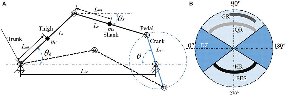
Figure 1. (A) Model of the rider-tricycle system (left). (B) Crank cycle pattern of FES and motor regions (right). The stimulation regions of the right leg (GR, QR, HR) differ 180° from the left leg (GL, QL, HL). Here, the stimulation regions of the left leg are omitted for simplicity.
Remark 1. As shown in Sharma et al. (2011), the EMD significantly increases with FES induced fatigue. Therefore, after the error reaches c1 for the moment (T1), with muscle fatigue and time delays, the muscle force will not provide enough force to track the ideal trajectory under the error c1. Then, the system will be switched to assist mode and the motor provides partial force to reduce the muscle load and the error between T1 and T2. The system will be switched to passive mode between T2 and T3, which is powered only by the motor. To avoid injury to users, the system stops running when the error reaches c3.
To facilitate controller development, we define . After substituting them into the dynamic system (Equation 7), it obtains that
Equation (7) can be rewritten as
where ,
, . Moreover, x(t), , and y(t) are the system state, control input, and output, respectively. The time-varying input delay τ(t) satisfies and , where ck is a positive constant, and the delay upper bound is defined as . σ(t):ℝ ≥ 0 → ℜ = {σe, σm} is the switching signal, and associated with σ(t), we have the switching sequence {(σ(t0), t0), (σ(t1), t1), ..., (σ(tk), tk), ...|σ(tk) ∈ ℜ, k ∈ ℕ}, which means that the σ(tk)-th switching signal is active when t ∈ [tk, tk+1), and k is the switching constant. Here it supposes that only a finite number of switches can occur for any finite time interval and no jump occurs in the state within a switching instant.
The desired rider-tricycle dynamic system (system without input delay and disturbance) is defined as follows
where xd(t), ud(t), and yd(t) are the system state, reference input, and desired output, respectively. Additionally, Ad (Hurwitz matrix) and Bd are the known constant matrices with appropriate dimensions. The state and output tracking error are defined as r(t) ≜ xd(t) − x(t) and rout(t) ≜ yd(t) − y(t), respectively. Therefore, combining Equations (9) and (10), the following augmented system can be obtained
where and . Although the parameters of the motorized cycle-rider system shown in Equation (11) are unknown, the subsequently developed FES and motor controllers only require knowledge of the bounds about any parameter (Hooker et al., 1992).
Definition 1: Liberzon (2003) Let Nσ(t0, t) denotes the number of the switching of σ(t) on an interval [t0, t). If holds for any N0 ≥ 0 and tα ≥ 0, then tα is called average dwell time.
Definition 2: Wang et al. (2014) A function V:ℝn × ℝ+ → ℝ+ is called uniformly proper and positive definite, if there exist functions belonging to such that , ∀r(t) ∈ ℝn, t ≥ 0.
Definition 3: Wang et al. (2014) A system is said to be input-to-state stable (ISS) if there exist functions φ, and , such that for any and for each initial condition r(t0) absolutely continuous, the solution of Equation (11) exists globally and satisfies , 0 ≤ t0 ≤ t.
In this section, the input-to-state stability will be investigated for the switched nonlinear system (Equation 11) under the following assumptions. According to Wang et al. (2014), the nominal system is exponentially stable and the growth restrictions on the functions are given in Assumptions 1 and 2, respectively.
Assumption 1: There exist C1 piecewise uniformly proper and positive definite functions and such that
(i). For each σ(t) ∈ ℜ, there exists a constant λσ(t) > 0, such that for all t ≥ 0
(ii). There exists a constant μ ≥ 1, such that for all σ(ti), σ(tj) ∈ ℜ and t ≥ 0,
Assumption 2: For any σ(t) ∈ ℜ, there exist constants cw > 0, kiσ(t) ≥ 0, (i=1,...,5) and , such that for all r ∈ ℝn and t ≥ 0, the following inequalities hold:
(i) ,
(ii) ,
(iii) ,
(iv) ,
(v) .
Theorem 1: Under Assumptions 1 and 2, if there exist positive constants c1σ(t) and c2σ(t) such that
Moreover, under the ADT
where , and aσ(t) and bσ(t) are the positive constants, the switched system (Equation 11) is ISS. Also, exists, meaning that the following inequality holds , where c1σ ≜ max{c1σ(t)} and c2σ ≜ max{c2σ(t)}.
Proof: The piecewise Lyapunov-Krasovskii functional can be admitted for the system (Equation 11)
where
Using conditions (i) and (iv) in Assumption 2, we achieve the following
Using
and conditions (ii) and (iii) in Assumption 2, we obtain
Then, combining Equations (22) and (24), it deduces that
where .
Integrating the inequality (Equation 13), it holds that
For the interval [t0, t) that contains Nσ(t0, t) + 1 switchings and , it derives that (Nσ(t0, t) = Nσ)
Using the ADT definition, assuming that , it yields that
From Equations (16) to (18), it can be shown , , therefore, the following inequality holds
By Equations (28) and (29), it follows that
As we know (|r(t)|) belongs to and it is apparent that and belong to and , respectively. Therefore, the system (Equation 11) is ISS. The proof is completed.
To ensure the ISS of the presented system, we need to design an appropriate control law that meets condition (i) of Assumption 1. Therefore, a controller that satisfies this condition is designed in this section. The state feedback controller is developed as follows
where Krσ(t) is the controller gain matrix to be designed.
Theorem 2: Consider the switched delay error system (Equation 11) and condition (i) of Assumption 1. The controller (Equation 31) can guarantee system (Equation 11) is ISS, if there exists positive matrix Krσ(t) such that .
Proof: To guarantee ISS for switched system (Equation 11), the designed controller (Equation 31) needs to satisfy condition (i) of Assumption 1 for the nominal system (without input delays and external disturbance). The piecewise Lyapunov function candidate is selected as . Then, its time derivative of Vσ(t)(r, t) is obtained in the following:
where λσ(t) > 0. Moreover, λσ(t) and Krσ(t) satisfy . The proof is completed.
Remark 2. Considering Equation (19), in order to guarantee input-to-state stability, condition (i) of Assumption 1 must be satisfied via designing an appropriate control law. It means that any controller of the nominal system (without input delays and external disturbance) fulfills Theorem 2.
In this section, a practical example is presented to illustrate the effectiveness of the proposed method. The parameters of the rider-tricycle system are listed at Table 1. The following equations are established based on Figure 1A:
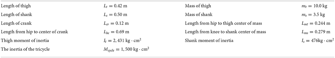
Table 1. Parameters of the rider-tricycle model (Einar et al., 2010).
The above equations can be solved based on the parameters provided at Table 1. Hence, the expression for angles θh and θs can be expressed by θ to reduce the degree-of-freedoms and dimensions of the rider-tricycle system.
Next, using the Euler-Lagrange equation, the inertia Mm(θ), centripetal-Coriolis C(θ), and gravitational effects Gm(θ) (right or left lag) are respectively expressed with respect to the crank angle as follows:
we obtain
Additionally, the passive viscous forces and external disturbance are applied as and d(t) = 0.1sin(0.25t), respectively. The desired crank position θd and velocity are designed as
Moreover, we define xd1 ≜ θd and , then we have
Next, the system (Equation 11) can be obtained. The initial conditions for the system are selected as x1 = 1 and x2 = 0. With the duration of FES, the time delay of muscle response will be increasing. Thus, the motor and muscle input delay are assumed as τe = 5 ms and ms. We obtain ck = 0.00625 and ms. Choosing the Lyapunov functions and , we obtain μ ≥ 1.
Given ke = 2, km = 2|sin(x1)|, c1 = 0.05, c2 = 0.1, c3 = 0.15, , , aσ(t) = 1, , and μ = 1.1, we derive λ = 55, ta = 0.19s, and Krσ(t) = 7I.
For comparison, the simulations are completed using the nominal system (without input delay and external disturbance) and time-varying input delays, which range from 1.7 to 250 ms. Results in Figure 2 depict the tracking trajectories of the nominal system and time delay system. Results in Figure 3 depict the tracking errors of nominal and time delay systems. It shows that, as the input delay is increasing, the proposed controller can ensure the boundedness of the tracking errors. The cadence error reaches 5% (0.261799rad/s) for the first time at 120.9 s. Whereafter, the assist mode is activated. The maximum cadence error of the delay system is 7.3% (0.3841rad/s). Correspondingly, the maximum cadence error of the nominal system is 3.8% (0.1998rad/s), as the cadence reaches 80% of the expected working aim. The results in Figure 4 depict the switching signals of the nominal and time delay systems. At the beginning of the simulation, the system is not switched to the FES subsystem until the cadence reaches 80% of the ideal cadence.
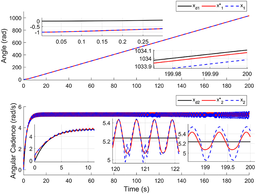
Figure 2. The tracking performance for nominal system and time delays system. The black solid lines (xd1, xd2), the red solid lines (), and the blue dotted lines (x1, x2) represent the trajectories of target, nominal system, and time delay system, respectively.
Figure 3. The tracking errors for nominal system and time delays system. The red solid lines () and the blue dotted lines (r1, r2) represent the tracking errors of the nominal and time delay systems, respectively.
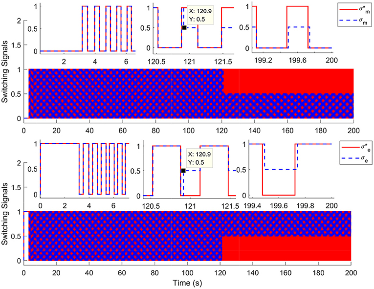
Figure 4. The switching signals for nominal system and time delays system. The red solid lines () and the blue dotted lines (σm, σe) represent the switching signals of the nominal and time delay systems, respectively.
In this paper, a model for FES-cycling with motor driven assistance is presented, which contains the effects of time-varying input delay and unknown disturbances. The input-to-state stability of the switched nonlinear FES-cycling system with time delays and disturbances has been analyzed. The state-dependent switching laws are considered for the switched nonlinear rider-tricycle system. Moreover, the property of ADT switching is introduced to avoid the frequent switching and chattering of subsystems. Novel ISS criteria have been derived by constructing an appropriate Lyapunov-Krasovskii functional under the ADT constraint. Compared with the existing results, the input delay in this paper is not assumed to be known but only requires its upper bound. Simulation results indicate the performance of the controller over a scope of time-varying input delays and the robustness to time-varying input delays up to 250 ms. In future work, the master-slave synchronous control for FES-cycling with electromechanical delays is an interesting topic (Liu et al., 2022; Shi et al., 2022).
The original contributions presented in the study are included in the article/supplementary material, further inquiries can be directed to the corresponding author/s.
YZ provides substantial contributions to the conception or design of the work and approval for publication of the content. XT drafts the work critically for important intellectual content. Both authors contributed to the article and approved the submitted version.
This work was supported in part by the National Natural Science Foundation of China (under Grant Nos. 62222310 and 61973131) and in part by the Fujian Outstanding Youth Science Fund under Grant No. 2020J06022.
The content of this manuscript has been presented in part at the Eighth International Conference on Control, Automation and Robotics (Tong and Zhu, 2022). Note that compared to the previous conference version, at least 30% of the content is original in this manuscript, such as the design of the state-feedback controller, and the simulation results used to verify the effectiveness of the proposed controller design approach. Therefore, this manuscript can be still considered as an original work.
The authors declare that the research was conducted in the absence of any commercial or financial relationships that could be construed as a potential conflict of interest.
All claims expressed in this article are solely those of the authors and do not necessarily represent those of their affiliated organizations, or those of the publisher, the editors and the reviewers. Any product that may be evaluated in this article, or claim that may be made by its manufacturer, is not guaranteed or endorsed by the publisher.
Alibeji, N., Kirsch, N., Farrokhi, S., and Sharma, N. (2015). Further results on predictor-based control of neuromuscular electrical stimulation. IEEE Trans. Neural Syst. Rehabil. Eng. 23, 1095–1105. doi: 10.1109/TNSRE.2015.2418735
Allen, B. C., Cousin, C. A., Rouse, C. A., and Dixon, W. E. (2022). Robust cadence tracking for switched FES-cycling with an unknown time-varying input delay. IEEE Trans. Control Syst. Technol. 30, 827–834. doi: 10.1109/TCST.2021.3070189
Bélanger, M., Stein, R. B., Wheeler, G. D., Gordon, T., and Leduc, B. (2000). Electrical stimulation: can it increase muscle strength and reverse osteopenia in spinal cord injured individuals? Arch. Phys. Med. Rehabil. 81, 1090–1098. doi: 10.1053/apmr.2000.7170
Burgess, K. E., Pearson, S. J., Breen, L., and Onambélé, G. N. (2009). Tendon structural and mechanical properties do not differ between genders in a healthy community-dwelling elderly population. J. Orthopaedic Res. 27, 820–825. doi: 10.1002/jor.20811
Cousin, C. A., Rouse, C. A., Duenas, V. H., and Dixon, W. E. (2019). Controlling the cadence and admittance of a functional electrical stimulation cycle. IEEE Trans. Neural Syst. Rehabil. Eng. 27, 1181–1192. doi: 10.1109/TNSRE.2019.2914579
Ding, J., Wexler, A., and Binder-Macleod, S. (2002). A predictive fatigue model-i: Predicting the effect of stimulation frequency and pattern on fatigue. IEEE Trans. Neural Syst. Rehabil. Eng. 10, 48–58. doi: 10.1109/TNSRE.2002.1021586
Downey, R. J., Merad, M., Gonzalez, E. J., and Dixon, W. E. (2017). The time-varying nature of electromechanical delay and muscle control effectiveness in response to stimulation-induced fatigue. IEEE Trans. Neural Syst. Rehabil. Eng. 25, 1397–1408. doi: 10.1109/TNSRE.2016.2626471
Einar, S. I. (2002). Development of a mathematical model of a rider-tricycle system. Technical report, Department of Engineering Cybernetics, NTNU, 1–7.
Einar, S. I., Ta, J., and Kenneth, J. H. (2004). “Finding the metabolically optimal stimulation pattern for FES-cycling,” in Proceedings of Conference of the International Functional Electrical Stimulation Society (Bournemouth, UK).
Einar, S. I., Tor, A. J., and Kenneth, H. (2010). A simplified nonlinear biomechanical model for FES-cycling. Technical report, Department of Engineering Cybernetics, NTNU, 1–4.
Ha, K. H., Murray, S. A., and Goldfarb, M. (2016). An approach for the cooperative control of FES with a powered exoskeleton during level walking for persons with paraplegia. IEEE Trans. Neural Syst. Rehabil. Eng. 24, 455–466. doi: 10.1109/TNSRE.2015.2421052
Hooker, S., Figoni, S., Rodgers, M., Glaser, R., Mathews, T., Suryaprasad, A., et al. (1992). Physiologic effects of electrical stimulation leg cycle exercise training in spinal cord injured persons. Arch. Phys. Med. Rehabil. 73, 470–476.
Iasson, K., Michael, M., Marcio, D. Q., Miroslav, K., and Ruzhou, Y. (2013). Predictor-based tracking for neuromuscular electrical stimulation. Int. J. Robust Nonlinear Control 25, 2391–2419. doi: 10.1002/rnc.3211
Jezernik, S., Wassink, R., and Keller, T. (2004). Sliding mode closed-loop control of FES: controlling the shank movement. IEEE Trans. Biomed. Eng. 51, 263–272. doi: 10.1109/TBME.2003.820393
Kei, M., Albert, H. V., Noritaka, K., and Milos, R. P. (2008). Neuromusculoskeletal torque-generation process has a large destabilizing effect on the control mechanism of quiet standing. J. Neurophysiol. 100, 1465–1475. doi: 10.1152/jn.00801.2007
Laura, A. K., Elke, S., Catherine, D.-K., and Hermie, J. H. (2007). Myoelectric manifestations of fatigue at low contraction levels in subjects with and without chronic pain. J. Electromyogr. Kinesiol. 17, 264–274. doi: 10.1016/j.jelekin.2006.04.004
Liu, Z., Lin, W., Yu, X., Rodríguez-Andina, J. J., and Gao, H. (2022). Approximation-free robust synchronization control for dual-linear-motors-driven systems with uncertainties and disturbances. IEEE Trans. Ind. Electron. 69, 10500–10509. doi: 10.1109/TIE.2021.3137619
Merad, M., Downey, R. J., Obuz, S., and Dixon, W. E. (2016). Isometric torque control for neuromuscular electrical stimulation with time-varying input delay. IEEE Trans. Control Syst. Technol. 24, 971–978. doi: 10.1109/TCST.2015.2470637
Mohr, T., Pødenphant, J., Biering-Sørensen, F., Galbo, H., Thamsborg, G., and Kjaer, M. (1997). Increased bone mineral density after prolonged electrically induced cycle training of paralyzed limbs in spinal cord injured man. Calcif Tissue Int. 61, 22–25. doi: 10.1007/s002239900286
Obuz, S., Duenas, V. H., Downey, R. J., Klotz, J. R., and Dixon, W. E. (2020). Closed-loop neuromuscular electrical stimulation method provides robustness to unknown time-varying input delay in muscle dynamics. IEEE Trans. Control Syst. Technol. 28, 2482–2489. doi: 10.1109/TCST.2019.2926945
Petrofsky, J. (2003). New algorithm to control a cycle ergometer using electrical stimulation. Med. Biol. Eng. Comput. 41, 18–27. doi: 10.1007/BF02343534
Sharma, N., Gregory, C. M., and Dixon, W. E. (2011). Predictor-based compensation for electromechanical delay during neuromuscular electrical stimulation. IEEE Trans. Neural Syst. Rehabil. Eng. 19, 601–611. doi: 10.1109/TNSRE.2011.2166405
Shi, P., Sun, W., Yang, X., Rudas, I., and Gao, H. (2022). Master-slave synchronous control of dual drive gantry stage with cogging force compensation. IEEE Trans. Syst. Man Cybern. Syst. 1–10. doi: 10.1109/TSMC.2022.3176952
Tong, X., and Zhu, Y. (2022). “Stability analysis for switched functional electrical stimulation cycling with unknown time-varying input delays,” in 2022 8th International Conference on Control, Automation and Robotics (ICCAR) (Xiamen), 127–132.
Wang, Y.-E., Sun, X.-M., Wang, Z., and Zhao, J. (2014). Construction of Lyapunov-Krasovskii functionals for switched nonlinear systems with input delay. Automatica 50, 1249–1253. doi: 10.1016/j.automatica.2014.02.029
Keywords: functional electrical stimulation, Lyapunov-Krasovskii functional, rehabilitation robotics, switched nonlinear system, time-varying input delay
Citation: Tong X and Zhu Y (2022) Robust tracking for functional electrical stimulation cycling with unknown time-varying input delays: A switched systems approach. Front. Neurorobot. 16:1022839. doi: 10.3389/fnbot.2022.1022839
Received: 19 August 2022; Accepted: 12 September 2022;
Published: 20 October 2022.
Edited by:
Ning Sun, Nankai University, ChinaReviewed by:
Wei Sun, Liaocheng University, ChinaCopyright © 2022 Tong and Zhu. This is an open-access article distributed under the terms of the Creative Commons Attribution License (CC BY). The use, distribution or reproduction in other forums is permitted, provided the original author(s) and the copyright owner(s) are credited and that the original publication in this journal is cited, in accordance with accepted academic practice. No use, distribution or reproduction is permitted which does not comply with these terms.
*Correspondence: Yanzheng Zhu, eWFuemhlbmd6aHVAc2R1c3QuZWR1LmNu
Disclaimer: All claims expressed in this article are solely those of the authors and do not necessarily represent those of their affiliated organizations, or those of the publisher, the editors and the reviewers. Any product that may be evaluated in this article or claim that may be made by its manufacturer is not guaranteed or endorsed by the publisher.
Research integrity at Frontiers
Learn more about the work of our research integrity team to safeguard the quality of each article we publish.