 Ricardo Martín Abraham-Ekeroth
- 1Instituto de Física Arroyo Seco, IFAS (UNCPBA), Tandil, Argentina
- 2Grupo de Plasmas Densos, CIFICEN (UNCPBA-CICPBACONICET), Tandil, Argentina
Introduction: The formation of a stable magneto plasmonic dimer with THz resonances is theoretically studied for the principal directions of the system. Unlike a recent report, our work provides a complete description of the full photonic coupling for arbitrary magnetic fields as, for instance, unbalanced particle spins.
Methods: As an illustration, we consider two small, n-doped InSb nanoparticles under illumination by two counter-propagating plane waves.
Results: Remarkably, when an external magnetic field exists, the symmetry in the system is broken, and a resonant radiation pressure for the dimer appears. Similarly, tunable inter-particle forces and spins are exerted on the non-reciprocal dimer. The system is also characterized when the magnetic field is absent. Moreover, we show how the mechanical observables truly characterize the dimer since their resonance dependency contains detailed information about the system.
Discussion: Unlike far-field observables like absorption, mechanical magnitudes depend on the system's near-field. In addition, the nature of the particle spins is originally explained by the energy flow's behavior around the dimer. This work constitutes a generalization of any previous approach to optical binding between small nanoparticles. It paves the way for fully controlling optical matter and nano factory designs based on surface plasmon polaritons.
1 Introduction
Optical matter (OM) consists of arrays of micro or nanoparticles that are somehow bound and controlled by light (Burns et al., 1990). An OM able to self-assemble at will to develop solid technology is a long-standing goal in photonics (Parker et al., 2020). The background for OM is the particle manipulation by optical forces; the first results were applied to microparticles due to the lack of technology and the presence of thermal noise for smaller systems (Ashkin and Dziedzic, 1975; Ashkin and Dziedzic, 1989). Generally, OM comprises multiple particles subjected to electromagnetic forces that come from their mutually scattered light. However, this multiple scattering phenomena can be very complex and bring about unusual effects such as “non-reciprocal” forces, torque opposite to the illumination angular momentum, and non-conservative forces (Albaladejo et al., 2009; Parker et al., 2020). Appropriate control of OM by forces and torques could lead to programmable materials for optomechanical, rheological, and biological applications. In this respect, many works studied the optical binding between nanoparticles as a primary tool to develop OM. Some approached specific combinations of optical beams like those with programmable phase (Han et al., 2018; Nan et al., 2022). For example, light-induced rotation of objects holds potential for various applications such as sensing, cargo transportation, drug delivery, and micro/nanosurgery (Arita et al., 2020; Blázquez-Castro et al., 2020; Xin et al., 2020). Optical traps use the combination of beams as a potent characterization tool for material science and biophysics, as in Ref. (Erdogan et al., 2022), which uses electrostatic focusing to obtain the mass spectrum of SARS-CoV-2 and BoHV-1 virions. However, the high intensity at the focal spot may introduce laser heating, which is an issue for bio applications (Nan et al., 2022).
On the other hand, recent advances in THz technology call for new devices and materials that exhibit a non-reciprocal behavior for photonic networks and optical information processing (Shui et al., 2022). Non-reciprocal devices are a crucial component of modern communication technology. They are nowadays required for miniaturized electronic and photonic devices (Nature, 2020). One way to create optical non-reciprocity at the THz range is using magneto-optical (MO) systems like graphene, hexaferrites, and semiconductors (Kimel et al., 2022). For instance, Ref (Chochol et al., 2016). presented MO measurement of several samples of InSb with different carriers and carrier concentrations for low external magnetic field and room temperatures. With these advantages, dimers and trimers of InSb particles have been studied to enhance THz spectroscopy by forming electric and magnetic hotspots in the gap between them (Bakker et al., 2015; Sadrara and Miri, 2019). Anisotropic materials like InSb in OM would make it strongly dependent on the beam combinations, allowing for countless possibilities (Roichman et al., 2008). Recently, several efforts have focused on MO nanoparticle systems to shape OM and optical traps with a reasonable degree of control and accuracy, besides other relevant applications (Emile et al., 1992; Hu et al., 2013; Abraham Ekeroth et al., 2017; Edelstein et al., 2019; Edelstein et al., 2022). On a broader sense, magnetoplasmonics relates the plasmonic behavior of nanoparticles with the presence of external magnetic fields. The modulation and tunability of plasmonic resonances offered by magnetoplasmonics results auspicious for ultra-sensitive sensors and active plasmonic devices (Lacroix et al., 2012). In particular, the formation of stable optical binding between two small magnetoplasmonic particles has been lately studied (Edelstein et al., 2021). Equilibrium binding distances were predicted and found tunable by the incoming wave’s polarization state and the magnetic field’s magnitude. However, the model developed in that report is valid only for relatively small magnetic field values. Moreover, it predicts stable dimers only using alternating magnetic static fields and polarization angles to remove azimuthal, unbalanced forces. More importantly, that work needs to discuss possible rotations of the particles due to angular momentum transfer in the multiple scattering scheme.
In this paper, we study the formation of stable MO dimers for small nanoparticles in a complete framework involving all the possible optomechanical inductions. The dimer’s isotropic and anisotropic responses are assessed as a base for OM designs, i.e., under the presence/absence of an external magnetic field. This field can be of arbitrary magnitude in our model. The illumination consists of two counter-propagating plane waves with circular polarization, which simulates a simple optical trap in the vacuum. We found several possibilities to create stable dimers when the magnetic field is on. The beams do not exert net forces for reciprocal dimers but may exert torques on them. Nonetheless, there is a net radiation pressure and spin for the whole system when the static field is on, allowing complete control of the system’s movement. The results will enable one to infer that the mechanical variables can be used as near-field observables to explore the content of unknown samples. Conversely, they can be used to accurately control the dimer’s creation/destruction and its mobility. Finally, the spins predicted are explained in terms of the energy flows around the dimer, which constitutes a novel scattering-force effect for interacting particle arrays.
2 Model
In the following, we assume two equal particles of the same non-reciprocal material immersed in the vacuum. In particular, we simulate nanoparticles made of n-doped Indium antimonide (n-InSb) (Palik et al., 1976) when a static magnetic field is along the z-direction,
where
Here, ϵ∞ is the high-frequency dielectric constant, ωL is the longitudinal optical phonon frequency, ωT is the transverse optical phonon frequency,
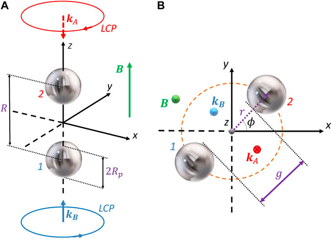
FIGURE 1. (Color online) Dimer configurations and incident waves treated in this work. Two counter-propagating waves with left circular polarization illuminate the magneto-optical dimer. The leading example consists of two n-doped InSb particles separated by a gap of a particle’s diameter, g = 2Rp. (A) Parallel [(B) perperdicular] configuration. The static magnetic field B is parallel to +z direction (green arrow). In (B), ϕ is the azimuthal angle of the dimer’s position from x.
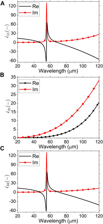
FIGURE 2. (Color online) Spectra of components for the permittivity tensor given in Eq. 1 for B = 1 T. (A)
For two small particles compared to the wavelength, we can make use of the approximation of discrete dipoles (Discrete Dipole Approximation, DDA) (Draine and Flatau, 1994; de Sousa et al., 2016). The usual DDA approximates a continuum system by a finite array of polarizable cells, thus constituting a non-relativistic integral solution of Maxwell equations. The cells acquire dipole moments in response to the local fields. These dipoles interact with one another via the appropriate Green functions (Novotny and Hecht, 2006). Then, proper cell polarizabilities can consider multiple-scattering scenarios. The principal limitation of the DDA concerns the handling of particle boundaries and interparticle distances since the geometry’s representation of the array has a minimum length scale equal to the inter-dipole spacing (Draine and Flatau, 1994; Yurkin and Hoekstra, 2007). Following the general criteria (Draine and Flatau, 1994), we represent the particles by dipoles, provided they are much smaller than the wavelengths under study. Similarly, we deal with inter-particle gaps relatively large enough to model a dimer with two dipoles. In such a case, the DDA simplifies considerably to
where
where
being V the particles’ volume,
where R = r − r′, R = |r − r′|, and ⊗ denotes the exterior product (Novotny and Hecht, 2006). In particular,
where we define
This field is used in Eq. 8 to calculate the incident field at the particles’ positions E0,1 and E0,2.
The absorption cross section of the system can be calculated once the dipole moments are known by
where
where the derivatives of the total field
The total force exerted on the dimer results from adding the force components for each particle, namely, Ftot,i = F1,i + F2,i. In particular, the net radiation pressure for the dimer under the illumination given by Eq. 10 is defined by taking i = 3, or the z components, as
Another useful mechanical variable is the binding force, which in the present case is defined as
where
where
The definitions of the orbital and spin torques were discussed previously in Refs. (Chaumet and Rahmani, 2009; Nieto-Vesperinas, 2015a; Nieto-Vesperinas, 2015b), among others. The spin torques are always defined with respect to the centers of the particles. Otherwise, the reference system is located at the dimer’s center of mass, and orbital torques are set. Thus, the total torque exerted on the dimer is
Since we are interested in the near-field interactions between the particles, the study focuses on an example for which the interparticle’s gap equals one particle diameter (g = 2Rp); see Figure 1. We add complementary examples for other values of g in the Supplementary Material (SM).
3 Results
In this section, all the optical variables were scaled by the proper factors to make them dimensionless. The following characteristic magnitudes, namely,
are approximately fulfilled in our model (Dholakia and Zemánek, 2010). Here, x = k0R and we define two more dimensionless numbers, i.e.,
3.1 Parallel illumination
Figure 3 shows the spectral results for parallel illumination when the magnetic field is off (B = 0, black line) and on (B = 1 T, red line with squares). The absorption efficiencies, Figure 3A, result independent of the direction of the dimer so that the same spectra remain for any other illumination configuration. The low-energy resonance (around 73 μm) corresponds to an SPP, while the high-energy resonance (48.7 μm) corresponds to an SPhP (Palik et al., 1976; Moncada-Villa et al., 2015). Making use of the Plasmon Hybridization Model (PHM) for two dipolar particles, both kinds of surface modes show as bright antibonding modes for transverse electric fields according to the configuration shown in Figure 1A, see Ref (Nordlander et al., 2004) for details.
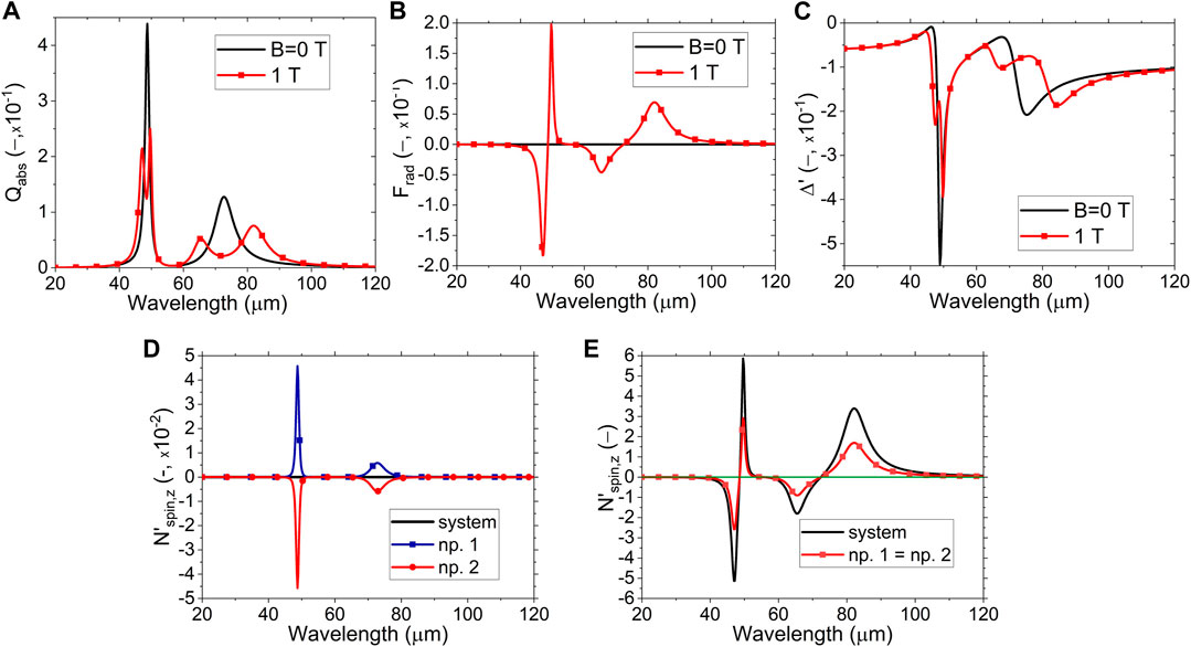
FIGURE 3. (Color online) Optical properties for parallel configuration. (A) Absorption efficiency, which is independent of the dimer’s orientation. (B) Radiation pressure (total force along z). (C) Binding force. Black line [red line with squares] for magnetic field B = 0 [B = 1] T. (D, E) Spin torques for B = 0 [B = 1] T. In (D), the net spin torque is zero for all wavelengths.
When B is on, each isotropic surface mode splits into two modes due to degeneracy removal. The absorption is the only far-field observable shown in this work since negligible scattering occurs for small systems (Bohren and Huffman, 1998). As it is illumination-independent, the spectra obtained remain invariant for all illumination directions concerning the dimer’s axis. Thus, the only available far-field observable is neither adequate to study the interactions occurring in the dimer nor valuable to predict the dimer’s dynamics. In Figure 3B, there is no net radiation pressure when B is off due to the high symmetry of both the system and incident field. On the other hand, there is a resonant pressure for the MO dimer when B is on, revealing the magnetoplasmonic resonances and directing the dimer upwards or downwards according to their energy. As a result of the interaction, the radiation pressure identifies the modes by the sign of the force. Figure 3C shows that the binding force leads to repulsion between the particles for both cases, B = 0 and B = 1 T. In other words, there cannot be a stable dimer under this parallel configuration. The response is still resonant but less sensitive than the radiation pressure. Remarkably, the results agree with the interpretation given by the PHM.
Notably, although we are dealing with a dimer system, our results agree with those reported in (Edelstein et al., 2019) for a single particle under the same illumination. In general, the absorption efficiency Qabs behaves like Re{α11}, both the radiation pressure Frad and the spin
Following angular momentum’s conservation, Figure 3D shows that the net spin for the system is zero when B is off (black line). To put it another way, the spins for each particle are equal and opposite, showing the resonant modes for the isotropic case (see red and blue lines with symbols). When B is on, however (Figure 3E), there is a net spin for the system, black line, which is twice the spin for each particle (red line with squares). The spin resonates sensitively with the dimer’s modes, quite like the radiation pressure. Consequently, the spins become much stronger than those for B off, compare the scales of Figures 3D, E. Thus, the radiation pressure and spins constitute the most sensitive observables in the near field, giving a common spectral shape (compare spectra in Figures 3B, E).
3.2 Perpendicular illumination
Now we vary the dimer’s azimuthal angle since a dependency on the net polarization is expected. ϕ is defined as the angle from the x-axis in Figure 1, but it could be defined as the angle between the dimer’s axis and the incident electric field, which is driven by the phase offset between the incident waves.
Figures 4, 5 show maps as a function of the incident wavelength and azimuthal angle for B = 0 and B = 1 T, respectively. Similarly to that found in the previous subsection, there is no net radiation pressure when B is off (not shown). Yet this time, a different behavior for the binding force is found, Figure 4A. The system offers a resonant spectral response but depends on the angle ϕ. Maxima [minima] of binding are found around ϕ = 90, 270 [ϕ = 0, 180] deg, meaning inter-particle attraction [repulsion]. The tangential force has its zeros where Δ′ gets its extremes; Figure 4B. This phenomenon indicates no stable dimers in the spectra studied. In particular, the unstable dimer positions around the strongest optical resonance, namely, the SPhP at 48.7μm, can be found at ϕ = 34, 145.6, 214.5, 325.7 deg for all wavelengths when B is off (follow the black lines in Figure 4A). A similar situation is found for the second resonant wavelength
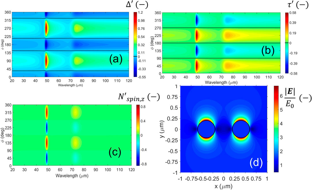
FIGURE 4. (Color online) Near-field observables for perpendicular configuration in the absence of magnetic field, B = 0 T. (A–C) Maps of the mechanical variables as a function of wavelength and dimer’s azimuthal angle. (A, B) Binding [tangential] force. The black lines correspond to zero forces. (C) Spin torque for the system. In this case, the net radiation pressure is zero for all wavelengths (not shown). (D) Distribution of electric field around the dimer for z = 0 at the resonance wavelength 48.85 μm for ϕ = 0.
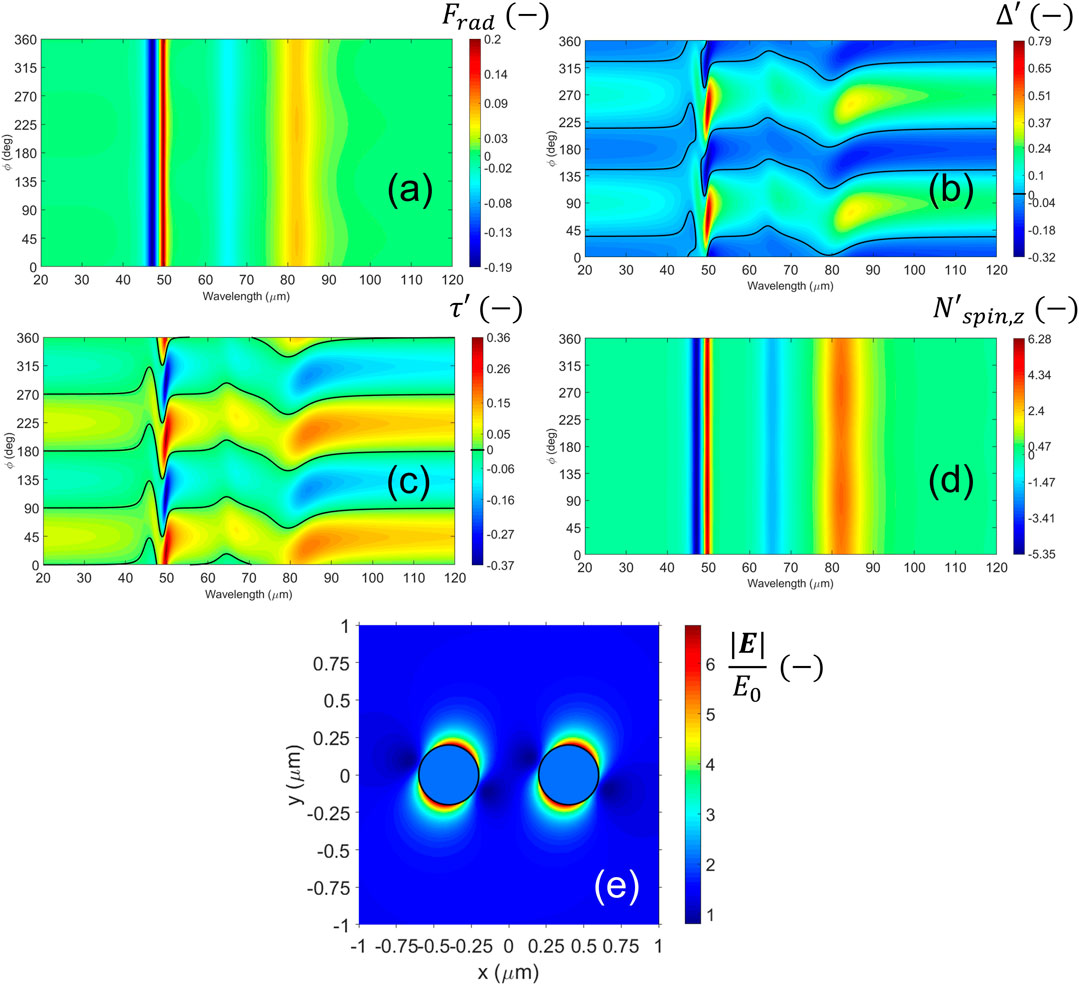
FIGURE 5. (Color online) Near-field observables for perpendicular configuration and B = 1 T. (A–D) Maps of the mechanical variables as a function of wavelength and dimer’s azimuthal angle. (A) Radiation pressure for the system. (B, C) Binding [tangential] force. The black lines correspond to zero force. (D) Spin torque for the system. (E) Distribution of electric field around the dimer for z = 0 at the resonant wavelength 49.85 μm for ϕ = 0.
Noteworthy, our results are consistent with the interpretation of the PHM for isotropic, dipolar particles (Nordlander et al., 2004). In particular, each value ϕ = nπ [ϕ = (n + 1/2)π] rad with
In Figure 5A, there is a remaining radiation pressure for the whole system due to the symmetry breaking that appears only at the resonances’ locations. This spectrum results invariant with ϕ and follows the same resonances as in absorption in Figure 3A when B is on (red line with squares). Thus the presence of a static magnetic field induces the dimer to move forward or backward in the illumination’s direction when the incident energy is that of a surface mode. Likewise, the system shows resonant binding and tangential forces (Figures 5B, C). As in Figures 4A, B, the black lines follow the values of zero force. Note that the map strongly distorts by the presence of the resonances when B is on, making the dynamics more complex and even reducing the extremals of the binding force. However, stable binding could be possible around the SPhP due to the overlapping of MO modes, which means more degree of control in the dimer’s creation and stability. In the maps of Figures 5A–C, there are some small overlapping regions where all the forces are equal to zero. The possibility to obtain stable dimers is discussed in more detail in Section 3.4.
In Figure 5D, the system’s spin follows a trend similar to that for the radiation pressure in Figure 5A. This behavior is quite different from that found for B = 0. Note that spin is enhanced when B is on; the colorbar limits show values
Figure 5E shows the electric field around the dimer’s plane z = 0 for the SPhP found at 49.85 μm. This wavelength corresponds to the most robust resonance when B is on. The rest of the configuration is equal to that given in Figure 4D. The field hot spots are leaned on the right
Up to this point, we have explored a few examples of MO dimers to approach the idea of controlling the particle dynamics and “photonic molecule” stability (Hong et al., 2013) in the presence/absence of a static magnetic field B.
Below, we discuss the behavior of the dynamic observables in terms of the information contained in the Poynting field. The reader is reminded that the particles’ photonic interaction matches a multiple-scattering framework (Mishchenko et al., 2006; Conoir, 2007). The near fields involve the evanescent waves, which play a crucial role in the particles’ interaction for surface modes and close particles. This phenomenon can be seen through the energy flows because they may have all the information of the near fields E and H. Generally, the magnitudes obtained from far-field calculations lose some of the information about the system (Novotny and Hecht, 2006).
3.3 Nature of the spins through an examination of the poynting fields
We explore the spins exerted on the system by showing a few calculations of the Poynting field around the dimer for perpendicular configuration. The parallel configuration is less interesting since it would only lead to repulsion states without dimer formation for any gap under both cases B = 0 and 1 T, see Figure 3C for the example g = 2R. More clarifications can be found in the SM.
Figures 6A–F consist of maps related to the energy flow when B is off [on] upon different azimuthal angles. The wavelengths coincide with that for the strongest SPhP in each case. The left column (a-c-e) shows the Poynting field S when z = 0. Similarly, the right column (b-d-f) shows the z-component of ∇ ×S. The white arrows are rescaled to visualize the maps easily. Interestingly, Figures 6A, B show an example of a repulsion state with zero spins when ϕ = 0, see Figures 4A–C. Even though S aligns in a single direction, a resonant magnitude and a non-negligible curl appear near the surface of the particles. This resonance is due to the excitation of the SPhP. However, the contributions to the spin cancel out due to high symmetry evidenced by these maps and zero net spin results for the system; Figures 6C, D show the attraction state with maximum positive spin when ϕ = 135 deg, see Figures 4A–C. This time, two hot spots of maximum magnitude face each other, and a kind of saddle point emerges in the gap region between the particles; Figure 6C. As a result, the values of the curl clearly show a rotational state for light as the field spots have “turbine-blade” shapes; Figure 6D, explaining the net positive spin calculated for the system in Figure 4C for ϕ = 135 deg. It is also evident from Figure 6D that the two particles have the same spin, visually showing that the net spin is two times the spin of one particle. Finally, we show the example when B is on and ϕ = 67.2 deg, which coincides with the hot spot of maximum attraction at the resonance 49.85 μm of the SPhP, see Figure 5B. Notice in passing that this value for ϕ is close to the angle of the electric spots in Figure 5E, namely,
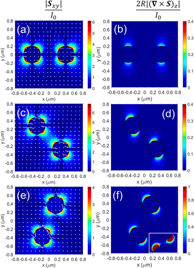
FIGURE 6. (Color online) Scaled energy flows around the dimer for z = 0 under perpendicular configuration and at the strongest SPhP. The color scale corresponds to the magnitude; the white arrows show the Poynting flow. Left [right] column for the [z-component of the curl of the] Poynting field. (A–F) Examples for B = 0 [B = 1] T; the wavelength is 48.85 μm [49.85 μm]. (A,B) For ϕ = 0 deg, (C,D) ϕ = 135 deg, and (E,F) 67.2 deg. The inset in (F) zooms the gap region up to a maximum of 0.05 in the colorbar. The arrows in (A,C,E) are respectively 1, 2.2, and 3 times their original size.
3.4 About dimers’ stability
We anticipated in Section 3.2 that special dimer configurations could lead to stable or “pseudo-stable” dimers only when B is on. For example, Δ′ = 0,
For the spectral ranges covered, a few stable states can be found by exploring the maps in Figure 5 and the derivatives of the force functions. For example, Figure 7 shows results for a wavelength 43.8 μm, assuming that Δ′ ≈ 0, τ′ = 0, Frad ≈ 0, and
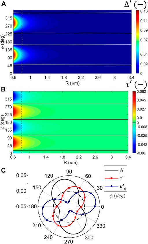
FIGURE 7. (Color online) The binding and tangential forces are varied under perpendicular configuration and B = 1 T to study the dimers’ stability: example at 43.8 μm. (A, B) Maps as a function of the center-to-center distance (R) and ϕ; solid lines indicate zero force. (A) Binding and (B) tangential force. Vertical dashed lines correspond to R = 4Rp (or g = 2Rp). (C) Polar plot for the case g = 2Rp. The circle in the dashed line indicates the true zero force. The solid black line corresponds to binding, red with squares to tangential force, and blue with circles to the spring-constant
Note that the binding and tangential forces do not change for relatively large distances in the near field, Figures 7A, B; in fact, they start to vary for values close to R = 0.6 μm, which is not our leading example. These almost constant zero-force lines indicate that
One may wonder about the relation between the far-fields and net radiation pressure exerted on the dimer when B is on. When B is off, and for small systems, the far-field scattering pattern is the well-known doughnut shape of a short dipolar antenna (R/λ < 0.1), which spreads the electric field in all directions but that of the net system’s dipole (Novotny and Hecht, 2006; Stratton, 2007). The dipole’s direction would be the electric field’s in the near-field, which in our case is along the y-direction, see Figure 4D. When B is on, this 3D pattern rotates a certain angle around the z-axis from the x-axis (not shown here). For the example at the wavelength 49.85 μm, this angle is 65 deg., in agreement with the result of Figure 5E. Ref (Abraham Ekeroth, 2018). studied the relation between the far-field scattering patterns and the optomechanical magnitudes for dimers of plasmonic cylinders. For small systems, the scattering patterns were not distorted from those of the dipoles, and their emission direction was that transversal to the incident polarization. For bigger systems, i.e., beyond the dipolar approximation, a connection between net forces and bent patterns was found. In this work, we checked that conclusion for MO small systems when B is on; there is no distortion of the far-field patterns that could explain net forces exerted on the dimer. Thus, the origin of this force must be connected with the near fields.
4 Conclusion
By a simple dipolar model, this work explores the behavior of small nanoparticle dimers when magneto-optical materials like n-doped InSb and moderate magnetic fields are used. Two counter-propagating waves with equal circular polarization are used as illumination to simulate a simple optical trap with neither net gradient nor scattering forces. Our results show that the system can be thoroughly characterized by observing its mechanical inductions, provided these latter depend on the near field. Besides, we found no stable dimers when the dimer is aligned with the illumination since the inter-particle force only leads to repulsion. On the contrary, under “perpendicular” alignment and in the presence of a magnetic field, we found dimer’s stability is possible, at least under this “static” model for which the particles’ velocities and accelerations are not considered. As the results strongly depend on the magnetic field’s presence, this study constitutes a novel background to build OM or photonic molecule nano factories and control their movements, or conversely, to study samples containing this class of multimers.
Finally, we give an original explanation for the appearance of particle spins based on the energy flows. This interpretation offers satisfactory results from the “scattering” forces produced by the interaction between the particles. Gradient forces were also investigated but showed no appreciable influence on the spins’ appearances (results not shown in this work).
It is worth mentioning that there is a compromise between the particle size and inter-particle gap to maintain the maps in Figures 4, 5 “invariant” or scalable. In the region between Rp = 0.05 and 0.65 μm for a condition g = 2Rp, or when Rp = 0.2 μm for gaps above g = 0.1Rp, very similar maps to those reported in Figures 4, 5 are obtained. There are only variations in the relative colormap intensities. As particle sizes increase compared to g, some hotspots that appear at special values of ϕ start to accentuate or deform. The shapes start distorting more from particle radii Rp≅0.7 μm and beyond, or for interparticle gaps shorter than g = 0.1Rp when Rp ∼ 0.2 μm. Remarkably, the maps for Δ′ may provide newer “zero” lines according to the distortions. However, when one increases g and fixes the particles’ size, the original shapes are recovered. Thus, we can state a “rule of thumb”: our results apply to nanoparticle dimers with particle sizes between 0.1 and 1.4 μm as long as g remains in the order or larger than Rp. For other lengths, the model presented in Section 2 still works but the maps would change their shape. Nonetheless, smaller particles or tiny gaps may require a size or non-local correction to the dielectric tensor of the system to recover realistic results (García de Abajo, 2008; Scaffardi et al., 2013). This work provides a few examples to illustrate the general model. Exhaustive studies about the parametric variations of geometry or particle constitution are considered beyond the scope of this paper.
Data availability statement
The raw data supporting the conclusion of this article will be made available by the authors, without undue reservation.
Author contributions
The author confirms being the sole contributor of this work and has approved it for publication.
Acknowledgments
The author would like to thank A. García-Martín from IMN-CSIC and M.I. Marqués from Universidad Autónoma de Madrid for their valuable discussions during his postdoc in Spain. The author would also like to thank the reviewers for taking the time and effort to review the manuscript. All their valuable comments helped significantly improve the manuscript’s quality.
Conflict of interest
The author declares that the research was conducted in the absence of any commercial or financial relationships that could be construed as a potential conflict of interest.
Publisher’s note
All claims expressed in this article are solely those of the authors and do not necessarily represent those of their affiliated organizations, or those of the publisher, the editors and the reviewers. Any product that may be evaluated in this article, or claim that may be made by its manufacturer, is not guaranteed or endorsed by the publisher.
Supplementary material
The Supplementary Material for this article can be found online at: https://www.frontiersin.org/articles/10.3389/fnano.2023.1134850/full#supplementary-material
References
Abraham Ekeroth, R. M., García-Martín, A., and Cuevas, J. C. (2017). Thermal discrete dipole approximation for the description of thermal emission and radiative heat transfer of magneto-optical systems. Phys. Rev. B 95, 235428. doi:10.1103/PhysRevB.95.235428
Abraham Ekeroth, R. M. (2018). New characterization of plasmons in nanowire dimers by optical forces and torques. Plasmonics 13, 1817–1831. doi:10.1007/s11468-018-0696-4
Abraham-Ekeroth, R. M. (2022). Enhanced deep-tissue photoacoustics by using microcomposites made of radiofrequency metamaterials and soft polymers: Double- and triple-resonance phenomena. J. Appl. Phys. 132, 083103. doi:10.1063/5.0086553
Albaladejo, S., Marqués, M. I., Laroche, M., and Sáenz, J. J. (2009). Scattering forces from the curl of the spin angular momentum of a light field. Phys. Rev. Lett. 102, 113602. doi:10.1103/PhysRevLett.102.113602
Arita, Y., Simpson, S. H., Zemánek, P., and Dholakia, K. (2020). Coherent oscillations of a levitated birefringent microsphere in vacuum driven by nonconservative rotation-translation coupling. Sci. Adv. 6, eaaz9858. doi:10.1126/sciadv.aaz9858
Ashkin, A., and Dziedzic, J. M. (1975). Optical levitation of liquid drops by radiation pressure. Science 187, 1073–1075. doi:10.1126/science.187.4181.1073
Ashkin, A., and Dziedzic, J. M. (1989). Internal cell manipulation using infrared laser traps. Proc. Natl. Acad. Sci. U. S. A. 86, 7914–7918. doi:10.1073/pnas.86.20.7914
Bakker, R. M., Permyakov, D., Yu, Y. F., Markovich, D., Paniagua-Domínguez, R., Gonzaga, L., et al. (2015). Magnetic and electric hotspots with silicon nanodimers. Nano Lett. 15, 2137–2142. doi:10.1021/acs.nanolett.5b00128
Blázquez-Castro, A., Fernández-Piqueras, J., and Santos, J. (2020). Genetic material manipulation and modification by optical trapping and nanosurgery-A perspective. Front. Bioeng. Biotechnol. 8, 580937. doi:10.3389/fbioe.2020.580937
Bohren, C. F., and Huffman, D. R. (1998). Absorption and scattering of light by small particles. edición: new edition edn. Weinheim: Wiley VCH.
Boriskina, S. V. (2013). “Plasmonics with a twist: Taming optical tornadoes on the nanoscale,” in Plasmonics: Theory and applications. Challenges and advances in computational chemistry and physics. Editors T. V. Shahbazyan, and M. I. Stockman (Dordrecht: Springer Netherlands), 431–461. doi:10.1007/978-94-007-7805-4_12
Burns, M. M., Fournier, J.-M., and Golovchenko, J. A. (1990). Optical matter: Crystallization and binding in intense optical fields. Science 249, 749–754. doi:10.1126/science.249.4970.749
Cameron, R. P., Barnett, S. M., and Yao, A. M. (2014). Optical helicity of interfering waves. J. Mod. Opt. 61, 25–31. doi:10.1080/09500340.2013.829874
Chaumet, P. C., and Billaudeau, C. (2007). Coupled dipole method to compute optical torque: Application to a micropropeller. J. Appl. Phys. 101, 023106. doi:10.1063/1.2409490
Chaumet, P. C., and Nieto-Vesperinas, M. (2000). Time-averaged total force on a dipolar sphere in an electromagnetic field. Opt. Lett. 25, 1065–1067. doi:10.1364/OL.25.001065
Chaumet, P. C., and Rahmani, A. (2009). Electromagnetic force and torque on magnetic and negative-index scatterers. Opt. Express 17, 2224–2234. doi:10.1364/OE.17.002224
Chochol, J., Postava, K., Čada, M., Vanwolleghem, M., Halagačka, L., Lampin, J.-F., et al. (2016). Magneto-optical properties of InSb for terahertz applications. AIP Adv. 6, 115021. doi:10.1063/1.4968178
Conoir, J.-M. (2007). Multiple scattering, interaction of time-harmonic waves with N obstacles. J. Acoust. Soc. Am. 121, 2473. doi:10.1121/1.2715667
de Sousa, N., Froufe-Pérez, L. S., Sáenz, J. J., and García-Martín, A. (2016). Magneto-optical activity in high index dielectric nanoantennas. Sci. Rep. 6, 30803. doi:10.1038/srep30803
Dholakia, K., and Zemánek, P. (2010). Colloquium: Gripped by light: Optical binding. Rev. Mod. Phys. 82, 1767–1791. doi:10.1103/RevModPhys.82.1767
Draine, B. T., and Flatau, P. J. (1994). Discrete-dipole approximation for scattering calculations. JOSA A 11, 1491–1499. doi:10.1364/JOSAA.11.001491
Edelstein, S., Abraham-Ekeroth, R. M., Serena, P. A., Sáenz, J. J., García-Martín, A., and Marqués, M. I. (2019). Magneto-optical Stern-Gerlach forces and nonreciprocal torques on small particles. Phys. Rev. Res. 1, 013005. doi:10.1103/PhysRevResearch.1.013005
Edelstein, S., García-Martín, A., Serena, P. A., and Marqués, M. I. (2021). Magneto-optical binding in the near field. Sci. Rep. 11, 20820. doi:10.1038/s41598-021-00217-6
Edelstein, S., Garcia-Martin, A., Serena, P. A., and Marqués, M. I. (2022). Circular dichroism in magneto-optical forces. Opt. Express 30, 28668. doi:10.1364/OE.464252
Ekeroth, R. M. A. (2019). Optical forces and torques exerted on coupled silica nanospheres: Novel contributions due to multiple scattering. J. Opt. 21, 045001. doi:10.1088/2040-8986/ab0533
Emile, O., Bardou, F., Salomon, C., Laurent, P., Nadir, A., and Clairon, A. (1992). Observation of a new magneto-optical trap. Europhys. Lett. 20, 687–691. doi:10.1209/0295-5075/20/8/004
Erdogan, R. T., Alkhaled, M., Kaynak, B. E., Alhmoud, H., Pisheh, H. S., Kelleci, M., et al. (2022). Atmospheric pressure mass spectrometry of single viruses and nanoparticles by nanoelectromechanical systems. ACS Nano 16, 3821–3833. doi:10.1021/acsnano.1c08423
García de Abajo, F. J. (2008). Nonlocal effects in the plasmons of strongly interacting nanoparticles, dimers, and waveguides. J. Phys. Chem. C 112, 17983–17987. doi:10.1021/jp807345h
Haefner, D., Sukhov, S., and Dogariu, A. (2009). Conservative and nonconservative torques in optical binding. Phys. Rev. Lett. 103, 173602. doi:10.1103/PhysRevLett.103.173602
Han, F., Parker, J. A., Yifat, Y., Peterson, C., Gray, S. K., Scherer, N. F., et al. (2018). Crossover from positive to negative optical torque in mesoscale optical matter. Nat. Commun. 9, 4897. doi:10.1038/s41467-018-07376-7
Hong, Y., Boriskina, S., Ahn, W., and Reinhard, B. M. (2013). “Self-assembled optoplasmonic molecules for enhanced light focusing and manipulation on nanometer length scales,” in 2013 15th International Conference on Transparent Optical Networks (ICTON), 1–3. doi:10.1109/ICTON.2013.6602726
Hu, X., Wei, C.-W., Xia, J., Pelivanov, I., O’Donnell, M., and Gao, X. (2013). Trapping and photoacoustic detection of CTCs at the single cell per milliliter level with magneto-optical coupled nanoparticles. Small (Weinheim der Bergstrasse, Ger. 9, 2046–2052. doi:10.1002/smll.201202085
Kimel, A., Zvezdin, A., Sharma, S., Shallcross, S., de Sousa, N., García-Martín, A., et al. (2022). The 2022 magneto-optics roadmap. J. Phys. D Appl. Phys. 55, 463003. doi:10.1088/1361-6463/ac8da0
Lacroix, J. C., Martin, P., and Randriamahazaka, H. (2012). “Active plasmonic devices,” in Encyclopedia of Nanotechnology. Editor B. Bhushan (Dordrecht: Springer Netherlands), 56–69. doi:10.1007/978-90-481-9751-4_24
Lamothe, É., Lévêque, G., and Martin, O. J. F. (2007). Optical forces in coupled plasmonic nanosystems: Near field and far field interaction regimes. Opt. Express 15, 9631–9644. doi:10.1364/OE.15.009631
Liaw, J.-W., Kuo, T.-Y., and Kuo, M.-K. (2016). Plasmon-mediated binding forces on gold or silver homodimer and heterodimer. J. Quantitative Spectrosc. Radiat. Transf. 170, 150–158. doi:10.1016/j.jqsrt.2015.10.027
Miljković, V. D., Pakizeh, T., Sepulveda, B., Johansson, P., and Käll, M. (2010). Optical forces in plasmonic nanoparticle dimers. J. Phys. Chem. C 114, 7472–7479. doi:10.1021/jp911371r
Mishchenko, M. I., Travis, L. D., and Lacis, A. A. (2006). Multiple scattering of light by particles: Radiative transfer and coherent backscattering. Cambridge University Press.
Moncada-Villa, E., Fernández-Hurtado, V., García-Vidal, F. J., García-Martín, A., and Cuevas, J. C. (2015). Magnetic field control of near-field radiative heat transfer and the realization of highly tunable hyperbolic thermal emitters. Phys. Rev. B 92, 125418. doi:10.1103/PhysRevB.92.125418
Nan, F., Li, X., Zhang, S., Ng, J., and Yan, Z. (2022). Creating stable trapping force and switchable optical torque with tunable phase of light. Sci. Adv. 8, eadd6664. doi:10.1126/sciadv.add6664
Nature, E. (2020). Directions for non-reciprocal electronics. Nat. Electron. 3, 233. doi:10.1038/s41928-020-0424-x
Nieto-Vesperinas, M. (2015a). Optical torque: Electromagnetic spin and orbital-angular-momentum conservation laws and their significance. Phys. Rev. A 92, 043843. doi:10.1103/PhysRevA.92.043843
Nieto-Vesperinas, M. (2015b). Optical torque on small bi-isotropic particles. Opt. Lett. 40, 3021–3024. doi:10.1364/OL.40.003021
Nordlander, P., Oubre, C., Prodan, E., Li, K., and Stockman, M. I. (2004). Plasmon hybridization in nanoparticle dimers. Nano Lett. 4, 899–903. doi:10.1021/nl049681c
Novotny, L., and Hecht, B. (2006). Principles of nano-optics. Cambridge: Cambridge University Press. doi:10.1017/CBO9780511813535
Palik, E. D., Kaplan, R., Gammon, R. W., Kaplan, H., Wallis, R. F., and Quinn, J. J. (1976). Coupled surface magnetoplasmon-optic-phonon polariton modes on InSb. Phys. Rev. B 13, 2497–2506. doi:10.1103/PhysRevB.13.2497
Parker, J., Peterson, C. W., Yifat, Y., Rice, S. A., Yan, Z., Gray, S. K., et al. (2020). Optical matter machines: Angular momentum conversion by collective modes in optically bound nanoparticle arrays. Optica 7, 1341–1348. doi:10.1364/OPTICA.396147
Roichman, Y., Sun, B., Roichman, Y., Amato-Grill, J., and Grier, D. G. (2008). Optical forces arising from phase gradients. Phys. Rev. Lett. 100, 013602. doi:10.1103/PhysRevLett.100.013602
Sadrara, M., and Miri, M. (2019). Electric and magnetic hotspots via hollow InSb microspheres for enhanced terahertz spectroscopy. Sci. Rep. 9, 2926. doi:10.1038/s41598-018-35833-2
Scaffardi, L. B., Schinca, D. C., Lester, M., Videla, F. A., Santillán, J. M. J., and Ekeroth, R. M. A. (2013). “Size-dependent optical properties of metallic nanostructures,” in UV-VIS and photoluminescence spectroscopy for nanomaterials characterization. Editor C. Kumar (Berlin, Heidelberg: Springer), 179–229. doi:10.1007/978-3-642-27594-4_5
Shui, T., Yang, W.-X., Cheng, M.-T., and Lee, R.-K. (2022). Optical nonreciprocity and nonreciprocal photonic devices with directional four-wave mixing effect. Opt. Express 30, 6284–6299. doi:10.1364/OE.446238
Xin, H., Li, Y., Liu, Y.-C., Zhang, Y., Xiao, Y.-F., and Li, B. (2020). Optical forces: From fundamental to biological applications. Adv. Mater. 32, 2001994. doi:10.1002/adma.202001994
Keywords: magneto plasmonics, spin torques, dimers, optical binding, photonics, poynting field, radiation pressure, optical matter
Citation: Abraham-Ekeroth RM (2023) Numerical study of magneto-optical binding between two dipolar particles under illumination by two counter-propagating waves. Front. Nanotechnol. 5:1134850. doi: 10.3389/fnano.2023.1134850
Received: 31 December 2022; Accepted: 13 March 2023;
Published: 22 March 2023.
Edited by:
Andrey Gorbach, University of Bath, United KingdomCopyright © 2023 Abraham-Ekeroth. This is an open-access article distributed under the terms of the Creative Commons Attribution License (CC BY). The use, distribution or reproduction in other forums is permitted, provided the original author(s) and the copyright owner(s) are credited and that the original publication in this journal is cited, in accordance with accepted academic practice. No use, distribution or reproduction is permitted which does not comply with these terms.
*Correspondence: Ricardo Martín Abraham-Ekeroth, bWFicmFoYW1AaWZhcy5leGEudW5pY2VuLmVkdS5hcg==