 Ankush Yadav
 C. M. Jiju2
 Narayan Chandra Das
94% of researchers rate our articles as excellent or good
Learn more about the work of our research integrity team to safeguard the quality of each article we publish.
Find out more
ORIGINAL RESEARCH article
Front. Mech. Eng. , 09 April 2025
Sec. Solid and Structural Mechanics
Volume 11 - 2025 | https://doi.org/10.3389/fmech.2025.1576195
This article is part of the Research Topic Failure, Fracture, and Fatigue of Soft Materials View all 3 articles
Ply bulge failure in Truck and Bus Radial (TBR) tyres, predominantly observed in the shoulder region, is a critical issue impacting tyre performance and safety. This study investigates the root cause of such failures through a comprehensive analysis of 13 field-return tyres of varying patterns and sizes. A multi-step methodology, including visual inspection, X-ray analysis, shearography, microscopy, FTIR, and adhesion testing, was employed to characterize the failure mechanism. Visual inspection was used to identify external factors such as punctures, overloading, or bead damage, while X-ray analysis confirmed the absence of structural defects, such as cord spacing irregularities or belt offset, indicating that intrinsic material interactions were the primary drivers of failure. Shearography pinpointed incipient separation areas, which were further examined microscopically. Microscopic analysis revealed debonding failure mode at the carcass ply-rubber interface as the primary crack initiation mode, followed by propagation along cord surfaces and then transferring to adjacent cords. To distinguish between rubber degradation and adhesive layer aging, forensic analysis combining FTIR and 90◦ peel test (adhesion test) was conducted. FTIR analysis confirmed the rubber compound’s chemical stability, with no evidence of degradation such as carbonyl group formation or reduction in vinyl and alkene groups. However, the adhesion test revealed reduced adhesion strength, correlating with ply bulge initiation. Sections with no ply bulge initiation exhibited a minimum adhesion strength of 13 kgf/inch, whereas sections with initiation showed a maximum strength of 13 kgf/inch, highlighting adhesive aging as the root cause. This study provides an in-depth understanding of ply bulge failure mechanisms in TBR tyres and establishes methodologies for root cause analysis.
Like all mechanical components, tyres have a defined lifespan, typically measured in terms of mileage or the distance they are expected to cover under specific loads and conditions. When manufacturers receive feedback indicating that their tyres are failing to meet the expected lifespan, it becomes essential to identify the root cause of failure. Such issues not only affect a company’s profitability and sales but also lead to customer claims for tyre replacements.
In the domain of truck and bus tyres, the past decade has seen a strong focus on improving the mileage of radial tyres following the shift to radial technology. Initial studies primarily investigated the friction behavior of tyre treads (Wallaschek and Wies, 2013; Wang et al., 2015; Bogdevicˇius et al., 2022). Subsequent research aimed to enhance heat dissipation (Wang et al., 2012; Behnke and Kaliske, 2018; Mangal et al., 2021) and reduce rolling resistance (Rhyne and Cron, 2012; Cohn, 2015; Li and West, 2019). Since 2020, the industry has increasingly integrated tyre pressure monitoring systems (TPMS) and artificial intelligence to enhance tyre performance and optimize manufacturing processes (Chen and Yeh, 2018; Kost et al., 2019; Acosta et al., 2024).
Despite significant advancements in tyre technology, various modes of tyre failure continue to pose a persistent challenge. Common failure modes include tread separation (Kunkyin-Saadaari et al., 2024; Ghosh et al., 2023), belt separation (Hongling et al., 2022), bead area separation (Liang et al., 2021), and sidewall separation (Waluś and Warszczyński, 2022). Among these failure modes, ply bulge failure is particularly critical as it distorts the tyre casing. In this mode, the carcass ply is pulled inward toward the inner liner, allowing airflow and forming a bulge on the outer surface. This bulge eventually bursts, leading to what is known as “ply bulge failure,” as illustrated in Figure 1. This phenomenon is also referred to as ply separation or the detachment of the ply from the sidewall. Moreover, tyre bursts caused by such failures can lead to a loss of vehicle stability and increase the risk of accidents (Yang et al., 2024).
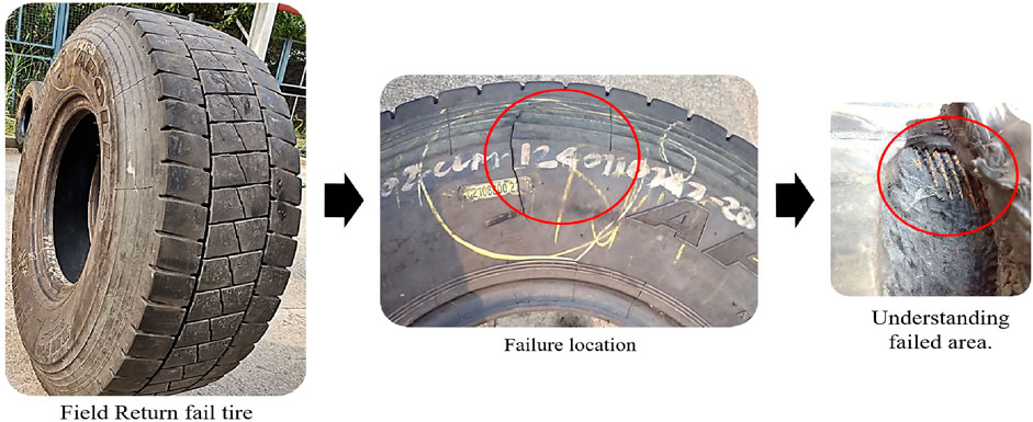
Figure 1. Ply bulge failure in TBR tyre.
Extensive research has been conducted on various tyre failure mechanisms. For instance, belt separation has been studied in detail, with investigations into contributing factors such as belt angle, rubber gauge, and belt width (DeEskinazi and Cembrola, 1984; Lake, 2001; McGinty et al., 2008). Researchers have also examined the direction of crack propagation after initiation and employed optimization techniques to determine the best design parameters (Zhong, 2006; Cho and Lee, 2017). Similarly, studies have been conducted on tread separation (Daws, 2003; Xie et al., 2016) and bead failures (Shilavant et al., 2024; Li et al., 2021). A comprehensive discussion on the causes of various tyre failures is provided in Giapponi’s book (Giapponi, 2008), which extensively covers potential failure mechanisms. However, despite the vast body of literature on tyre failures, research specifically addressing ply bulge failure remains limited. Apart from the work by (Jeong et al., 2019), which employs finite element methods to predict ply bulge failure and optimize design parameters for improved durability, there is a noticeable gap in the literature on this topic.
Tyre failures can result from various factors, including excessive loading (e.g., operating at 200% of the rated load), punctures, or manufacturing defects. This paper, however, focuses on determining whether ply bulge failure is caused by cohesive failure within the rubber or adhesive failure between the rubber and the steel cord. The critical question this paper addresses is: What causes the degradation in bonding? Is it the thickening of the adhesive (CuxS) layer due to aging, which makes the adhesion layer brittle and more susceptible to failure? Or is it the degradation of rubber caused by thermo-oxidative processes due to prolonged exposure to air and elevated temperatures in the shoulder area?
To answer this question, this study investigates the location and mechanism of failure by analyzing crack nucleation and propagation while eliminating external influences such as manufacturing defects or improper usage. A systematic method is introduced to validate the hypothesis, providing a comprehensive understanding of ply bulge failure and establishing a framework for forensic analysis of failures in Truck and Bus Radial (TBR) tyres. In this study, we analyzed 13 failed TBR tyres returned from the field, which varied in type, application, size, and tread pattern. Among these, eight tyres were sourced from the Salem market, while five came from the Bikaner market. Details regarding the tyre types and sizes are provided in Table 1.
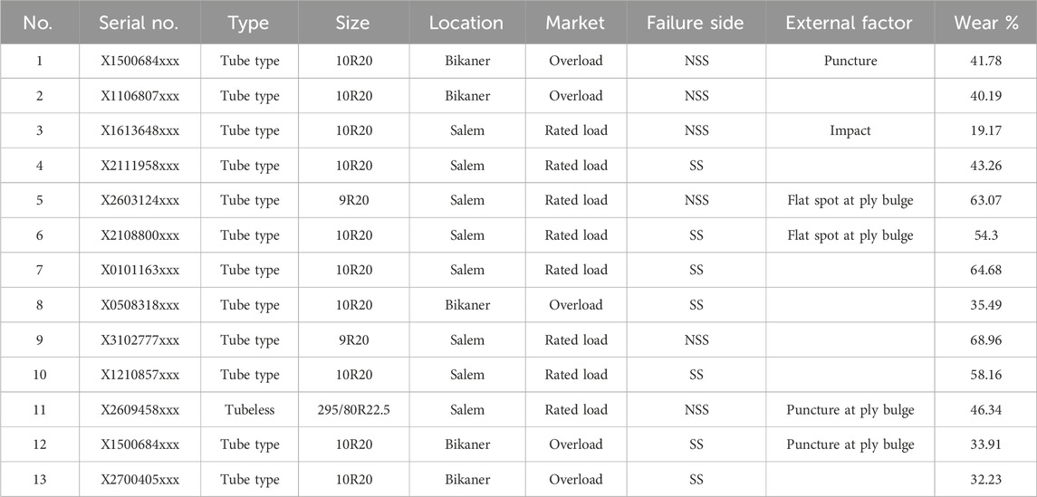
Table 1. Tyre details and application.
This paper is organized as follows: Section 2 provides the theoretical background necessary to understand composite failures, tension distribution across different parts of the tyre, rubber aging, and the adhesion of rubber to steel cords. Section 3 outlines the methodology employed to investigate ply bulge failure. Section 4 presents the results of the multi-step analysis, and Section 5 concludes with key findings and remarks.
Tyre is a complex composite structure consisting of 30 different components. The major components of a typical TBR tyre are tread, belts, carcass ply, sidewall, inner liner, apex and bead wire. Understanding how composites fail is crucial for analyzing tyre failure, as tyres are composite materials. In a TBR tyre, we generally incorporate five steel plies, consisting of four belt plies and one carcass ply (Tang et al., 2022; Yadav et al., 2024). These steel plies are coated with rubber, referred to as the skim compound, which is a thin layer of rubber over the steel cords. This makes our composite a fiber-reinforced rubber (FRR), where the fiber is the steel cord and the matrix is the rubber. Each ply can be referred to as a lamina, and when multiple laminae are stacked together, they form a laminate (Yadav et al., 2024). This section begins by discussing the load transfer between the fiber and the matrix, followed by an exploration of the damage mechanisms in laminates. Next, the causes of rubber degradation are examined, concluding with a discussion on rubber-steel adhesion and its degradation.
In composite materials, the majority of the load is carried by the fibers, while the matrix primarily functions to hold them in place. When a tensile load is applied along the fiber direction, the fiber transfers this load to the matrix through shear stress at the fiber-matrix interface. Initially, the fiber experiences maximum tensile stress, which induces both shear and tensile stresses within the interface. The shear stress is lowest on the fiber side and gradually increases toward the matrix side. Beyond a certain point, the shear stress in the matrix reaches its maximum value, while the tensile stress in the matrix reduces to zero (Hyer and White, 2009). This process is illustrated in Figure 2.
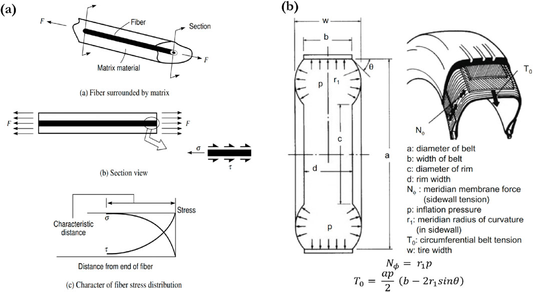
Figure 2. (A) Load transfer process when fiber in tension (Hyer and White, 2009), (B) Tension at carcass ply and belt in radial tyre (Yamagishi et al., 1987).
In tyres, the belt and carcass ply experience tension due to inflation pressure. The tension in the carcass ply depends on the radius of curvature, while the tension in the belt is influenced by the tyre’s outer diameter, width, and angle, as shown in Figure 2. Since these plies collectively form the laminate, multiple local failures must occur for the laminate to fail completely and break into two or more pieces. Here, “local” refers to failures within the individual constituent phases—the fiber and the matrix. This local-level failure is termed “damage”. Therefore, in fibrous composites, damage is a micro-level event. The damage mechanisms in fibrous composites are broadly categorized into three types (Talreja, 1981; Talreja, 1989).
1. Micro-level damage mechanisms: Damage occurs within a lamina.
2. Macro-level damage mechanisms: Damage occurs in laminates.
3. Coupled micro-macro damage mechanisms: Cracking initiates within the lamina, followed by delamination, causing one lamina to separate from another.
In this study, we identify the damage mechanisms using microscopy analysis.
Over time, the rubber in tyres deteriorates due to environmental and mechanical factors, compromising structural integrity and potentially leading to failure. Rubber degradation primarily occurs through two mechanisms: thermo-oxidative aging and mechanical aging. In thermo-oxidative aging, oxygen molecules react with heat, initiating chain scission that breaks rubber molecules, reducing elasticity and increasing stiffness, ultimately leading to crack formation (Mathew and De, 1983). In mechanical aging, the tyre undergoes continuous deformation as it rolls, generating mechanical stresses that gradually weaken the rubber. This results in crack formation at stress concentration areas and eventually leads to fatigue failure (Lee et al., 2004; Weng et al., 2012). In ply bulge failure, cracks initiate near the carcass ply region, where the rubber layer (skim compound) over the carcass ply is very thin. Due to this thin layer, mechanical testing is impractical for comparing the physical properties of failed and new tyre carcass compounds. Instead, we utilized Fourier Transform Infrared Spectroscopy (FTIR) to assess the aging of field-exposed tyres. FTIR is employed to identify and quantify chemical changes in aged rubber compounds. By analyzing specific absorption bands in the infrared spectrum, we can evaluate the degree of aging and degradation. While both aging processes produce similar chemical groups, FTIR allows us to differentiate their contributions by comparing different samples. Thermo-oxidative aging typically results in a higher concentration of carbonyl groups and a reduction in alkene and vinyl groups, whereas mechanical aging produces a mixture of alcohol and carbonyl groups (Komethi et al., 2012; Weng et al., 2012).
In tyres, brass-coated steel wires are used to bond them with rubber. This adhesion is achieved through the formation of a strong interfacial bond facilitated by the Cu/Zn layer. During the curing process, chemical reactions occur between the rubber compound and the brass surface, forming a copper sulfide (CuxS) layer. This layer interlocks with the cross-linked rubber network, enhancing the bond strength. Here, compounding ingredients such as accelerators, sulfur, and cobalt salts play a vital role in promoting metal-sulfur interactions and improving adhesion. The mechanism of rubber-brass adhesion is well described in earlier literature (van Ooij, 1978; Vanooij et al., 2009). The loss of adhesion in the steel cord-to-rubber interfaces is primarily caused by thermal aging, oxygen exposure, and moisture. Thermal aging leads to the thickening of the CuxS layer, as copper inclusions in ZnO react to form crystalline CuxS, making the adhesion interface brittle and prone to cracking under strain. Aging in oxygen oxidizes the CuxS layer to CuSO4, which has poor cohesive strength, reducing adhesion. In the presence of moisture and oxygen, cathodic corrosion occurs, forming Zn+2 ions and Zn(OH)2, further weakening the adhesion layer (Patil and Ooij, 2004). To evaluate the adhesion strength of the carcass ply with rubber, we used a 90°peel test.
A thorough visual inspection was conducted to assess whether external factors such as punctures, impacts, excessive overloading, or overheating contributed to ply bulge failure. The primary objective was to document any external influences that might have led to failure. Before inspection, all tyres were cleaned, and the non-serial side (NSS) (which does not have a serial number) and the serial side (SS) (which has a serial number) were marked with chalk for reference. The inspection process focused on identifying the failure location, examining surrounding areas, and investigating potential causes such as punctures, inner liner splice failure, bead damage, or flat spots. These factors were considered critical, as they could allow air to seep into the tyre cross-section, ultimately leading to ply bulge failure. All 13 tyres were inspected, and their failure locations were marked for further analysis, as shown in Figure 4.
Following the visual inspection, X-ray analysis was conducted to detect defects or damage in the belt area, sidewall, or bead region (Warczek and Zak, 2024). The primary objective was to identify structural damage within the steel components that could be attributed to manufacturing defects. To accurately locate the failure area during X-ray imaging, a pin was placed on the opposite side of the tyre at the marked failure location.
Since this study focuses on ply bulge failure, special attention was given to the upper sidewall region. In this area, the spacing between the carcass cords, known as cord spacing, was examined. Cord spacing refers to the distance between adjacent carcass cords. Excessively large or uneven cord spacing, whether resulting from tyre manufacturing or operational use, can cause the rubber material to deform outward under inflation pressure, leading to gaps between the cords. This deformation reduces the gauge thickness, increasing the likelihood of tears in the rubber, which can ultimately lead to ply bulge failure. Significant or irregular cord spacing near the failure area would be considered a potential manufacturing defect, likely originating from the tyre building machine (TBM).
Shearography, a laser-based technology, was employed to detect anomalies such as air bubbles and separations within the tyres. This method also enables performance testing under varying conditions, including different pressures and temperatures. Following the X-ray analysis, shearography was conducted to identify incipient and hidden separations within the tyres, with the primary objective of locating the initiation points of failure. As illustrated in Figure 6, the shearography images consist of three scans covering eight sectors. Scan 1 corresponds to the bottom side of the tyre, Scan 2 covers the crown region, and Scan 3 focuses on the top side. The tyre’s 360° circumference is divided into eight sectors, each spanning 45°.
After the shearography analysis, the locations of incipient separations were marked. The tyres were then cut into thin sections at these marked locations using a tyre-cutting machine for further examination. The tyre-cutting machine utilizes a diamond-coated wire, in which a thin steel wire is coated with diamond particles. This process ensures precise cuts and smooth surfaces, preventing distortion of the incipient failure location. The tyre cut-sections with incipient separations were then analyzed using a digital microscope, the DinoLite Premier AM7013MZT4. An awl tool was also used to enlarge the incipient areas, where crack initiation occurred within the sample. The primary objective of this analysis was to identify the precise location of crack initiation. Once the crack initiation site was identified, microscopic images of various cut sections were examined to study the direction and pattern of crack propagation.
To investigate whether crack initiation is caused by rubber degradation, an FTIR study was conducted in ATR mode. Rubber samples were collected from the skim rubber layer over the carcass ply cord, specifically from both the crack initiation and non-initiation areas, as shown in Figure 7. To strengthen our findings, we also analyzed two new tyres. From one tyre, a fresh sample was obtained, while the other tyre was subjected to artificial aging in a climatic chamber. The aging process involved exposing the tyre to a controlled environment of 50% nitrogen and 50% oxygen at 100°C for 30 days.
This experimental setup enabled a comprehensive comparison of FTIR spectra.
1. Between new tyres, field-returned tyres with varying wear percentages, and artificially aged tyres in-house testing facility.
2. Between the crack initiation and non-initiation areas of the field-returned tyres.
This methodology provides detailed insights into the chemical changes associated with degradation and crack initiation, enabling a deeper understanding of the failure mechanisms.
To investigate whether crack initiation is caused by a degradation in adhesion strength, a 90°peel test was conducted using a universal testing machine (UTM). This standard test method evaluates rubber-to-metal bonding. Typically, for tyre cut sections, the 90°peel test is carried out in specific areas of the tyre.
• In the crown region, between the ply and the first belt or between the first and second belts.
• In the sidewall region, between the ply and the sidewall rubber compound.
However, since ply bulge failures occur in the shoulder region, performing adhesion tests in this area presented two significant challenges.
1. Difficulty in removing the belt.
2. The thin rubber layer in the shoulder region, which intersects two different rubber compounds, making it impossible to securely hold the sample in the UTM claws.
Given these limitations, an alternative approach was adopted to identify adhesive or cohesive failure. The investigation focused on the ply-to-belt area in the crown region. For this purpose, two sets of tyre cut sections were prepared.
1. Set A: Cut sections from field-return tyres with ply bulges but no visible signs of crack initiation in the shoulder region.
2. Set B: Cut sections from the same field-return tyres with ply bulges and visible crack initiation in the shoulder region.
Both sets underwent the 90°peel test to compare their adhesion characteristics. The sample preparation process for the adhesion test is depicted in Figure 3.
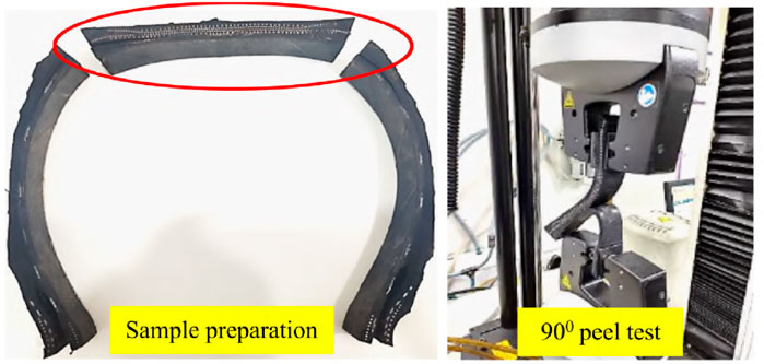
Figure 3. Adhesion test for tyre cut sections.
Upon visually inspecting all the tyres, it was observed that ply bulge failures predominantly occurred in the upper sidewall section. These failures were not restricted to any specific side, whether NSS or SS, and could occur at any circumferential location around the tyre. For reference, the barcode location was designated as 0°, and the inner liner (IL) splice was marked at 180°, as shown in Figure 4A. In all tyres, cord shadows were visible from the inside, and bare cords were observed from the outside, as illustrated in Figure 4B. Three tyres had punctures, but only two of these punctures were near the failure locations. Additionally, flat spots were observed near the failure regions in several tyres, which were attributed to harsh braking. One tyre showed evidence of impact damage, where the failure occurred at the point of impact due to a clear loss of casing integrity. The wear percentage was measured for each tyre. Excluding tyre number 3 (X1613648xxx), the average wear was found to be 48.53%. Market analysis showed that the average tyre wear in Salem was 56.97%, while in Bikaner it was 36.73%. The lower wear percentage observed in the Bikaner region was attributed to overloading conditions, which are commonly practiced by truck drivers in that region. This resulted in earlier failures and lower wear percentages at the time of ply bulge failure. Overall, the visual inspection suggests that external factors such as impact, punctures, flat spots, and overloading significantly contribute to ply bulge failures. Punctures and impacts create entry points for air seepage and moisture infiltration, accelerating rubber aging and reducing its mechanical properties. On the other hand, flat spots and overloading increase stress on the carcass ply, leading to premature failure.
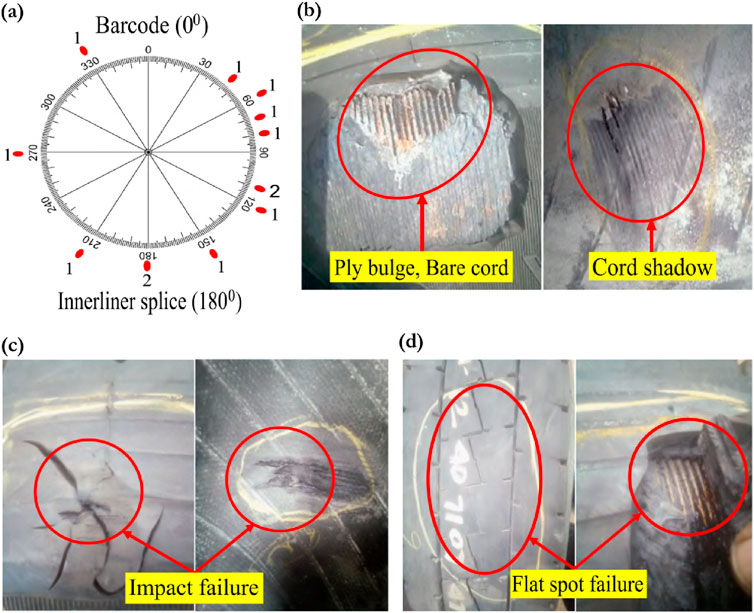
Figure 4. Visual analysis: (A) Failure location at different circumferential positions of the tyre, (B) Bare cord and cord shadow at the failure location, (C) Failure due to impact, (D) Failure due to flat spot.
X-ray analysis of the tyres revealed no significant manufacturing defects. The identification of different components in the X-ray images and analysis of the regions near the failure were conducted as shown in Figure 5. The cord spacing near the failure regions was within acceptable limits in all tyres, indicating that no manufacturing issues contributed to the ply bulge failure.
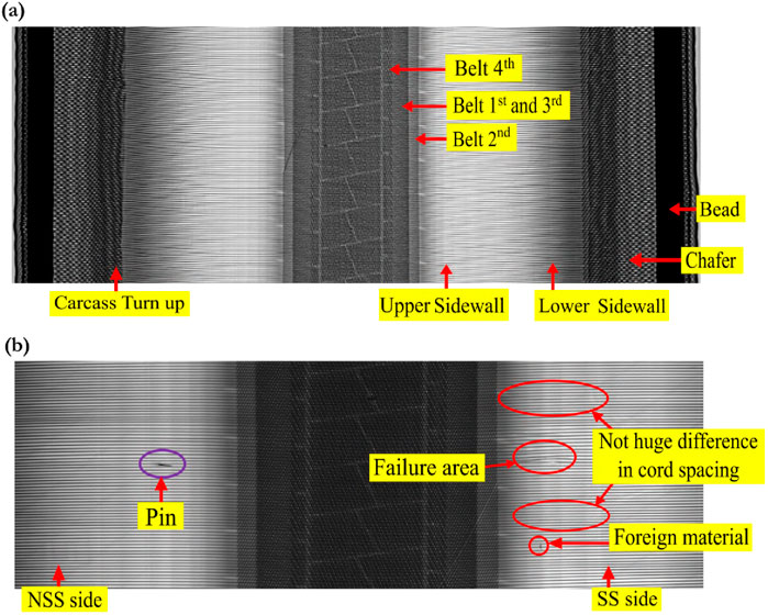
Figure 5. (A) Identifying different components from the X-ray image, (B) X-ray image of failed tyre.
In the shearography images, various fringes were observed, indicating different levels of separation. As shown in Figure 6, areas encircled in red represent major separations, while those encircled in yellow indicate minor separations. The shearography analysis revealed separations in several key regions of some tyres, including the turn-up region, belt edge, and ply separation at the shoulder. An example is illustrated in Figure 6, where: ‘1’ indicates a major separation in the turn-up region, ‘2’ denotes a minor separation in the turn-up region, ‘3’ indicates incipient belt edge separation, ‘4’ shows intense ply separation at the shoulder, and ‘5’ represents incipient ply separation at the shoulder. Upon reviewing the shearography images, it was determined that six tyres—numbers 1, 2, 7, 10, 11, and 12 — exhibited incipient ply separations. Since these are incipient areas, unaffected by external environmental factors, they provide a clearer understanding of the separation locations. The cut sections of these tyres were made at the identified incipient locations.
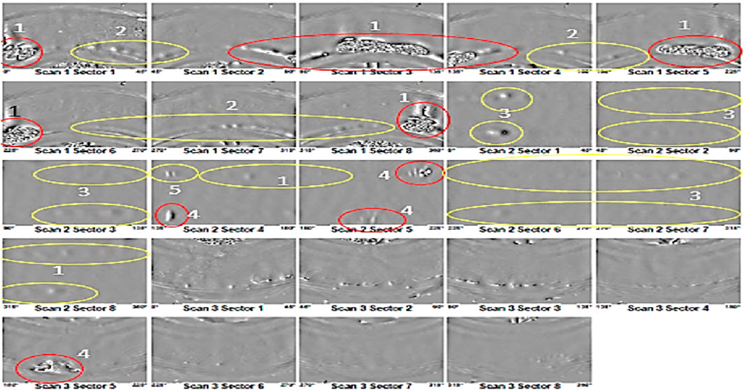
Figure 6. Shearography image of Tyre 1.
A detailed analysis of all tyre cut sections was conducted, focusing on identifying any offsets in the geometrical arrangement, such as belt offset, turn-up offset, and rubber gauge offset. No deviations outside the acceptable range were observed in these parameters.
Subsequently, microscopic image analysis was performed on six incipient cut sections. Initially, the cut sections were examined to identify the initiation areas, as shown in Figure 7A. From Figure 7A, it is evident that crack initiation occurs directly below the mid-region of the shoulder cushion within the carcass ply.
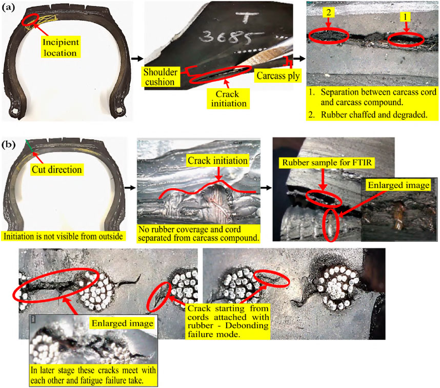
Figure 7. Microscopic analysis of tyre: (A) On the cut section, (B) Within the cut section.
A separation between the cord and skim compound is clearly visible, with the cords exhibiting a lack of rubber coverage due to chafing and degradation under rolling conditions at the time of crack initiation. Additionally, the presence of brass coating on the carcass cord was observed.
In the second stage of analysis, a perpendicular cut was made at the shoulder section of the tyre cut section using a cutting tool, focusing on the carcass ply region, as illustrated in Figure 7B. The resulting images revealed that crack initiation occurs at the interface where the cords are bonded to the rubber, indicating that the initiation does not occur in the rubber matrix phase. Instead, the initiation is observed as a de-bonding failure mode at the cord-rubber interface along one of the cords, which subsequently propagates to nearby adjacent cords.
From a composite perspective, treating all plies as individual laminae, the failure mechanism does not occur between the laminae; rather, it originates within a single lamina (the carcass ply). The failure initiates as transverse fiber debonding along the steel cords, as shown in images 1 and 2 of Figure 8. This debonding occurs due to the combined effects of stress concentration and degradation at the cord-rubber interface.

Figure 8. Crack nucleation and propagation.
As the crack grows to a sufficient length along the cord, it transfers into the rubber matrix, leading to localized crack propagation towards adjacent cords, as depicted in images 3 and 4 of Figure 8. This progression highlights a coupled damage mechanism where the micro-level debonding failure transitions into macro-level delamination.
When the crack becomes sufficiently large, spanning multiple cords (typically 2–4 cords), a macro-level delamination occurs. This delamination causes the separation of the carcass ply from the surrounding structure, as illustrated in images 5 and 6 of Figure 8. The delamination leads to tearing and squeezing of the ply layers, compromising the integrity of the inner liner. This results in air leakage, bulging of the upper sidewall region, and, ultimately, catastrophic failure through bursting.
Overall, the damage mechanism involves a combination of micro- and macro-scale phenomena. At the micro-scale, transverse fiber debonding originates along the steel cords due to shear stress and interfacial degradation. At the macro-scale, delamination progresses due to the interaction of multiple local cracks, culminating in the structural failure of the tyre.
In summary, we can conclude that cracks initially form in one of the carcass cords at the shoulder area. The microscopic images suggest a debonding failure mechanism. Additionally, in some tyres, a reddish-brown discoloration, particularly in the warp region of the cord, was observed. This discoloration is likely due to the oxidation of the steel cord.
The objective of this study is to determine whether the rubber is undergoing degradation. To achieve this, we focus on specific regions of the FTIR spectrum, particularly the carbonyl, alkene, and vinyl regions. Thermo-oxidative degradation results in the formation of aldehydes and ketones, leading to an increase in carbonyl, hydroxyl, and ether groups. These changes are identifiable in the following spectral regions.
• 3,400 cm−1 to 3,300 cm−1 (hydroxyl groups),
• 1,800 cm−1 to 1,700 cm−1 (carbonyl groups), and
• 1,200 cm−1 to 1,000 cm−1 (ether groups).
Conversely, oxidation results in a decrease in intensity within the following regions.
• 840 cm−1 to 820 cm−1 (out-of-plane bending of = C-H in alkenes),
• 1,660 cm−1 to 1,640 cm−1 (C=C stretching in alkenes), and
• 910 cm−1 to 890 cm−1 (out-of-plane bending of = C-H in vinyl groups).
The region from 1,600 cm−1–1,500 cm−1 poses a challenge for analysis due to the overlap of signals from various functional groups, including alkenes, amines, secondary amides, and benzene. To investigate the role of rubber aging in ply bulge failure, we compared the FTIR spectra of selected field-return tyres with those of fresh tyres and a tyre subjected to controlled aging in a climatic chamber, which also exhibited ply bulge failure. This comparison allows us to assess the extent to which material aging contributes to failure. The FTIR spectra, as shown in Figure 9, use different colors to represent tyres at various stages of wear and aging.
• Black represents the Fresh Tyre with 0% wear.
• Dark Blue represents Tyre 3 with 19.3% wear.
• Orange represents Tyre 12 with 33.91% wear.
• Light Blue represents Tyre 1 with 41.78% wear.
• Green represents Tyre 10 with 58.16% wear.
• Pink represents the Climatic Chamber Tyre.
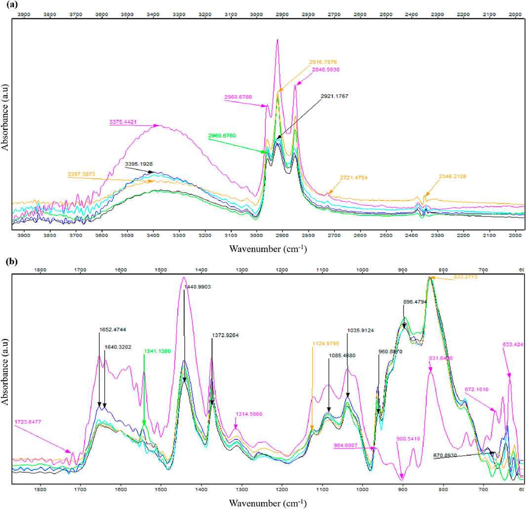
Figure 9. FTIR spectra of tyre cut sections: (A) from 4,000 cm−1–1,900 cm−1 and (B) from 1,900 cm−1–600 cm−1.
The wear rate cannot be directly correlated with oxidation, as the FTIR analysis reveals varying chemical changes that are not uniformly dependent on wear levels. For tyres with less wear, a significant increase in OH groups is observed, whereas tyres with higher wear show a notable increase in CH2 groups. The increase in CH2 and CH3 groups in field-return tyres suggests the occurrence of saturation, driven by mechanical strain and thermal aging, particularly in the shoulder region. These processes cause the breaking of C-C and C-S bonds, leading to the formation of alkane groups.
Interestingly, no formation of carbonyl groups is detected in the field-return tyres, indicating that oxidation is not a predominant process. This absence is explained by the action of antioxidants, which consume carbonyl groups and convert them into by-products such as secondary amides, imines, and nitrous compounds. Furthermore, no significant decrease in vinyl and alkene groups is observed in the field-return tyres when compared to fresh tyres. In contrast, the climatic chamber tyre exhibits distinct chemical changes. The vinyl group is nearly absent, and a decrease in alkene groups is observed. This behavior confirms that degradation is more pronounced in tyres subjected to accelerated aging conditions in the climatic chamber.
Overall, the findings suggest minimal rubber degradation in the tyre carcass ply compound of field-return tyres. The compound remains structurally sound, with limited degradation that does not significantly affect its physical properties. Therefore, failure is unlikely to result from compound property degradation.
The adhesion level in tyre cut section is different at different regions due the requirement. Since sidewall continuously go under bending we need higher adhesion strength thus in rubber the additives are added accordingly. According the manufacturer, the specification set for the new tyre to pass adhesion strength in crown region is 23 kgf/inch and in for sidewall is 100 kgf/inch. Since we are doing adhesion test of field return tyre so the value we will get will be less. Thus here we have done a relative comparison between set A (section with no initiation) and set B (section with initiation). The result of adhesion test is given in Table 2.
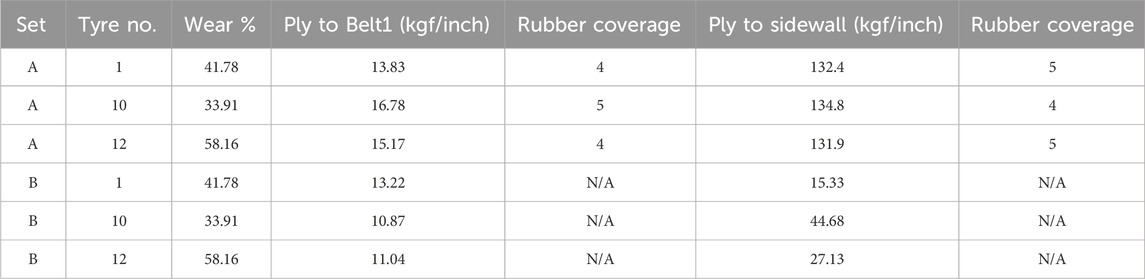
Table 2. Adhesion test result.
From Table 2 we can clearly see that the section having initiation have low adhesion strength and rubber coverage between ply to belt 1 and ply to sidewall, compared to the section with no initiation. After the test we also compared the rubber coverage of the crown portion in Set A with those in Set B as shown in Figure 10. It can be been seen clearly from the image that in Set A, only pure cohesive failure occurred, i. e., rubber coverage is greater than 3. On the other hand Set B exhibited adhesive/cohesive failure after conducting a 90◦ peel test. Overall, conclusion regarding the adhesion strength values of the crown region between the carcass ply and the first belt is as follows.
• Set A: Minimum adhesion strength is approximately 13 kgf/inch.
• Set B: Maximum adhesion strength is also approximately 13 kgf/inch.
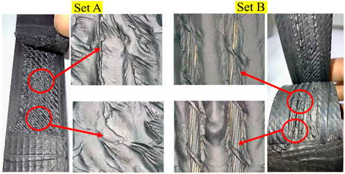
Figure 10. Surface of ply to first belt after adhesion test.
This study provides a comprehensive investigation into the causes and mechanisms of ply bulge failures in truck and bus radial (TBR) tyres, addressing a critical gap in the existing literature. The failure mechanism is initiated by the breakage of a weak interphase, as confirmed through microscopic analysis. Once a crack forms at the cord-rubber interface, it propagates along the cord surface, causing carcass cords in the shoulder region to debond from the surrounding rubber. This debonding creates a stress concentration site that intensifies as the tyre rolls under load. The increasing stress leads to crack propagation across adjacent cords, resulting in the detachment of multiple cords and the progressive separation of the carcass ply, which ultimately manifests as a ply bulge in the shoulder region.
As the separation progresses, the carcass ply ability to support load diminishes. Detached cords are pulled inward due to inflation pressure, forming cord shadows and tearing the inner liner. This damage facilitates air leakage, ultimately leading to a bulge in the upper sidewall region and catastrophic tyre failure. Key findings from the failure analysis are as follows.
1. External factor: Visual analysis confirmed that external factors such as impact, punctures, flat spots, and overloading can contribute to ply bulge failures by accelerating local stress accumulation.
2. Manufacturing factor: X-ray and cut-section analyses revealed no deviations in geometry, such as cord spacing, rubber gauge, or belt offset, confirming that manufacturing issues were not the cause of the failure.
3. Rubber aging: FTIR analysis demonstrated that the carcass ply rubber remained in good condition, with antioxidants effectively preventing degradation. Rubber aging was not a contributing factor.
4. Adhesive layer degradation: The primary cause of failure was the aging and degradation of the adhesive layer at the cord-rubber interface. Microscopic analysis and 90° peel-off tests confirmed reduced adhesion strength in tyres exhibiting crack initiation.
Thus, this research suggests that to delay ply bulge failure in TBR tyres, the tyre industry should focus on two key areas. The first is enhancing cord-rubber adhesion. This can be achieved by developing new carcass ply rubber compounds with improved adhesion through optimized rubber formulations. Additionally, collaboration with steel cord manufacturers to enhance brass coating on steel cords can further strengthen the bond between the rubber and reinforcement. The second area is optimizing tyre design. Modifying the carcass ply radius can help distribute tension more evenly and reduce localized stress, while adjustments to the belt structure can increase circumferential rigidity, improving overall tyre durability. By addressing these factors, the industry can enhance tyre performance and longevity, ultimately reducing the risk of ply bulge failures in commercial TBR tyres.
The original contributions presented in the study are included in the article/supplementary material, further inquiries can be directed to the corresponding author.
AY: Conceptualization, Data curation, Formal Analysis, Investigation, Methodology, Validation, Visualization, Writing – original draft, Writing – review and editing. CJ: Supervision, Writing – review and editing, Conceptualization, Project administration. PK: Supervision, Writing – review and editing, Conceptualization, Project administration. ND: Supervision, Writing – review and editing, Conceptualization, Project administration.
The author(s) declare that no financial support was received for the research and/or publication of this article.
The authors would like to express their gratitude to Apollo Tyres, Global R&D centre, India for supplying research material, equipment, guidance and their unwavering support during the course of this research.
Authors CJ and PK were employed by Apollo Tyres Ltd. Global R&D Centre - Asia.
The remaining authors declare that the research was conducted in the absence of any commercial or financial relationships that could be construed as a potential conflict of interest.
The author(s) declare that no Generative AI was used in the creation of this manuscript.
All claims expressed in this article are solely those of the authors and do not necessarily represent those of their affiliated organizations, or those of the publisher, the editors and the reviewers. Any product that may be evaluated in this article, or claim that may be made by its manufacturer, is not guaranteed or endorsed by the publisher.
Acosta, S. M., Oliveira, R. M. A., and Sant’Anna, A. M. O. (2024). Machine learning algorithms applied to intelligent tyre manufacturing. Int. J. Comput. Integr. Manuf. 37, 497–507. doi:10.1080/0951192X.2023.2177734
Behnke, R., and Kaliske, M. (2018). Finite element based analysis of reinforcing cords in rolling tires: influence of mechanical and thermal cord properties on tire response. Tire Sci. Technol. 46, 294–327. doi:10.2346/tire.18.4604010
Bogdevicius, M., Karpenko, M., and Rozˇyte˙, D. (2022). “Methodology for determination coefficients values of the proposed rheological model for the tire tread,” in Transbaltica XII: transportation science and technology. Editors O. Prentkovskis, I. Yatskiv, (Jackiva), P. Skacˇkauskas, R. Junevicˇius, and P. Maruschak (Cham: Springer International Publishing), 16–27.
Chen, K. Y., and Yeh, C. F. (2018). Preventing tire blowout accidents: a perspective on factors affecting drivers’ intention to adopt tire pressure monitoring system. Safety 4, 16. doi:10.3390/safety4020016
Cho, J. R., and Lee, J. H. (2017). Multi-objective optimum design of tbr tire structure for enhancing the durability using genetic algorithm. J. Mech. Sci. Technol. 31, 5961–5969. doi:10.1007/s12206-017-1140-y
Cohn, A. (2015). Commercial trailer tires: tire inflation and its effect on rolling resistance, fuel economy, and tire footprint. Tire Sci. Technol. 43, 144–162. doi:10.2346/tire.15.430201
Daws, J. (2003). Failure analysis of tire tread separations. Pract. Fail. Anal. 3, 73–80. doi:10.1361/152981503771816790
DeEskinazi, J., and Cembrola, R. J. (1984). A parametric study on interlaminar shear strains in cord-rubber composites. Rubber Chem. Technol. 57, 168–183. doi:10.5254/1.3535992
Ghosh, P., Chanda, J., and Mukhopadhyay, R. (2023). Parameters influencing fatigue characteristics of tyre tread rubber compounds, 289. doi:10.1007/122022115
Hongling, L., Yude, D., Lei, Q., and Juxin, S. (2022). Belt width optimization for tire durability enhancement. Proc. Institution Mech. Eng. Part D J. Automob. Eng. 236, 1628–1640. doi:10.1177/09544070211035249
Hyer, M. W., and White, S. R. (2009). Stress analysis of fiber-reinforced composite materials. Lancaster, PA: DEStech Publications, Inc.
Jeong, K. M., Kim, K. W., and Kim, J. H. (2019). Global-local finite element analysis for predicting separation in cord-rubber composites of radial truck tires. Open J. Model. Simul. 07, 190–202. doi:10.4236/ojmsi.2019.74011
Komethi, M., Othman, N., Ismail, H., and Sasidharan, S. (2012). Comparative study on natural antioxidant as an aging retardant for natural rubber vulcanizates. J. Appl. Polym. Sci. 124, 1490–1500. doi:10.1002/app.35160
Kost, A., Altabey, W. A., Noori, M., and Awad, T. (2019). Applying neural networks for tire pressure monitoring systems. SDHM Struct. Durab. Health Monit. 13, 247–266. doi:10.32604/sdhm.2019.07025
Kunkyin-Saadaari, F., Gyebuni, R., and Asamoah-Danquah, C. (2024). Supervisor-field engineering approach (s-fea) of determining tyre failures in the haul trucks at newmont ahafo mine. Eng. Appl. Sci. 9, 20–34. doi:10.11648/j.eas.20240903.11
Lake, G. J. (2001). Application of fracture mechanics to crack growth in rubber-cord laminates. Rubber Chem. Technol. 74, 509–524. doi:10.5254/1.3547649
Lee, B. L., Liu, D. S., Chawla, M., and Ulrich, P. C. (2004). Fatigue of cord-rubber composites. Rubber Chem. Technol. 67, 761–774. doi:10.5254/1.3538708
Li, Y., Sun, X., Song, J., Zhang, S., and Han, S. (2021). Topological structure and experimental investigation of a novel whole tire bead. Mater. Des. 203, 109592. doi:10.1016/J.MATDES.2021.109592
Li, Y., and West, R. L. (2019). Rolling resistance revisited. Tire Sci. Technol. 47, 77–100. doi:10.2346/tire.19.150089
Liang, C., Gao, Z., Hong, S., Wang, G., Asafo-Duho, B. M. K., and Ren, J. (2021). A fatigue evaluation method for radial tire based on strain energy density gradient. Adv. Mater. Sci. Eng. 2021. doi:10.1155/2021/8534954
Mangal, S., Ghosh, P., Rao, K. V., and Mukhopadhyay, R. (2021). Variable modulus approach to optimize tire rolling resistance. Tire Sci. Technol. 49, 39–54. doi:10.2346/tire.19.180200
Mathew, N. M., and De, S. K. (1983). Thermo-oxidative ageing and its effect on the network structure and fracture mode of natural rubber vulcanizates. Polymer 24, 1042–1054. doi:10.1016/0032-3861(83)90158-1
McGinty, R. D., Rhyne, T. B., and Cron, S. M. (2008). Analytical solution for the stresses arising in +/- angle ply belts of radial tires. Tire Sci. Technol. 36, 244–274. doi:10.2346/1.2999704
Patil, P. Y., and Ooij, W. J. V. (2004). Mechanism of adhesion degradation of rubber to brass-plated steel cords. J. Adhesion Sci. Technol. 18, 1367–1394. doi:10.1163/1568561042323266
Rhyne, T. B., and Cron, S. M. (2012). A study on minimum rolling resistance. Tire Sci. Technol. 40, 220–233. doi:10.2346/tire.12.400401
Shilavant, R., Samui, B. K., Chanda, J., Ghosh, P., Mukhopadhyay, R., and Banerjee, S. S. (2024). A critical review on fractographic studies of steel cord and bead wire used in tyre reinforcement. Prog. Rubber, Plastics Recycl. Technol. 40, 98–117. doi:10.1177/14777606231201866
Talreja, R. (1981). Fatigue of composite materials: damage mechanisms and fatigue-life diagrams. Proc. R. Soc. Lond. Ser. A Math. Phys. Sci. 378. doi:10.1098/rspa.1981.0163
Talreja, R. (1989). Damage development in composites: mechanisms and modelling. J. Strain Analysis Eng. Des. 24, 215–222. doi:10.1243/03093247V244215
Tang, X., Xie, J., Xie, H., and Zhang, H. (2022). Predictions of three-dimensional contact stresses of a radial truck tire under different driving modes. Adv. Mech. Eng. 14, 168781322210923. doi:10.1177/16878132221092346
van Ooij, W. J. (1978). Mechanism of rubber-to-brass adhesion: effect of rubber composition on the adhesion. Rubber Chem. Technol. 51, 52–71. doi:10.5254/1.3535727
Vanooij, W. J., Harakuni, P. B., and Buytaert, G. (2009). Adhesion of steel tire cord to rubber. Rubber Chem. Technol. 82, 315–339. doi:10.5254/1.3548251
Wallaschek, J., and Wies, B. (2013). Tyre tread-block friction: modelling, simulation and experimental validation. Veh. Syst. Dyn. 51, 1017–1026. doi:10.1080/00423114.2013.803580
Waluś, K. J., and Warszczyński, J. (2022). Analysis of the damage propagation process during actual operation of a truck tire - a case study. SAE Int. J. Transp. Saf. 11. doi:10.4271/09-11-01-0006
Wang, W., Yan, S., and Zhao, Y. (2015). Numerical and experimental studies of a radial truck tire with tread pattern. Simulation 91, 970–979. doi:10.1177/0037549715608434
Wang, Y., Wei, Y., Feng, X., and Yao, Z. (2012). Finite element analysis of the thermal characteristics and parametric study of steady rolling tires. Tire Sci. Technol. 40, 201–218. doi:10.2346/tire.12.400304
Warczek, J., and Zak, K. (2024). The assessment of the technical condition of a tire belt using computed tomography. Eksploat. i Niezawodn. 26. doi:10.17531/ein/183177
Weng, G., Huang, G., Lei, H., Qu, L., Zhang, P., Nie, Y., et al. (2012). Crack initiation of natural rubber under high temperature fatigue loading. J. Appl. Polym. Sci. 124, 4274–4280. doi:10.1002/app.35408
Xie, M., Tang, H., and Yao, H. (2016). Failure analysis of tire separation in two-sized tires on airbus planes. Eng. Fail. Anal. 61, 21–27. doi:10.1016/j.engfailanal.2015.07.006
Yadav, A., Gandecha, A., and Mahajan, J. (2024). Symmetric laminates for enhanced tire durability: a numerical study on belt edge separation. Proc. Institution Mech. Eng. Part D J. Automob. Eng. doi:10.1177/09544070241231031
Yamagishi, K., Togashi, M., Furuya, S., Tsukahara, K., and Yoshimura, N. (1987). A study on the contour of the radial tire: rolling contour optimization theory — rcot. Tire Sci. Technol. 15, 3–29. doi:10.2346/1.2148779
Yang, D., Li, J., Huang, C., Li, K., Lu, G., and Guo, K. (2024). A review of research on tire burst and vehicle stability control. Sci. Prog. 107, 00368504241272478. PMID: 39285777. doi:10.1177/00368504241272478
Keywords: ply bulge, truck and bus radial (TBR), x-ray, shearography, FTIR, 90°peel test, adhesive failure
Citation: Yadav A, Jiju CM, Kumar P and Das NC (2025) Characterization of ply bulge failures in truck bus radial tyres. Front. Mech. Eng. 11:1576195. doi: 10.3389/fmech.2025.1576195
Received: 13 February 2025; Accepted: 31 March 2025;
Published: 09 April 2025.
Edited by:
Mohit Goswami, Technion Israel Institute of Technology, IsraelReviewed by:
Michał Stosiak, Wroclaw University of Science and Technology, PolandCopyright © 2025 Yadav, Jiju, Kumar and Das. This is an open-access article distributed under the terms of the Creative Commons Attribution License (CC BY). The use, distribution or reproduction in other forums is permitted, provided the original author(s) and the copyright owner(s) are credited and that the original publication in this journal is cited, in accordance with accepted academic practice. No use, distribution or reproduction is permitted which does not comply with these terms.
*Correspondence: Ankush Yadav, eWFkYXZhbmt1c2g5NDhAZ21haWwuY29t
Disclaimer: All claims expressed in this article are solely those of the authors and do not necessarily represent those of their affiliated organizations, or those of the publisher, the editors and the reviewers. Any product that may be evaluated in this article or claim that may be made by its manufacturer is not guaranteed or endorsed by the publisher.
Research integrity at Frontiers
Learn more about the work of our research integrity team to safeguard the quality of each article we publish.