
94% of researchers rate our articles as excellent or good
Learn more about the work of our research integrity team to safeguard the quality of each article we publish.
Find out more
ORIGINAL RESEARCH article
Front. Mech. Eng., 02 April 2025
Sec. Engine and Automotive Engineering
Volume 11 - 2025 | https://doi.org/10.3389/fmech.2025.1543967
 Hainan Li
 Yang Li*
Introduction: With the increasing demand for garbage disposal, complex operating environments and frequent use require garbage truck manipulators to have better performance.
Methods: This study designs a multifunctional robotic arm for garbage trucks, which has three basic degrees of freedom, is driven by hydraulic cylinders, and has a claw type end effector. Through the theory of relative motion of linkage mechanisms, the motion mechanics, including forward and inverse kinematics problems, are analyzed, and methods for calculating joint driving forces, rod angular velocities, and other parameters are determined. In structural optimization design, reducing the weight of the robotic arm is taken as the objective function. At the same time, considering performance indicators such as stiffness and strength, material selection, manufacturing errors, and cost constraints are set as constraints, and optimization is carried out using methods such as finite element analysis and topology optimization.
Results: After structural optimization, the overall mass of the objective function reached 64.39 kg after the 11th optimization, a decrease of about 14.28% compared to the initial 75.12 kg. In terms of manufacturing and processing factors, the optimized processing accuracy has been improved to ±0.15 mm, the cutting speed of some materials has been increased by about 20%, and the mold production cycle has been shortened by about 30%.
Discussion: The results show that the stress distribution of the optimized structure has changed but still meets the requirements of strength and stiffness. This optimized design effectively improves the performance of the robotic arm, reduces costs, and is beneficial for more stable and efficient operations in garbage collection and transportation.
The prosperity of the national economy and the acceleration of urbanization have led to an annual increase in urban waste production in China, and the problem of waste disposal is becoming increasingly serious. According to relevant statistical data, the urban waste production has exceeded 200 million tons and is still growing at a rate of about 8% per year. Improper garbage disposal not only causes serious pollution to the environment, but also triggers a series of social problems (Liu and Wang, 2023). In recent years, the waste disposal industry has experienced rapid development. The types and functions of garbage trucks are constantly improving, and their technological level is constantly improving. The demand and application scope of garbage trucks are also constantly expanding (Sundaralingam and Ramanathan, 2023). The Multi-Functional Robotic Arm (MFRA) of the garbage truck, as a key component in the garbage disposal process, is of great significance for improving garbage collection efficiency and reducing labor intensity for workers. Regarding the design and analysis of a robotic arm, Meng et al. designed a new type of robotic arm that combines multiple linkages to improve the contact surface and enhance gripping stability during the gripping process. The experiment confirmed that the robotic arm had excellent grasping stability (Meng et al., 2024). Aqib et al. proposed a multi-functional under-actuated dual finger adaptive fixture design that combines a multi joint closed chain mechanism and a multi-joint dual parallelogram mechanism to achieve the maximum number of grasping techniques. By establishing a complete mathematical model and conducting simulation verification, it was found that the fixture has excellent stable grasping ability (Aqib et al., 2024). For the optimization of the robotic arm, Bogrekci used ANSYS Mechanical to perform parametric stress analysis on the steel wheels of heavy-duty commercial vehicles with four different ventilation hole designs. They also utilized ANSYS Workbench and response surface optimization module, combined with multi-objective genetic algorithm, to achieve optimization of wheel weight. The half-moon-shaped ventilation hole design had the greatest potential in reducing weight, with a weight reduction of 2.05% compared to the original design, making it the optimal choice (Bogrekci et al., 2024). Kouritem et al. proposed a multi-objective design mechanism that selects appropriate materials and physical dimensions through stress analysis and vibration analysis to minimize the initial and operational costs of industrial robot arms. Finally, a customized robot arm structure combining magnesium aluminum alloy with high safety frequency operation range was proposed, which optimized the motion trajectory and reduced power consumption (Kouritem et al., 2022).
As the core component to realize efficient collection and transfer of garbage, the performance of MRFA of garbage truck directly affects the efficiency and quality of garbage disposal. The finite element analysis of the MRFA of garbage truck can accurately simulate its mechanical behavior under different working conditions, and provide a key basis for structural optimization. At present, some scholars have studied the finite element analysis of robotic arm. Alshihabi et al. adopted the method of combining modal analysis and topology optimization to first analyze the kinematics and dynamics of the robot arm to determine the high-torque joints, then carried out finite element analysis on the key joints, and redesigned the joints through topology optimization. The results show that after the redesign of three different topological geometrics and two different unit sizes, the maximum weight of the manipulator component is reduced by 29.37%, and the stress under key working conditions is reduced by 41%. Moreover, the effectiveness of the optimized design is verified by experimental modal analysis (Alshihabi et al., 2024). The advantages of this method are that it can effectively reduce weight, reduce stress and improve reliability. The disadvantages may be that the analysis process is complicated, the computing resources are required, and the attempts of different topological geometries and element sizes are time-consuming. Ding et al. modeled a variety of soft robot actuators in a virtual environment and experimentally verified them by manufacturing a prototype of a cable driven soft robot arm and a cylindrical soft module driven by a shape memory alloy spring. The results show that the model has sufficient accuracy, and this technology can be widely used in modeling and simulation of other soft robots (Ding et al., 2022). The advantage of this method is that it can solve the dynamic simulation problem of soft robot effectively and has a wide application range. The disadvantage is that in the early stage of the promotion of the new technology, the relevant technical support is not perfect, the professional knowledge of the operator is required to be high, and the model establishment process may be more complicated, requiring more time and energy to adjust and optimize the parameters. Koti et al. used the finite element method to model the flexible single-link robotic arm and carried out static structure analysis and state analysis, taking into account the influence of the cone Angle of the conical flexible composite robot arm, and also carried out material optimization. Results Modeling, stress and deformation analysis, modal frequency calculation and life prediction of the flexible manipulator were completed (Koti et al., 2022). The advantage of this method is that it can comprehensively and deeply analyze the various properties of the flexible manipulator, and help the material selection and structure optimization. The disadvantage is that the finite element model construction is complicated, requiring a large number of accurate parameter input, requiring high computational resources, and there are deviations between simulation and practice.
In summary, for the current research on the MRFA of garbage trucks, some scholars have used modal analysis, topology optimization, finite element analysis and other methods to analyze and optimize it, and have achieved certain results in weight reduction, stress reduction, simulation and other aspects. At present, the research on MRFA of garbage trucks has made progress by means of modal analysis and topology optimization, but there are limitations in the analysis process, computing resource requirements, topology attempts and operator skill requirements, etc. Besides, the construction of finite element model is complicated, parameter adjustment is time-consuming, and there are differences between simulation and practice. Therefore, the research will deeply analyze the mechanical characteristics of the multi-functional robot arm of garbage trucks under complex actual conditions, and optimize its design. The innovation of this research method is that during the design, the position, attitude and joint driving force of the component are determined through a variety of calculations. In the optimization design of the structure, weight reduction is the main objective function while other performance is taken into account, and the work safety factor and stress constraint are comprehensively considered to ensure safety and stability. The disadvantages of complex analysis process, high requirement of computing resources, difficulty of model construction and large deviation between simulation and practice are overcome. This research can accurately target the special application scenarios of the multi-functional manipulator of garbage trucks, significantly improve the performance of the manipulator arm, extend the service life, provide a new and powerful support for its design and improvement, and help improve the efficiency of garbage disposal.
The robotic arm needs to have three basic degrees of freedom to ensure flexible operation in different environments. There should be sufficient gripping power to meet the needs of garbage grabbing, and a fast response speed can enable it to complete grabbing and releasing in a short time. The robotic arm also needs sufficient working space and load-bearing capacity to ensure smooth loading and unloading of garbage. The driving method is hydraulic cylinder, which can achieve high power and small volume. At the same time, the installation of the cylinder and the direction of force application should be considered to reduce the number of cylinders and avoid motion interference (Srinivas et al., 2024). Based on the above analysis, this study constructs a corresponding coordinate system for the overall structure of garbage trucks, as shown in Figure 1.
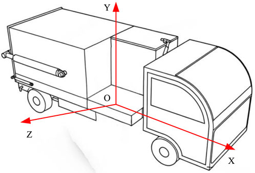
Figure 1. Vehicle coordinate system.
In Figure 1, the coordinate system has three axes, X, Y, and Z, with point O as the origin. The Y-axis is vertically upward, the X-axis extends along the length direction of the garbage truck body, and the Z-axis is perpendicular to the X and Y-axes, forming a three-dimensional spatial coordinate system. This coordinate system provides a spatial reference basis for determining position and orientation, motion analysis, and establishing three-dimensional geometric models in the subsequent design process of robotic arms. There are two design schemes for the end effector, namely, bucket hanging and claw holding (Tang and Xie, 2023). The bucket hanging type is simple, has a low failure rate, is convenient, and has low cost, but it requires high operational skills from the driver. Claw holding has multiple degrees of freedom and easy positioning, but its structure is complex and costly (Seguin et al., 2023). After comprehensive consideration, the claw holding end effector is chosen. A box truck is selected and the carriage is modified to install a garbage collection and transportation robotic arm. Key technical indicators for automatic tilting of robotic arms are developed based on actual scenarios, and a 3D geometric model of the robotic arm is created using SolidWorks. The front end of the garbage truck is equipped with a frame, and a hydraulic cylinder is lifted to control the lifting arm. The slider is driven by an oil motor. The hydraulic cylinder is flipped to drive the flipping arm. The gripper mechanism controls the movement of the gear rack through the rotation of the gripper and the extension and contraction of the hydraulic cylinder piston (Zhang et al., 2022; Peng et al., 2023). The 3D model of the robotic arm is shown in Figure 2.
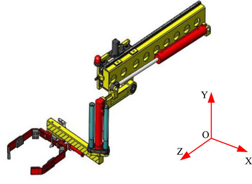
Figure 2. Three dimensional model of robotic arm.
In Figure 2, the longer yellow rod in the upper part of the model is the main load-bearing structure of the robotic arm, with some circular holes distributed on top for weight reduction or installation of other components. The red hydraulic cylinders are distributed at different positions of the robotic arm, providing power for the movement of the robotic arm. The claw mechanism below is red and is the end effector used to grab garbage. This model is a three-dimensional coordinate system with point O as the origin, consisting of X, Y, and Z-axes, used to determine the direction of the robotic arm in space.
The key performance requirements of the manipulator such as basic freedom, grasping force and reaction speed were defined in the multifunctional manipulator scheme formulation process. The hydraulic cylinder driving mode and the claw end actuator were selected, and the three-dimensional geometric model of the manipulator was constructed based on the vehicle coordinate system. On this basis, the mechanical analysis method of manipulator motion will be further discussed in order to further reveal its motion laws and mechanical characteristics, and lay a solid theoretical foundation for the subsequent structural optimization design.
A robotic arm is composed of a linkage mechanism, and its motion depends on the relative motion of the rotating joint and the moving joint. This study is based on the theory of relative motion of linkage mechanisms, analyzing the kinematics of robotic arms, with a focus on the forward and inverse kinematics problems. In the MFRA model of the side mounted garbage truck, there are a total of nine joints, especially the third joint has the ability to extend and retract, while the remaining joints are mainly responsible for rotational movements (Parra et al., 2023). In the robotic arm, the second and third arms have the same telescopic performance, so they are integrated into one rod. The coordinate system origin of the end effector gripper of the robotic arm is set on the gripper at the fixed end. The X7 axis is aligned with the operating direction of the device, the Z7 axis points towards the outside of the gripper, and the Y7 axis is aligned with the clamping direction. The condition for keeping the robotic arm horizontal is shown in Equation 1.
In Equation 1, the angles of rotation for member two and member four are
In Equation 2, the resultant force acting on member
In Equation 3, the combined torque acting on member

Figure 3. Mechanical arm extension and amplitude mechanism.
In Figure 3, the three annotation points
By calculating the appropriate installation hinge point length, the robotic arm can ensure good performance during task execution, enabling it to better complete tasks in various complex environments. The length calculation is shown in Equation 4.
In Equation 4, the length between hinge points
In Equation 5, the joint variable is
Through the in-depth analysis of the mechanical motion of the manipulator, the relevant laws of kinematics and dynamics are mastered, and the key parameters such as joint driving force and bar angular velocity are calculated. However, in order to enable the manipulator to operate stably and efficiently under complex and diverse actual working conditions, extend its service life, and optimize and improve its structure after completing the architecture design and dynamic analysis, the specific process and method of the optimization design of the manipulator structure will be described in detail below. The process of optimizing and improving the structure of the robotic arm is shown in Figure 4.
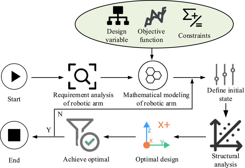
Figure 4. Process for optimizing and improving the structure of the robotic arm.
When optimizing the structure design of a robotic arm, its performance and strength should be maintained unchanged, and efforts should be made to reduce the self weight of the structure in order to improve the overall performance of the robotic arm. Firstly, a thorough analysis will be conducted on key parameters such as stress and strain of the robotic arm. These analyses are conducted under different operating conditions to gain a more comprehensive understanding of the performance of the robotic arm in various usage scenarios. The results of the analysis will help determine the design variables, which are the basis for optimization and improvement (Li et al., 2024; Zhang et al., 2024). The next step is to set the objective function, which is the core of optimization and improvement. The objective function is primarily aimed at reducing the weight of the robotic arm, while also considering other performance indicators such as stiffness and strength. The purpose of doing so is to make the structure of the robotic arm lighter, improve its usability and efficiency while meeting its functional requirements. After determining the objective function, a series of constraints need to be set. These constraints include material selection, allowable manufacturing errors, cost limitations, etc. After all these preparations are completed, the structure of the robotic arm is optimized and improved using Finite Element Analysis (FEA), topology optimization, and other methods. This process will go through multiple iterations and adjustments until the optimal solution is found (Zheng et al., 2023; Liu et al., 2022; Lin et al., 2023). The design variables are represented as shown in Equation 6.
In Equation 6, the width and height of the flipping arm are
In Equation 7, the quantity of all units is
The FEA of MFRA usually includes three steps: pre-processing, solving calculation, and post-processing. Among them, pre-processing involves establishing a finite element model and importing it into Ansys software for processing. In the calculation stage, the FEA model needs to be meshed first, dividing the model into multiple small elements for subsequent computational analysis. The next step is to apply corresponding boundary conditions and loads to the model based on the actual working conditions and material properties of the robotic arm, and then perform calculations on the model. During the calculation process, Ansys will automatically calculate the mechanical properties and performance indicators of the robotic arm based on the stress, strain, and other parameters of the unit. In the post-processing stage, Ansys software generates various visualization results for engineers to evaluate and optimize the performance of the robotic arm. These results include stress cloud maps, displacement maps, and stress maps. These visualization results intuitively display the stress distribution of the robotic arm in various parts, identify potential stress concentration and fatigue damage areas, and optimize the design of the robotic arm accordingly. Table 1 shows the performance parameters of the material.
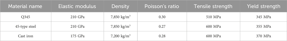
Table 1. Definition of material performance parameters.
When constructing the robotic arm model, this study uses hexahedral mesh to partition some of the robotic arms. The grid size is set to 10 mm, while other components use a 20 mm tetrahedral grid. To deal with the small features of each component, some rounded corners are eliminated, simplifying the drawing of smaller surfaces. At the same time, the influence of the existence of segmentation edges on the grid seed layout is addressed. Table 2 shows the specific content of the FEA model.
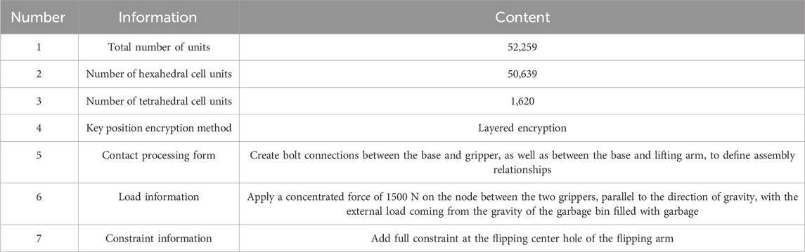
Table 2. Specific information of finite element model.
At the transition of the grid, a smooth transition method is chosen, and the key parts are subjected to grid refinement to ensure the quality of the model. Assuming the trash can is full, the total gravity is 1500 N. The deformation and stress cloud maps of the robotic arm under different states are shown in Figure 5.
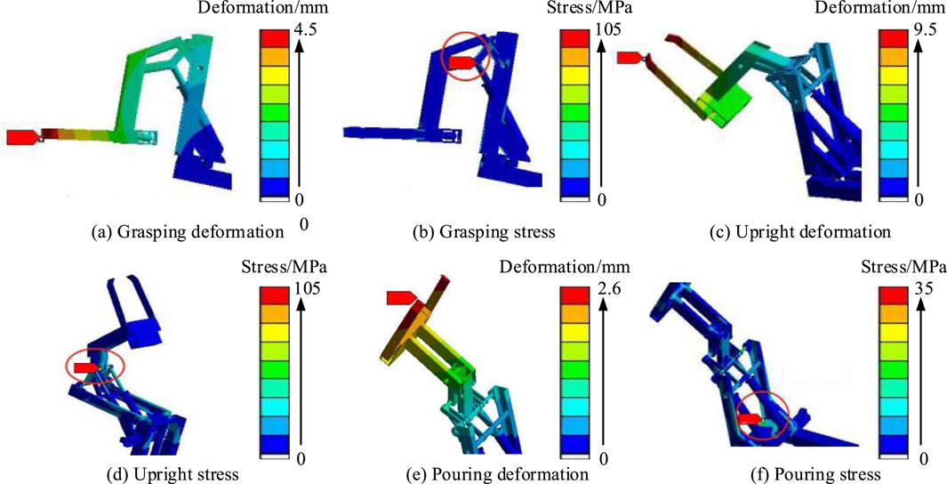
Figure 5. Deformation and stress cloud map of the robotic arm.
Figure 5A shows the deformation cloud map of the grasping state. The maximum deformation occurs at the front end of the gripper, approximately 4.28 mm. The deformation of the fixed end of the robotic arm is relatively small, about 0.45 mm. During the grasping process, the front end of the gripper needs to withstand a large force to clamp the object, resulting in significant deformation. Figure 5B shows the stress cloud map during the grasping process. The maximum stress occurs at the connection between the lifting arm corner and the cylinder piston, with a stress value of 102.86 MPa. Due to the piston pushing forward on the connecting shaft of the lifting arm during the process of grabbing the bucket, the stress value at this connecting shaft reaches its maximum. Figure 5C shows the deformation cloud map of the jerk state. The maximum deformation occurs at the gripper, approximately 9.43 mm. During the process of lifting the bucket with the robotic arm, due to the maximum distance between one end of the gripper and the flipping center of the rotating arm, the force arm value reaches its maximum, thus bearing the maximum torque value, resulting in significant deformation of the main body. Figure 5D shows the stress cloud map of the clean and jerk state. The location where the maximum stress occurs is the same as the grasping state, with a stress value of 104.61 MPa. Figure 5E shows the deformation cloud map in the tilted state. The maximum deformation occurs at the front end of the gripper, with a deformation value of 2.54 mm. The deformation amount is smaller than that in the grasping and lifting states, because during the tilting process, the main body bearing the load is the entire robotic arm. Figure 5F shows the stress cloud map in the tilted state. The maximum stress value occurs at the connection of the base, with a stress value of 33.32 MPa. Due to the tilting state, the component of the load force in the direction of the square tube increases, while the load force perpendicular to the square tube decreases, resulting in a decrease in the torque generated at the connection and a decrease in the stress value. Analysis shows that under different working conditions, the maximum stress value of the robotic arm is lower than the yield strength of the material 45 steel used for its connecting shaft, indicating that the structural design of the robotic arm is safe and reliable. However, in the tilted state, stress concentration occurs at the connection between the robotic arm and the base, and it is necessary to consider strengthening the connection treatment to improve its stability. In addition, to reduce overall costs, consideration has been given to replacing materials and reducing some usage.
To conduct motion and dynamic analysis of the MFRA of the garbage truck, Adams software is used for virtual prototype modeling and simulation in the experiment. The experimental steps mainly involve the horizontal return of the robotic arm, XY direction movement, gripper contraction, garbage bin lifting, telescopic direction return, and drive of the lifting mechanism. It simulates actual motion by applying loads and their driving functions to each component. Assuming the total gravity of the garbage bin is 1000 N. The motion state curve of the gripper is shown in Figure 6.
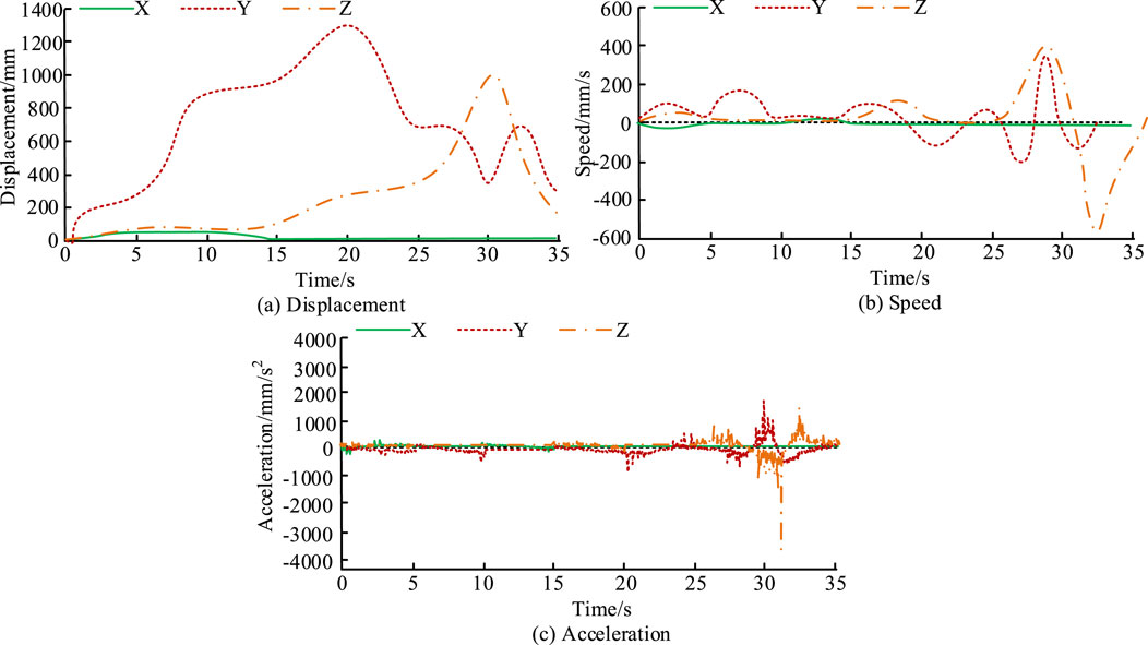
Figure 6. Gripper movement state curve.
Figure 6A shows the displacement curve of the gripper. The displacement in the X direction first increases and then decreases, increasing from 0 to 39 mm, and then decreases to 0 at the 15th s. The displacement in the Y direction reaches its maximum value of 1300 mm at the 20th s and returns to 0 at the 35th s. The displacement in the Z direction reaches its maximum value of 1000 mm at 30 s and 500 mm at 35 s. Figure 6B shows the gripper speed curve. The speed in the X direction first increases in reverse to 11 mm/s, decreases to 0 at the 5 s, gradually increases from the 10th s, reaches the maximum forward speed of 11 mm/s at the 13th s, and then decreases to 0 at the 15th s. The speed in the Y direction shows multiple peaks, with the maximum value occurring at the 31st s, and the speed is 346 mm/s. The speed in the Z direction also has multiple fluctuation segments, with the maximum value occurring at the 32 nd s and a speed of 552 mm/s Figure 6C shows the acceleration curve of the gripper. The acceleration in the X direction fluctuates within the range of −45 mm/s2 to 35 mm/s2, while the maximum acceleration in the Y direction is 1500 mm/s2, which occurs at the 30th s. The acceleration in the Z direction mainly fluctuates during the period of 25 s–35 s, with a maximum acceleration of 3500 mm/s2. Research has found that the displacement of the gripper in the Y-axis direction shows a trend of first increasing, then decreasing, and then increasing again, with speed fluctuating in multiple intervals. The displacement, speed, and acceleration changes in the Z-axis direction are relatively stable. In addition, the movement in the X-axis direction is relatively stable and can be directly controlled through a driving function, thereby achieving accurate grabbing of the trash can. The above indicates that by controlling the movement in the X-axis direction, direct control of the gripper can be achieved, and the opening and closing of the gripper can be controlled in a fixed and quantitative manner, thereby achieving accurate grasping of the garbage bin. The motion state curve of the telescopic and flipping mechanism is shown in Figure 7.
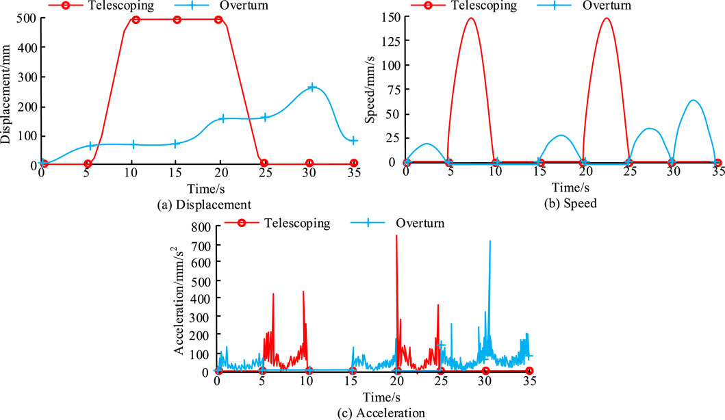
Figure 7. Motion state curve of the telescopic and flipping mechanism.
Figure 7A shows the displacement curve of the mechanism. The displacement of the telescopic mechanism increases from 0 to 500 mm, and then returns to 0 at the 25th s. The displacement of the flipping mechanism increases from 0 to 270 mm, and then decreases to 70 mm at the 35th s. Figure 7B shows the speed curve of the mechanism. The speed of the telescopic mechanism shows periodic changes, reaching a maximum of 150 mm/s at 7.5 s and 22.5 s. The speed of the flipping mechanism exhibits a quasi periodic variation, reaching a maximum value of 65 mm/s at 32.5 s. Figure 7C shows the acceleration curve of the mechanism. The acceleration of the telescopic mechanism corresponds to the speed and exhibits the same periodic variation, fluctuating within the range of [5s, 10s] and [20s, 25s]. The acceleration fluctuation time range of the flipping mechanism corresponds to the speed, reaching a maximum value of 260 mm/s2 around the 31st s. This discovery suggests that timed and quantitative process control can be achieved by adjusting the values of the driving function. The movement of the telescopic mechanism is mainly controlled by the driving function to extend and retract the hydraulic rod. By automatically and manually controlling the numerical value of the driving function, precise positioning of the device can be achieved. The force curve of the robotic arm is shown in Figure 8.
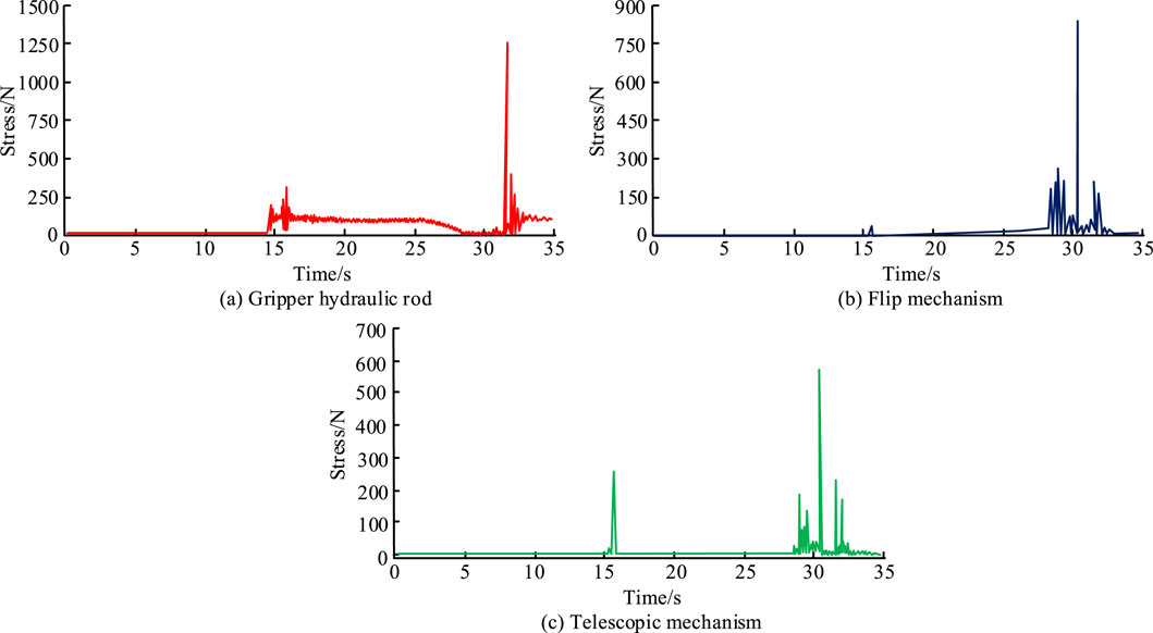
Figure 8. Force curve of robotic arm.
Figure 8A shows the force curve of the hydraulic rod of the gripper. During the dumping process of the garbage bin, the force curve of the hydraulic rod of the gripper shows a significant peak change. The maximum peak occurs at the moment when the garbage can is completely emptied, with an impact force of 1250 N. Through calculation, it is found that the stress generated at this time is about 168.37 MPa, which is lower than the allowable stress value of 345 MPa for the material. Therefore, this design meets the requirements for dynamic load use. Figure 8B shows the force curve of the flipping mechanism. In the first 15 s, the force on the flipping mechanism is almost zero, and then at 16 s, the force rapidly increases to around 45 N due to the gravity of the trash can. Then, there is a jump in stress before and after 30 s, which is caused by the dumping of the garbage bin. The stress value of the hydraulic rod for lifting is 171.21 MPa, which is lower than the yield strength of Q345 at 345 MPa, meeting the requirements for dynamic load. Figure 8C shows the force curve of the telescopic mechanism. The telescopic mechanism mainly bears impact loads during the gripping and dumping stages of garbage collection and transportation. During the gripping phase of around 16 s, due to the garbage bin being grabbed by the gripper, the telescopic mechanism bears the weight brought by the garbage bin, with a load impact amplitude of approximately 280 N. However, after the trash can was completely grabbed, the impact disappeared. When the trash can is overturned and returned to its original position, it also bears the impact of the load, with a maximum value of 590 N. Through calculation, the stress value of the telescopic hydraulic rod is 182.37 MPa, which is lower than the yield strength of Q345 at 345 MPa and meets the requirements of dynamic load.
The experiment is based on finite element and dynamic analysis of the robotic arm to optimize and improve its structure. The objective function variation curve and size optimization results are shown in Figure 9.

Figure 9. Objective function variation curve and size optimization results.
Figure 9A shows the variation curve of the objective function. After the 11th optimization, the objective function, which is the overall mass, reached its minimum value of approximately 64.39 kg, a decrease of about 14.28% compared to the initial 75.21 kg. Figure 9B shows the size optimization results. Compared to the size before optimization, the dimensions of the design variables have decreased. Before and after optimization, the thickness of the flipping arm is 49 mm and 44mm, and the height of the flipping arm is 85mm and 80 mm. The outer diameter of the hydraulic cylinder is 70 mm and 67 mm, the thickness of the hydraulic cylinder base is 30 mm and 28 mm, and the thickness of the hydraulic cylinder piston base is 30 and 28 mm. This indicates that through optimized design, the size of the robotic arm has been reduced, especially in terms of the thickness and height of the flipping arm. This indicates that the optimized design not only meets the usage requirements but also achieves the optimization objectives. The optimized structure has undergone some changes in stress distribution, but still meets the requirements for strength and stiffness. The experiment further considers manufacturing and processing factors, mainly involving parameters such as machining accuracy, material cutting performance, and mold complexity. Table 3 compares the manufacturing and processing factors before and after optimization.
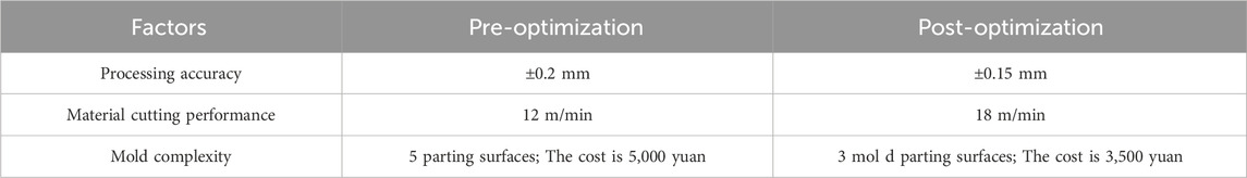
Table 3. Comparison results of manufacturing and processing factors before and after optimization.
In Table 3, before optimization, due to the complex structure, the machining accuracy requirements for each component were high, and the machining difficulty is high, with an average machining error of ±0.2 mm. After optimization, by simplifying some structures and adjusting dimensions, the machining accuracy requirements are appropriately reduced, and the average machining error can be controlled within ±0.15 mm, which is conducive to improving machining efficiency and reducing scrap rates. In the original design, some materials have fast tool wear and limited cutting speed during cutting. After optimization, while ensuring strength, some non critical parts are made of materials that are easier to cut or the heat treatment process of the materials is improved. Part of the structure uses improved Q345 material, which can increase the cutting speed by about 20% compared to before optimization. For some components that require mold forming, the mold design before optimization is complex and the manufacturing cost is high. For example, the mold for the flip arm, due to its special shape and size, requires five parting surfaces to manufacture, with a cost of up to 5,000 yuan. After optimization, the size of the flipping arm is adjusted, reducing the number of mold parting surfaces to three and lowering the mold cost to 3,500 yuan. At the same time, demolding is easier and the production cycle is shortened by about 30%.
This study aimed at the design problem of MFRA for garbage trucks, developed a robotic arm scheme, and then created a three-dimensional geometric model of the robotic arm using SolidWorks, and conducted motion mechanics analysis. During the structural optimization design phase, key parameters such as stress and strain of the robotic arm were analyzed in depth, and objective functions and constraints were set to optimize and improve the structure of the robotic arm. In the experiment, the maximum deformation of the grasping state occurred at the front end of the gripper, about 4.28 mm. The maximum stress occurred at the connection between the lifting arm corner and the cylinder piston, with a stress value of 102.86 MPa, which was lower than the yield strength of the material used, 45-type steel. The optimized structure of the robotic arm has achieved significant improvements in quality, size, and stress distribution. Specifically, the optimized robotic arm has reduced its weight by about 14.3%, and the thickness and height of the flipping arm have decreased by about 14.3% and 7.1%. The outer diameter and base thickness of the hydraulic cylinder decreased by about 7.1% and 5.0%, and the thickness of the hydraulic cylinder piston base decreased by about 7.1%. The overall weight of the robotic arm has been reduced to about 64.39 kg, a decrease of about 14.28%. The size of components such as the flipping arm was reduced, and after optimization, the machining accuracy and material cutting performance were improved, while the complexity of the mold was reduced. The average processing error was controlled within ±0.15 mm, the cutting speed of some materials has been increased by about 20%, the mold cost has been reduced to 3,500 yuan, and the production cycle has been shortened by about 30%. At the same time, the optimized structure has undergone changes in stress distribution. Although the maximum stress has decreased, the stresses at other locations are within the allowable stress range of the material, meeting the requirements for strength and stiffness. Research has shown that this design method has significant effects in improving the MFRA performance of garbage trucks, reducing structural weight, and optimizing processing. Compared with the existing research results, this study shows significant advantages through the systematic study of the multi-functional manipulator of garbage trucks from program formulation, motion mechanics analysis to structural optimization design. In terms of performance, the quality of the manipulator is reduced, the size of the key components is reduced, the processing accuracy is improved, the material cutting performance is improved and the mold complexity is reduced, which effectively improves the production efficiency and reduces the cost. However, most studies only focus on the improvement of a certain link of the manipulator, and lack of comprehensive and in-depth systematic optimization. However, the limitation of this research method is that in the actual complex garbage collection environment, the manipulator may face unexpected situations beyond the scope of experimental simulation, such as extremely diverse garbage types and extremely limited environmental space, which makes it difficult to give full play to some optimization effects. In future work, the control algorithm can be further optimized to improve the robot’s adaptive ability to complex environments, so that it can complete the garbage grabbing task more accurately and efficiently. Further reduce the failure rate of the manipulator under long-term high-intensity operation, and how to better achieve collaborative work with other systems of the garbage truck to improve the overall garbage collection and transportation efficiency, and promote the development of the multifunctional robot of the garbage truck to a more intelligent, efficient and reliable direction.
The original contributions presented in the study are included in the article/supplementary material, further inquiries can be directed to the corresponding authors.
HL: Formal Analysis, Investigation, Validation, Writing – original draft. YL: Methodology, Project administration, Writing – review and editing.
The author(s) declare that no financial support was received for the research and/or publication of this article.
The authors declare that the research was conducted in the absence of any commercial or financial relationships that could be construed as a potential conflict of interest.
The authors declare that no Generative AI was used in the creation of this manuscript.
All claims expressed in this article are solely those of the authors and do not necessarily represent those of their affiliated organizations, or those of the publisher, the editors and the reviewers. Any product that may be evaluated in this article, or claim that may be made by its manufacturer, is not guaranteed or endorsed by the publisher.
Alshihabi, M., Ozkahraman, M., and Kayacan, M. Y. (2024). Enhancing the reliability of a robotic arm through lightweighting and vibration control with modal analysis and topology optimization. Mech. Based Des. Struct. Mach. 1 (1), 1950–1974. doi:10.1080/15397734.2024.2400207
Aqib, M., Imran, A., Khan, K., Arsalan, M., Manzoor, S., Long, K., et al. (2024). Design and implementation of shape-adaptive and multifunctional robotic gripper. J. Field Robotics 41 (1), 162–178. doi:10.1002/rob.22251
Bogrekci, I., Demircioglu, P., Sasmaz, M. E., and Unal, C. (2024). Enhancing steel wheel ventilation efficiency through multi-objective optimization. Arabian J. Sci. Eng. 1 (1), 11661–11682. doi:10.1007/s13369-024-08708-0
Ding, L., Niu, L., Su, Y., Yang, H., Liu, G., Gao, H., et al. (2022). Dynamic finite element modeling and simulation of soft robots. Chin. J. Mech. Eng. 35 (1), 24–34. doi:10.1186/s10033-022-00701-8
Koti, V., Hampali, C., and Jagadeeshwaran, N. (2022). Dynamic analysis of flexible two link robotic arm considering joint stiffness. J. Mines. Metals. Fuels. 1 (1), 457–465. doi:10.18311/jmmf/2022/32950
Kouritem, S. A., Abouheaf, M. I., Nahas, N., and Hassan, M. (2022). A multi-objective optimization design of industrial robot arms. Alexandria Eng. J. 61 (12), 12847–12867. doi:10.1016/j.aej.2022.06.052
Li, W., Hu, Y., Zhou, Y., and Pham, D. T. (2024). Safe human–robot collaboration for industrial settings: a survey. J. Intelligent Manuf. 35 (5), 2235–2261. doi:10.1007/s10845-023-02159-4
Lin, Y., Xu, Y. X., and Juang, J. Y. (2023). Single-actuator soft robot for in-pipe crawling. Soft Robot. 10 (1), 174–186. doi:10.1089/soro.2021.0220
Liu, C. H., Chen, L. J., Chi, J. C., and Wu, J. Y. (2022). Topology optimization design and experiment of a soft pneumatic bending actuator for grasping applications. IEEE Robotics Automation Lett. 7 (2), 2086–2093. doi:10.1109/lra.2022.3142910
Liu, Y., and Wang, J. (2023). Spatiotemporal patterns and drivers of carbon emissions from municipal solid waste treatment in China. Waste Manag. 168 (1), 1–13. doi:10.1016/j.wasman.2023.05.043
Meng, H., Yang, K., Zhou, L., Shi, Y., Cai, S., and Bao, G. (2024). Optimal design of linkage-driven underactuated hand for precise pinching and powerful grasping. IEEE Robotics Automation Lett. 9 (4), 3475–3482. doi:10.1109/lra.2024.3369941
Parra, R. A., Fan, D., Jenett, B., del Águila Ferrandis, J., Tourlomousis, F., Abdel-Rahman, A., et al. (2023). Modular morphing lattices for large-scale underwater continuum robotic structures. Soft Robot. 10 (4), 724–736. doi:10.1089/soro.2022.0117
Peng, J., Haoxuan, W. U., Liu, T., and Han, Y. (2023). Workspace, stiffness analysis and design optimization of coupled active-passive multilink cable-driven space robots for on-orbit services. Chin. J. Aeronautics 36 (2), 402–416. doi:10.1016/j.cja.2022.03.001
Seguin, P., Preault, C., Bidaud, P., and Gazeau, J. P. (2023). From specialized industrial grippers to flexible grippers: issues for grasping and dexterous manipulation. Found. Trends® Robotics 11 (1), 1–89. doi:10.1561/2300000074
Srinivas, G. L., Javed, A., and Faller, L. M. (2024). Versatile 3D-printed fin-ray effect soft robotic fingers: lightweight optimization and performance analysis. J. Braz. Soc. Mech. Sci. Eng. 46 (6), 382–397. doi:10.1007/s40430-024-04957-0
Sun, Y., Zong, C., Pancheri, F., Chen, T., and Lueth, T. C. (2023). Design of topology optimized compliant legs for bio-inspired quadruped robots. Sci. Rep. 13 (1), 4875–4896. doi:10.1038/s41598-023-32106-5
Sundaralingam, S., and Ramanathan, N. (2023). A deep learning-based approach to segregate solid waste generated in residential areas. Eng. Technol. and Appl. Sci. Res. 13 (2), 10439–10446. doi:10.48084/etasr.5716
Tang, L., and Xie, B. (2023). Review on research progress of flexible soft manipulator. Recent Pat. Eng. 17 (3), 1–11. doi:10.2174/1872212117666220827151639
Zhang, K., Lammers, K., Chu, P., Li, Z., and Lu, R. (2024). An automated apple harvesting robot-from system design to field evaluation. J. Field Robotics 41 (7), 2384–2400. doi:10.1002/rob.22268
Zhang, P., Chen, W., and Tang, B. (2022). Design and feasibility tests of a lightweight soft gripper for compliant and flexible envelope grasping. Soft Robot. 9 (2), 376–385. doi:10.1089/soro.2020.0156
Zhao, Z., and Zhang, X. S. (2023). Encoding reprogrammable properties into magneto-mechanical materials via topology optimization. npj Comput. Mater. 9 (1), 57–73. doi:10.1038/s41524-023-00980-2
Keywords: garbage truck, multi-functional robotic arm, finite element method, structural optimization, stress, size
Citation: Li H and Li Y (2025) Finite element analysis and structural optimization design of multifunctional robotic arm for garbage truck. Front. Mech. Eng. 11:1543967. doi: 10.3389/fmech.2025.1543967
Received: 12 December 2024; Accepted: 17 March 2025;
Published: 02 April 2025.
Edited by:
Georgios Mavropoulos, School of Pedagogical and Technological Education, GreeceReviewed by:
Lu Zhang, Zibo Vocational Institute, ChinaCopyright © 2025 Li and Li. This is an open-access article distributed under the terms of the Creative Commons Attribution License (CC BY). The use, distribution or reproduction in other forums is permitted, provided the original author(s) and the copyright owner(s) are credited and that the original publication in this journal is cited, in accordance with accepted academic practice. No use, distribution or reproduction is permitted which does not comply with these terms.
*Correspondence: Yang Li, MTg4MTA2MzQzNjBAMTYzLmNvbQ==
Disclaimer: All claims expressed in this article are solely those of the authors and do not necessarily represent those of their affiliated organizations, or those of the publisher, the editors and the reviewers. Any product that may be evaluated in this article or claim that may be made by its manufacturer is not guaranteed or endorsed by the publisher.
Research integrity at Frontiers
Learn more about the work of our research integrity team to safeguard the quality of each article we publish.