 Wei Zhao
 Morten Kjeld Ebbesen
 Michael Rygaard Hansen
 Torben Ole Andersen2
94% of researchers rate our articles as excellent or good
Learn more about the work of our research integrity team to safeguard the quality of each article we publish.
Find out more
ORIGINAL RESEARCH article
Front. Mech. Eng., 04 February 2025
Sec. Mechatronics
Volume 11 - 2025 | https://doi.org/10.3389/fmech.2025.1535120
This article is part of the Research TopicEfficient energy utilization in hydraulic systemsView all 3 articles
This paper experimentally assess the energy consumption of a laboratory knuckle boom crane utilizing two proposed two-motor-two-pump (2M2P) motor-controlled hydraulic cylinders (MCC) in comparison to two conventional valve-controlled hydraulic cylinders (VCC). Experimental results demonstrate that using the motor-controlled crane instead of the valve-controlled crane results in 60%–64% total energy savings. In conclusion, this study highlights the practical suitability of the 2M2P MCCs for real-world applications, showcasing their enhanced energy efficiency compared to conventional VCCs.
Hydraulic cylinders are widely used in heavy-duty industries due to their inherent advantages, such as high power density, ability to withstand shock loads, and reliability in harsh operational conditions. In the past years, the valve-controlled hydraulic cylinder (VCC) circuits have been the standard and dominating the market. While VCCs are known for their simplicity, robustness, and mature technology, their energy efficiency is limited by throttling losses inherent in both the control and counterbalance valves. For instance, the efficiency of valve-controlled hydraulic cranes typically ranges from 8.5% for conventional systems to 27.3% for load-sensing valve-controlled systems (Liang et al., 1999). In excavators equipped with valve-controlled hydraulic systems, approximately 35% of the total input energy is consumed by the control valves (Zimmerman et al., 2007).
Given the ongoing climate crisis, there is a growing recognition of the critical role energy efficiency plays. Various strategies to enhance the energy efficiency of valve-controlled hydraulic cylinder systems can be broadly categorized into two approaches: cylinder-side methods and control system side methods. Cylinder-side methods primarily focus on reducing the weight of hydraulic components by utilizing lightweight yet strong materials Lubecki et al. (2022). However, these solutions are predominantly suited for mobile applications. On the control system side, transitioning toward valve-less control systems has emerged as a promising approach to minimize valve throttling losses and significantly improve efficiency across a wider range of applications. This transition can be achieved by using a motor-controlled hydraulic cylinder (MCC), where a hydraulic cylinder is directly connected to fixed-displacement hydraulic pump(s) driven by electric servo motor(s). MCC enables manipulation of the hydraulic cylinder’s motion by controlling the angular velocity(s) of the electric servo motor(s). MCCs can be classified into different configurations depending on the number of electric servo motors and hydraulic pumps utilized (Zhao et al., 2022). The main configurations comprise one-motor-one-pump (1M1P), one-motor-two-pump (1M2P), and two-motor-two-pump (2M2P) MCCs, as depicted in Figure 1. The abbreviations, POCV and ISV, are pilot-operated check valve and inverse shuttle valve, respectively. Most MCCs are equipped with a hydro-pneumatic accumulator serving as a low-pressure reservoir. While such accumulators help reduce excess pressure in the hydraulic system, alleviate transients, and improve system energy efficiency Lubecki et al. (2022), their contribution is inherently limited. This limitation arises because the accumulator pressure cannot exceed the hydraulic pump housing pressure, thereby restricting its impact on the overall energy efficiency of MCCs.
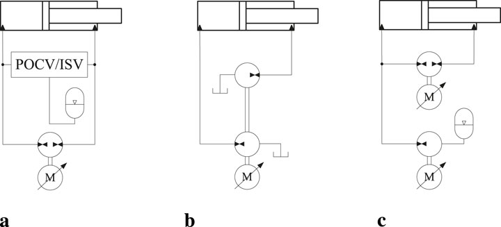
Figure 1. Main MCC topologies (Zhao et al., 2022). (A) 1M1P MCC. (B) 1M2P MCC. (C) 2M2P MCC.
Incorporating MCCs into applications at system level, particularly in cases involving multiple cylinders, is important for the energy efficiency. Notably, the deployment of three 1M1P MCCs on an industrial pipe-racking crane yielded a remarkable 83.4% reduction in energy consumption compared to the conventional valve-controlled system (Hagen et al., 2019b). The incorporation of six 1M1P MCCs into an excavator yielded energy savings of 47.8% compared to excavators equipped with VCCs (Ahn et al., 2011). Despite the good energy-saving performance of the 1M1P MCC, it requires a mechanism of two POCVs or an ISV, as illustrated in Figure 1A, to compensate for differential flow rates. However, this mechanism may induce system oscillations under specific operational conditions (Williamson and Ivantysynova, 2008). Furthermore, conventional 1M1P MCCs lack the capability to achieve system pressure control and an energy-efficient load-holding function to manage hose rupture situations.
The 1M2P MCC configuration, depicted in Figure 1B, eliminates the need for a flow rate compensation mechanism. Additionally, it demonstrates good energy efficiency performance compared to VCCs. For instance, according to the study in Zhang et al. (2017), an excavator powered by three 1M2P MCCs achieved a system efficiency of 73.3% within a given working cycle. However, the universal applicability of the 1M2P MCC is constrained by the requirement that the displacement ratio of the two pumps must align with the ratio of cylinder areas. It is important to note that an efficient method for implementing a passive load-holding function to address hose rupture situations in 1M2P MCCs has not yet been established.
The 2M2P MCC, as depicted in Figure 1C, eliminates the need for a mechanism to compensate for the cylinder differential flow rate. Moreover, unlike the 1M2P MCC, the 2M2P MCC does not require precise alignment between the pump displacement ratio and the cylinder area ratio. This system is also capable of maintaining accurate system pressure control and enabling an energy-efficient passive load-holding function, even in the event of a power failure (Ketelsen et al., 2020). Furthermore, the 2M2P MCC offers the advantages of cylinder velocity being insensitive to load pressure changes and the capability to amplify load pressure through pump revolution (Cho and Helduser, 2008). Despite these numerous advantages, the 2M2P MCC needs to demonstrate superior energy performance compared to the market-dominating VCC to achieve widespread industrial implementation. However, a comprehensive comparison of their energy efficiencies, particularly in multi-cylinder systems, has yet to be conducted.
This paper aims to fill the existing gap by conducting an experimental comparison of the energy efficiencies between a two-cylinder knuckle boom crane driven by 2M2P MCCs and VCCs under two distinct load cases.
The knuckle boom crane used in this study is shown in Figure 2. It is an HMF model 2020-K crane, situated within the laboratory facilities at the University of Agder. This crane is equipped with five hydraulic actuators originally driven by valve-controlled drives. However, for the purpose of this study, only the main and knuckle cylinders are considered. They are responsible for driving the crane arms in the plane of the crane.
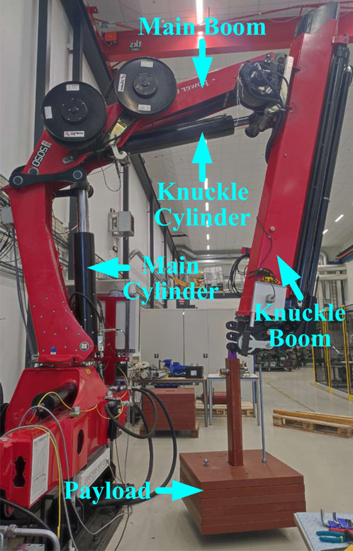
Figure 2. Knuckle boom crane.
The main boom of the crane has a length of 2,400 mm and a mass of 206.5 kg, while the knuckle boom measures 2,430 mm in length and has a mass of 841.4 kg. Both the main and knuckle cylinders feature identical rod diameters of 100 mm. However, they are distinguished by different bore diameters, with the main cylinder having a bore diameter of 160 mm, whereas the knuckle cylinder has a bore diameter of 150 mm. Additionally, the main cylinder has a stroke of 750 mm, while the knuckle cylinder has a stroke of 852.5 mm.
The valve-controlled drive circuits for the main and knuckle cylinders are shown in Figure 3. The constant high-pressure source (
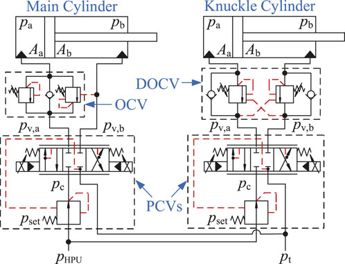
Figure 3. Valve-controlled drive system for the main and knuckle cylinders.
Figure 4A shows the hydraulic diagram of the proposed 2M2P MCC. This design is consistent with the 2M2P MCC used in a previous study (Zhao et al., 2023). The system consists of two fixed-displacement pump/motor units known as the main unit (
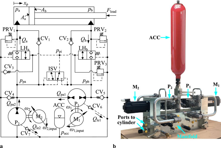
Figure 4. The proposed 2M2P MCC. (A) System architecture of the 2M2P MCC including variables used in the modeling. (B) 2M2P MCC prototype.
The system inputs consist of velocity inputs of
Integrating load-holding valves into the cylinder’s inlet and outlet is crucial in applications involving overrunning external loads to prevent load drop during critical situations such as power blackouts and hose ruptures. The
The prototype of the proposed 2M2P MCC is shown in Figure 4B. The major components used in the 2M2P MCC prototype, along with their respective parameters as provided by the manufacturers are listed in Table 1. The pressure and position transducers used in the motor-controlled cylinder drive are identical to those used in the valve-controlled cylinder drive. The angular velocities and torques of
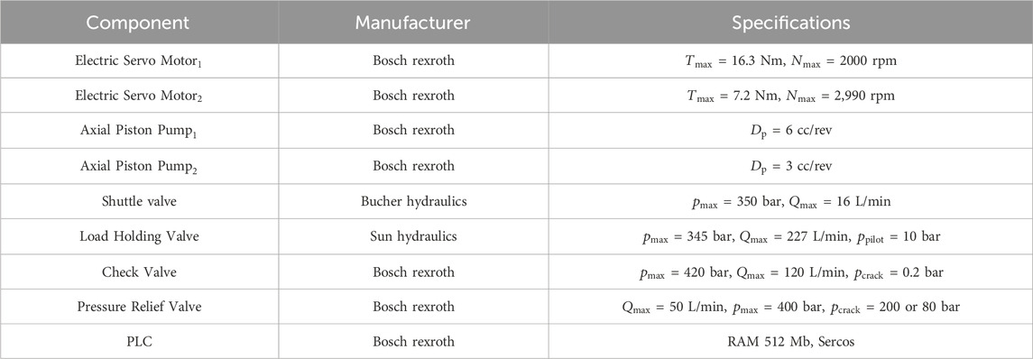
Table 1. Major components in 2M2P MCC.
Given the primary objective of this paper, which is to identify the differences in the energy efficiency performance between two different drive systems, further development of the control algorithm for the VCCs is not pursued. Instead, two Proportional-Integral (PI) controllers are employed to ensure the main and knuckle cylinders track the position reference signals reasonably accurate. The main cylinder’s PI controller is configured with a proportional gain of 4,000
The control algorithm, originally proposed for 2M2P MCCs in Zhao et al. (2023), is utilized in this study. Illustrated in Figure 5, this algorithm comprises four different control loops: the position control loop, cylinder pressure control loop, load-holding control loop, and pressure level control loop. Outputs from these loops are strategically selected by the mode and inputs selection module and subsequently integrated into the system. This approach ensures the realization of four-quadrant operation, passive load-holding functionality, and seamless transitions between these operational states. A comprehensive explanation of this control algorithm is available in (Zhao et al., 2023). Following verification via the simulation model, the control algorithm is implemented and tuned on the experimental setup. The PI controller gains in the four control loops are provided in Table 2. The cylinder pressure reference is set to 15 bar because the cracking pressure of valves
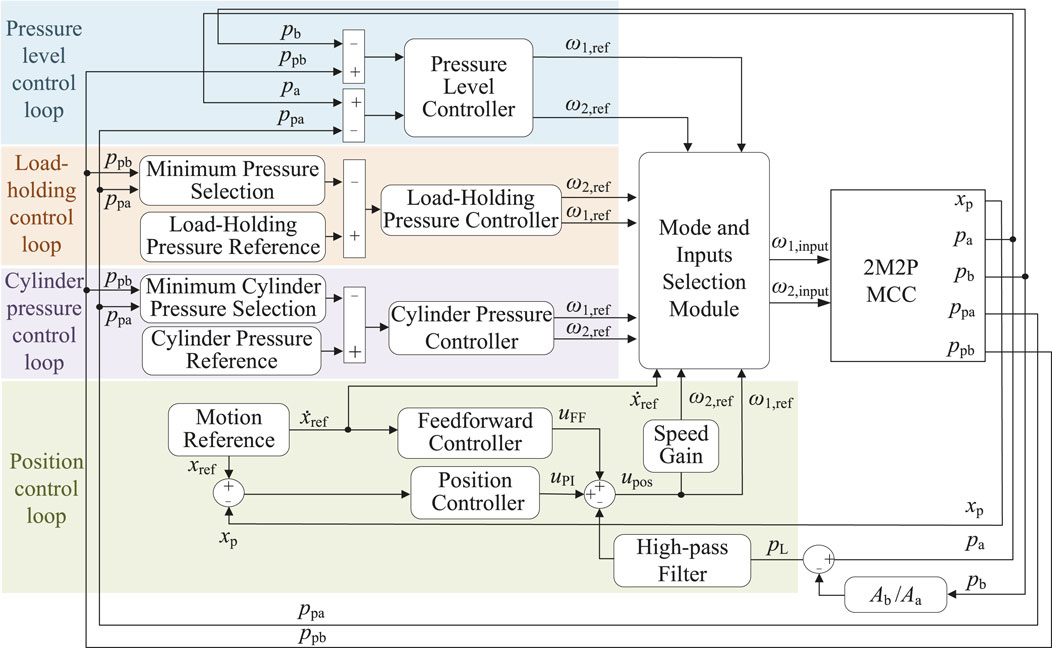
Figure 5. Illustration of the control algorithm (Zhao et al., 2023).
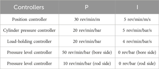
Table 2. Controller gains in the MCC control algorithm.
The crane path, depicted by the red trajectory in Figure 6, is designed to facilitate the movement of the crane while lifting a payload within the specified operational range outlined by the blue line. This path is carefully crafted, taking into account the constraints of the laboratory crane without triggering the saturation of
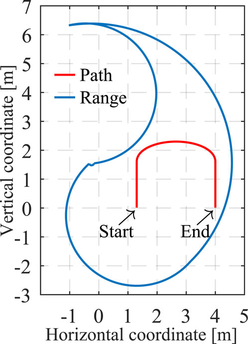
Figure 6. Crane operation range and generated path.
It is important to note that the knuckle boom crane was originally equipped with a valve-controlled drive system for both the main and knuckle cylinders. The 2M2P MCC prototype was utilized for both the main and knuckle cylinders, but not simultaneously, as only one prototype was available. For each load case, the crane was operated twice: first, with the prototype connected to the main cylinder while the valve-controlled system operated the knuckle cylinder, and second, with the prototype connected to the knuckle cylinder while the valve-controlled system operated the main cylinder. This approach ensured comprehensive testing of both configurations.
The position tracking performances of the two cylinders in the valve-controlled knuckle boom crane, across two load cases, are depicted in Figure 7. The reference signals for both the main and knuckle cylinders (denoted as “Ref” in the figures) are derived from inverse kinematic calculations based on the provided crane tip trajectory in Figure 6. “FB” denotes the feedback signal in the figures. Specifically, the knuckle cylinder retracts initially and extends after 42 s, while the main cylinder extends initially and retracts after 53 s. Both the main and knuckle cylinders closely follow the position references, with minimal deviation, as shown in Figures 7B, D. Notably, the tracking errors remain within acceptable limits across the two load cases. The knuckle cylinder exhibits tracking errors well within
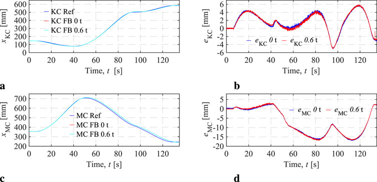
Figure 7. VCC knuckle cylinder (KC) and main cylinder (MC) position tracking performances. (A) KC position signals. (B) KC position tracking errors. (C) MC position signals. (D) MC position tracking errors.
It should be noted that the primary focus of this study is the comparison of energy performance, and therefore, advanced control algorithms for the VCCs were not investigated or applied. Despite this, the position tracking performance of the valve-controlled knuckle boom crane is considered acceptable for the purpose of assessing energy efficiency. However, the tracking errors observed could potentially be reduced with further effort on controller optimization.
The pressures of the knuckle and main cylinders in the valve-controlled crane are illustrated in Figure 8. The rod-side pressure is denoted as
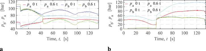
Figure 8. VCC KC and MC pressures. (A) KC bore-side and rod-side pressures. (B) MC bore-side and rod-side pressures.
In the experiments, as the crane follows an open path, the knuckle cylinder operates through the third, second, and first quadrants, exhibiting more complex pressure variations than the main cylinder. Notably, with a 0.6 t payload, the knuckle cylinder pressures intersect during directional changes, with the bore-side pressure consistently surpassing the rod-side pressure after the intersection. On the other hand, under a 0 t payload, there is no intersection; the rod-side pressure remains higher than the bore-side pressure. This occurs because the 0 t payload is insufficient to cause
The hydraulic power and cylinder mechanical power, along with the energy efficiencies of the two cylinders in the valve-controlled crane, are depicted in Figure 9. The cylinder mechanical power in VCCs, denoted as
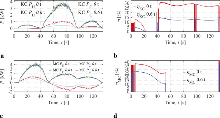
Figure 9. VCC KC and MC energy performances. (A) KC hydraulic and cylinder powers. (B) KC efficiencies in two load cases. (C) MC hydraulic and cylinder powers. (D) MC efficiencies in two load cases.
It can be seen that the input powers across two load cases for both the knuckle and main cylinders are identical, assuming negligible measurement noise. This is expected since the parameters
It should be noted that the VCC efficiencies observed in this study are relatively high compared to typical cases described in the literature (Liang et al., 1999; Love, 2012). This discrepancy arises because the energy losses of the lab’s HPU were not considered. The central HPU, which supports multiple hydraulic end users via a ring line system, consists of a pressure controlled variable-displacement pump, and a manually adjustable pressure setting of said pump. Calculating the HPU losses for the specific knuckle boom crane in this study is impractical. Therefore, the actual cylinder efficiencies, including the hydraulic power source, would likely be much lower than those observed above.
The position tracking performance of the two cylinders in the motor-controlled knuckle boom crane, across two load cases, is depicted in Figure 10. Both the main and knuckle cylinders exhibit precise tracking of the reference signal. The tracking error for the knuckle cylinder remains within
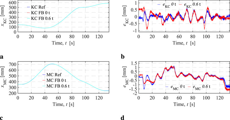
Figure 10. MCC KC and MC position tracking performances. (A) KC position signals. (B) KC position tracking errors. (C) MC position signals. (D) MC position tracking errors.
The cylinder pressures of the motor-controlled crane are depicted in Figure 11. It is observed that the minimum pressures in both the knuckle and main cylinders are well controlled at 15 bar during crane operations, demonstrating the pressure control capability of the 2M2P MCC. The knuckle cylinder pressures increase with the increasing load. Notably, for the motor-controlled main cylinder, the bore-side and rod-side pressures never intersect, and the bore-side pressure, which drives the load, increases with the increasing load. Overall, the cylinder pressure levels in MCCs are generally lower than those in VCCs across both load cases.
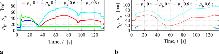
Figure 11. MCC KC and MC pressures. (A) KC bore-side and rod-side pressures. (B) MC bore-side and rod-side pressures.
The cylinder mechanical power in MCCs is also represented as
Figure 12 illustrates the energy performances of the motor-controlled knuckle and main cylinders. As shown in Figure 12A, the input power of the motor-controlled knuckle cylinder increases with the payload. Notably, during the lifting path, the motor-controlled knuckle cylinder operates without an energy regeneration mode, and its efficiencies across the two load cases are depicted in Figure 12B. These efficiencies, calculated using Equation 5, increase from approximately 25%–40% as the payload increases.
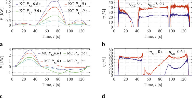
Figure 12. MCC KC and MC energy performances. (A) KC motor and cylinder powers. (B) KC efficiencies in the two load cases. (C) MC motor and cylinder powers. (D) MC efficiencies in two load cases.
As shown in Figure 12C, the motor-controlled main cylinder operates in two distinct modes, with a transition occurring around 50 s, where the cylinder output powers turn negative. In the energy consumption mode (positive output powers), input power increases with the payload. On the other hand, in the energy regeneration mode (negative output powers), input power decreases as the payload increases. Figure 12C illustrates the efficiencies of the motor-controlled main cylinder, which are calculated differently for each mode using Equation 9. In the third case of Equation 9, where
In Figure 12D, in energy consumption mode (before 50 s), the main cylinder’s efficiency with a 0.6 t payload is around 60%, slightly higher than the 50% efficiency observed with a 0 t payload. In energy regeneration mode, the efficiency with a 0.6 t payload reaches approximately 60%, significantly surpassing the 30% efficiency in the 0 t payload case. It is also noteworthy that energy regeneration in the 0.6 t payload begins around 50 s, whereas in the 0 t payload, it starts only after 86 s, due to the smaller load being insufficient to overcome initial system energy losses. It is important to note that the actual regenerative efficiencies would likely be lower than those observed above. An electric power storage device is missing in the experiments and therefore, the potentially regenerative power is dissipated by a resistor connected to the electric motor drive but in the analysis that power is considered 100% regenerated. It should be noted that energy flows into the accumulator during cylinder retraction and out of the accumulator during cylinder extension as the crane moves the payload along the desired path. However, since the accumulator pressure varies between 2 bar and 3 bar, these power contributions are negligible compared to
Compared to the VCCs in the valve-controlled crane, the MCCs in the motor-controlled crane demonstrate significantly higher energy efficiencies in energy consumption mode, even though HPU losses were not considered for the VCCs. Additionally, the VCCs lack energy regeneration capability, resulting in complete system energy loss when the output is negative. Therefore, the MCCs would substantially improve the overall energy utilization compared to VCCs.
The total energy consumed by the valve-controlled
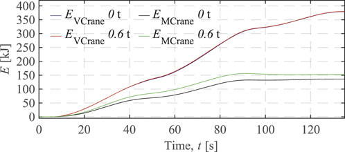
Figure 13. Total energies use by the valve-controlled crane and the motor controlled-crane.
For the MCCs, the total energy used increases with a greater payload. However, due to energy regeneration by the main cylinder, the total crane input energy remains almost steady at 0 t payload and decreases slightly with a 0.6 t payload after approximately 130 s. The final total energy used in the two load cases is 153 and 136 kJ, respectively. Consequently, in this study, using the motor-controlled crane instead of the valve-controlled crane results in 60%–64% total energy savings.
This paper addresses the comparison between valve-controlled hydraulic cylinder systems and two-motor-two-pump motor-controlled hydraulic systems. This type of comprehensive comparison has been performed for a real-life application characterized by:
• A knuckle boom crane, powered either by two valve-controlled hydraulic cylinders or by two two-motor-two-pump motor-controlled hydraulic cylinders, is employed in two distinct load cases.
• A specific crane lifting path is generated within the operational range of the crane to facilitate the experiment.
• The experimental results of the two systems, including position-tracking performance, cylinder pressures, and power and energy performance, are presented, compared, and analyzed in detail.
In conclusion, the two-motor-two-pump motor-controlled hydraulic knuckle boom crane demonstrates higher efficiency and better energy regeneration capabilities compared to its valve-controlled counterpart under the two loaded test cases. These improvements lead to notably lower energy consumption for the motor-controlled crane. This research serves as an example of experimental validation, highlighting the higher energy efficiency of this innovative hydraulic technology.
The raw data supporting the conclusions of this article will be made available by the authors, without undue reservation.
WZ: Conceptualization, Data curation, Formal Analysis, Investigation, Methodology, Software, Validation, Writing–original draft, Writing–review and editing. ME: Funding acquisition, Project administration, Supervision, Writing–review and editing. MH: Supervision, Writing–review and editing. TA: Supervision, Writing–review and editing.
The author(s) declare that financial support was received for the research, authorship, and/or publication of this article. This research was funded by the Research Council of Norway, SFI Offshore Mechatronics, project number 237896/O30. The article processing charges was funded by the University of Agder.
We would like to express our sincere gratitude to the following lab engineers for their invaluable assistance in building and testing the experimental setup: Jan Andreas Holm, Harald Sauvik, and Jan Christian Bjerke Strandene. Their expertise and willingness to help were instrumental in the successful completion of this project.
The authors declare that the research was conducted in the absence of any commercial or financial relationships that could be construed as a potential conflict of interest.
The author(s) declare that no Generative AI was used in the creation of this manuscript.
All claims expressed in this article are solely those of the authors and do not necessarily represent those of their affiliated organizations, or those of the publisher, the editors and the reviewers. Any product that may be evaluated in this article, or claim that may be made by its manufacturer, is not guaranteed or endorsed by the publisher.
Ahn, K. K., Yoon, J. I., and Truong, D. Q. (2011). “Design and verification of a new energy saving electric excavator,” in In the proceedings of the 28th international symposium on automation and robotics in construction (ISARC 2011). Editor S. Kwon (Seoul, Korea: International Association for Automation and Robotics in Construction IAARC), 259–264. doi:10.22260/ISARC2011/0046
Cho, S. H., and Helduser, S. (2008). Robust motion control of a clamp-cylinder for energy-saving injection moulding machines. J. Mech. Sci. Technol. 22, 2445–2453. doi:10.1007/s12206-008-0907-6
Hagen, D., Padovani, D., and Choux, M. (2019a). A comparison study of a novel self-contained electro-hydraulic cylinder versus a conventional valve-controlled actuator-part 2: energy efficiency. Actuators 8, 78. doi:10.3390/ACT8040078
Hagen, D., Padovani, D., and Choux, M. (2019b). Enabling energy savings in offshore mechatronic systems by using self-contained cylinders. Model. Identif. Control 40, 89–108. doi:10.4173/mic.2019.2.2
Ketelsen, S., Andersen, T. O., Ebbesen, M. K., and Schmidt, L. (2020). A self-contained cylinder drive with indirectly controlled hydraulic lock. Model. Identif. Control 41, 185–205. doi:10.4173/mic.2020.3.4
Liang, X., Virvalo, T., and Linjama, M. (1999). “The influence of control valves on the efficiency of a hydraulic crane,” in The proceedings of the Sixth Scandinavian International Conference on Fluid Power, Tampere, Finland, May 26 - 28, 1999, 381–394.
Love, L. J. (2012). Estimating the impact (energy, emissions and economics) of the us fluid power industry. Oak Ridge Natl. Lab. doi:10.2172/1061537
Lubecki, M., Stosiak, M., Skačkauskas, P., Karpenko, M., Deptuła, A., and Urbanowicz, K. (2022). Development of composite hydraulic actuators: a review. Actuators 11, 365. doi:10.3390/act11120365
Williamson, C., and Ivantysynova, M. (2008). “Pump mode prediction for four-quadrant velocity control of valueless hydraulic actuators,” in The proceedings of JFPS International Symposium on Fluid Power, Toyama, Japan, 323–328. doi:10.5739/isfp.2008.323
Zhang, S., Minav, T., and Pietola, M. (2017). “Decentralized hydraulics for micro excavator,” in The proceedings of the 15th Scandinavian International Conference on Fluid Power, Linköping, Sweden, 187–195. doi:10.3384/ecp17144187
Zhao, W., Bhola, M., Ebbesen, M. K., and Andersen, T. O. (2023). A novel control design for realizing passive load-holding function on a two-motor-two-pump motor-controlled hydraulic cylinder. Model. Identif. Control 44, 125–139. doi:10.4173/mic.2023.3.3
Zhao, W., Ebbesen, M. K., and Andersen, T. O. (2022). “Identifying the future research trend for using speed-controlled hydraulic cylinders in offshore applications through literature survey,” in the proceedings of the 2022 IEEE Global Fluid Power Society PhD Symposium (presented), Naples, Italy.
Keywords: motor-controlled hydraulic cylinder, knuckle boom crane, valve-controlled hydraulic cylinder, hydraulic energy transmission, energy consumption
Citation: Zhao W, Ebbesen MK, Hansen MR and Andersen TO (2025) Experimental assessment of energy consumption: a comparative study between motor-controlled and valve-controlled cylinders in knuckle boom crane operations. Front. Mech. Eng. 11:1535120. doi: 10.3389/fmech.2025.1535120
Received: 26 November 2024; Accepted: 13 January 2025;
Published: 04 February 2025.
Edited by:
Liselott Ericson, Linköping University, SwedenReviewed by:
Samuel Kärnell, Linköping University, SwedenCopyright © 2025 Zhao, Ebbesen, Hansen and Andersen. This is an open-access article distributed under the terms of the Creative Commons Attribution License (CC BY). The use, distribution or reproduction in other forums is permitted, provided the original author(s) and the copyright owner(s) are credited and that the original publication in this journal is cited, in accordance with accepted academic practice. No use, distribution or reproduction is permitted which does not comply with these terms.
*Correspondence: Wei Zhao, d2VpLnpoYW9AdWlhLm5v
Disclaimer: All claims expressed in this article are solely those of the authors and do not necessarily represent those of their affiliated organizations, or those of the publisher, the editors and the reviewers. Any product that may be evaluated in this article or claim that may be made by its manufacturer is not guaranteed or endorsed by the publisher.
Research integrity at Frontiers
Learn more about the work of our research integrity team to safeguard the quality of each article we publish.