 Dipak S. Patil1Manmohan M. Bhoomkar1
 Neeraj Sunheriya2*
 Jayant Giri2,3,4
 Atul Kulkarni5Lalit N. Patil6Lalit K. Toke7
 Thanikodi Sathish8Mohammad Kanan9,10*
- 1Department of Mechanical Engineering, Pune Vidhyarthi Griha’s College of Engineering and Technology, Pune, Maharashtra, India
- 2Department of Mechanical Engineering, Yeshwantrao Chavan College of Engineering, Nagpur, Maharashtra, India
- 3Division of Research and Development, Lovely Professional University, Phagwara, Punjab, India
- 4Centre for Research Impact and Outcome, Chitkara University Institute of Engineering and Technology, Chitkara University, Rajpura, Punjab, India
- 5Department of Mechanical Engineering, Vishwakarma Institute of Information Technology, Pune, Maharashtra, India
- 6Department of Automation and Robotics, Dr. D. Y. Patil Institute of Technology, Pune, Maharashtra, India
- 7Department of Production Engineering, Shri Guru Gobind Singhji Institute of Engineering and Technology, Nanded, Maharashtra, India
- 8Saveetha School of Engineering, SIMATS, Chennai, Tamil Nadu, India
- 9Department of Industrial Engineering, College of Engineering, University of Business Technology, Jeddah, Saudi Arabia
- 10Department of Mechanical Engineering, College of Engineering, Zarqa University, Zarqa, Jordan
This study analyses the impact of process parameters on Glass Fiber Reinforced Polymer (GFRP) components produced through conventional drilling on a CNC drilling machine (VMC). GFRP’s challenging machinability is due to its high strength-to-weight ratio, durability, and customizable mechanical properties. The study aims to minimize kerf angles in drilled holes, identifying optimal parameter combinations based on Signal-to-Noise ratios. The best combination of parameters that used to reduce the value of the kerf angle was considered at 2,800 RPM spindle speed and 1,200 mm/rev feed rate. The experimental work reveals that the spindle speed significantly affects the kerf angle, while the feed rate and spindle speed both influence the variation in the kerf angle and show the best results at the ideal values of the two parameters. The study details an analysis of the process parameters of drilled holes on kerf angle in multiple holes in the specimen, applying Taguchi’s design of experiments and analysis of variance. Comparison of findings was made with existing literature on determination of the importance of spindle speed and feed rate for the determination of kerf angle. The best results were obtained when all these parameters set to the ideal values, where the minimum angular kerf of 0.1145° was observed.
1 Introduction
Conventional materials, i.e., metals or metallic alloys are being replaced by composite materials due to their advantages over conventional materials due to its advantages over other materials, fibre reinforced composites are used in several industrial applications (Müller and Monaghan, 2000; Patil et al., 2022; Prasad and Chaitanya, 2023). High fracture toughness, high heat and corrosion resistance, high durability, high resistance to wear, impact, and fire are only a few of these benefits (Hanifi et al., 2024; Lee et al., 2010). The numerous holes can be drilled under various machining circumstances using the conventional drilling process approach. Spindle speed and feed rate variation are machining conditions for the typical method while drilling holes. Some issues, such as fibre pull out and delamination, can arise in both conventional and non-conventional processes (Geier et al., 2023; Geier et al., 2019). Finding better machining techniques and machining settings is crucial (Tufail et al., 2024; Thakare et al., 2024).
Drilling procedures for fibre reinforced composites are commonly utilised in a wide range of industrial applications, including those in the civil construction, automotive, aerospace, and marine sectors (Jagadeesh et al., 2023; Rampal et al., 2022). To achieve high joint strength, holes in the material must be formed that are damage-free and precisely dimensional. As a result, it is crucial that the riveted or bolted joints utilised to assemble these composites have adequate strength. The quality of the hole drilled in the composite affects the joint’s strength (Kumar et al., 2023). In the present work, compression moulding and hand layup are both used to create composite material plates that are 8 mm thick and 300 mm by 300 mm in size (Goud et al., 2022).
The experimentation was conducted using Taguchi’s orthogonal array L16 (Adin and İşcan, 2022; Elizalde-González and García-Díaz, 2010). The mechanical properties’ measured values were then subjected to ANOVA for in-depth analysis (Narasimhamu et al., 2024; Kamble et al., 2024). The recommended parameter configurations for achieving the lowest kerf angle in GFRP components are depicted in Figure 1.
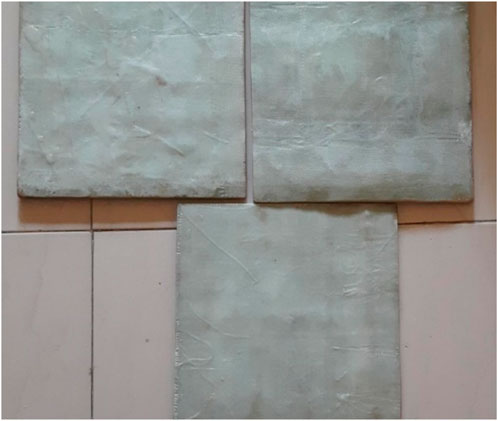
Figure 1. Work specimen sheets of Glass fibre reinforced polymer (GFRP).
The quality of drilled holes in aluminium alloys used in the aerospace industry is vital to ensure high-precision structural integrity. For this reason, selecting cost-effective cutting tools and cutting parameters is crucial (Adin, 2023a). Drilling is a common technique for creating holes in composites made of Glass Fibre Reinforced Polymer. Industrial drilling machines with manual controls or VMC machines are used to generate the holes (Raj and Karunamoorthy, 2016). When compared to manual control, VMC can be used to attain good accuracy and control. The quality of the hole determines how well a joint is riveted or bolted. Hence, the quality evaluation of the drilled holes becomes a vital step. Thus, it is required to study the output characteristics like drilled hole diameter, kerf ratio, circularity, and other; and quality holes produced by the variation of machining parameters with the help of standard and unconventional approaches.
Fiber epoxy composites are advanced materials consisting of fibers such as carbon, glass or aramid bonded together by an epoxy resin matrix. These composites have high strengths, stiffnesses, and low densities, so they find their major applications in the aerospace, automobile, marine, and sporting goods industries (Murgaiyan et al., 2024; Rajendran et al., 2024; Shanmugam et al., 2024). Fiber provides the basic strength and stiffness, whereas the epoxy resin acts as a binder that transfers loads between fibers and generally protects them from environmental degradation (Prashanth et al., 2017). The type, orientation, and the choice of resin may be varied to achieve different mechanical, thermal, and electrical properties (Saba et al., 2016). One of the primary advantages of fiber epoxy composites is that they have very high strength-to-weight ratio, making them strong yet lightweight. They also exhibit very good fatigue resistance, corrosion resistance, and dimensional stability. In layup, the fibers are impregnated with an epoxy resin that is cured later to form a solid part of composite. It is an effective technique for developing complex shapes and structures. Fiber epoxy composites have superior performance and are thus under continuous development for many applications (Wang et al., 2021). It has made composite materials one of the most transformative materials in modern engineering and manufacturing, providing extraordinary strength-to-weight ratios and corrosion resistance compared to traditional materials. Of these composites, GFE composites exhibit outstanding mechanical properties, which qualify them as an excellent candidate for any engineering application starting from aerospace and automotive industries to sporting goods and renewable energy technologies (Altin Karataş et al., 2020).
Researcher has used both natural and synthetic fibres as the reinforcing material. These strengthening constituents take a major role in carrying loads in FRP composites and are usually much stronger than the matrix materials (Lu et al., 2023). The FRP composite performance is influenced by several factors such as the properties of the fibres, fibre orientation and fibre shape and ratio of fibre volume to the matrix (Jagadeesh et al., 2023). The application of glass fibre-reinforced polymer into concrete has also shown high potential to become an alternate recycling technique, considering both financial and environmental factors (Tao et al., 2023; Yang et al., 2023). With the increasing demands for precision engineering in these sectors, the reliability and durability of mechanical connections become very important, and the accurate analysis of fundamental drilling processes presents a critical need (Geier et al., 2023). Some researchers focussed on the machinability of hybrid CFRP composites. In the research, CFRP composites containing 0 weight percent, 0.125 weight percent, 0.25 weight percent, and 0.375 weight percent of graphene nanoplatelets (GNPs) were manufactured by the hand layup method. Moreover, from the examination of the drilled surfaces, it is found that the virgin CFRP material exhibited more intense surface defects. These surface flaws appeared to be reduced with the incorporation of GNPs in the CFRP composite (Thakur and Singh, 2023). The choice of the material of the drill and the geometry of the drill greatly determines drilling performance in composites. Of recent, advanced tool materials used include polycrystalline diamond (PCD), coated carbide, and cubic boron nitride (CBN). The tool’s wear resistance and tool lifetime are improved by such a tool material during high-speed drilling. There is the improvement of thrust force and reduction of delamination while drilling because of introducing new geometries, such as step drills, helical drills (Duan et al., 2023; Nazir et al., 2023; Lin et al., 2024). For the purpose of simultaneously optimizing the design of fiber-reinforced composite laminates on several scales and materials, the MMCAP model was constructed by adapting the SIMP scheme for macroscopic topology and the DMO scheme for microscopic material selection (Duan et al., 2023). Optimization of drilling parameters in terms of spindle speed, feed rate, and drill diameter is crucial for hole-making operations in composite materials. State-of-the-art algorithms and statistical methods, such as RSM, Taguchi methods, and genetic algorithms have been used in the investigations to determine the optimum machining conditions. Additionally, multiple objectives have been considered while using optimization frameworks that tend to balance trade-offs, such as surface quality and tool wear against the time of machining (Hanifi et al., 2024; Lee et al., 2010; Geier et al., 2023; Geier et al., 2019; Jagadeesh et al., 2023).
In another effort, a developed extended three-dimensional transient fluid-structure interaction model was applied for numerical simulations. This was for evaluating the mechanisms leading to delamination and generation of geometric flaws around holes while drilling aerospace-grade multidirectional CFRP laminates autoclave cured. This is a common machining operation in composite structures for making holes for bolts or rivets (Nyaboro et al., 2020; Jeevi et al., 2019; Zeinedini et al., 2023). Nonetheless, in order to maintain the structural integrity of the composite, tight tolerances and geometric integrity are of paramount importance. A major problem resulting from drilling in composites is the generation of the taper angle formed along the hole walls, otherwise known as the kerf taper angle (Kumar and Kant, 2020). This deviation in the hole axis with respect to the ideal cylindrical geometry might reduce the load carrying capacity of the hole and possibly lead to the catastrophic failure of the overall structure. In mechanical micro-drilling, the tool is in direct contact with the composite material (Müller and Monaghan, 2000).
This direct contact causes some problems like tool wear, geometrical damages due to machining forces (e.g., delamination and fiber pull-out), and possibility of tool breakage. These factors collectively make the mechanical micro-drilling of fibrous composites a challenging task 6. The most critical material defect that exists in fibrous polymeric composites arises from the delamination caused by the drilling techniques (Lukács et al., 2023). The study in this work on the assessment of the kerf taper angle within holes conventionally drilled in GFE composites is a multi-disciplinary study that requires proper analysis and detailed research. The factors that affect the kerf taper angle include drilling parameters, material characteristics, and tool wear effects. An interaction among those variables results in complex drilling dynamics, which affect hole output quality. Some of the research activities aimed to understand the effect of process factors on kerf taper and to develop a prediction model for the results in AWJM of Kevlar epoxy composites. Four different process parameters, including water pressure, stand-off distance, traverse speed, and abrasive mass flow rate, were considered. The study finds that, of the process parameters, water pressure and cross-traverse speed prove to be the two most influential factors for determining the kerf lean angle (Dumbhare P et al., 2018; Shahrajabian and Farahnakian, 2013; Solati et al., 2019).
SEM was performed on the morphology of the laser-drilled holes to examine the drilling conditions. From the results obtained, when compared to traditional drill processes, it is shown that the correct conditions of laser drilling can add tensile strength and reduce the surface roughness of a drilled glass fiber-reinforced plastic laminate. Additionally, obtained results were treated by a multiresponse optimization strategy in order to accomplish maximum tensile strength, minimum heat-affected zone, reduced surface roughness, and minimized taper angle. It is therefore possible to determine the systematic evaluation of the kerf taper angles of conventionally drilled holes in GFE composites. By understanding the processes that lead to creating the kerf taper angle, researchers and engineers can develop effective means for minimizing adverse effects on the mechanical joint. The current work clarifies the interrelation between the drilling parameters, composite material properties, and resultant kerf taper angles by the optimal combination of experimental analysis and theoretical modeling. The current research deals with optimization of hole drilling processes in the case of GFE composites so as to improve the reliability and load-carrying capacity of mechanical joints. Thorough knowledge of the machining characteristics of composites can be considered as a sound basis for high performance of structures, since industries are heading toward exploiting more potential that composite materials have at their disposal.
Though much prior work has been conducted in analyzing the influence of machining parameters on the kerf taper angle of composite materials, there is still a big deficiency in understanding the detailed influence of these parameters on glass fiber epoxy composites. The existing studies mostly focus on metallic materials or general composite classifications without addressing the unique structural and thermal characteristics of glass fiber epoxy. There has been scant concern for the concurrent influence of spindle speed and feed rate on kerf taper, especially within traditional drilling techniques, which continue being widely used in most industry settings. This research aims at filling these gaps by methodically assessing the interrelation between machining parameters and kerf taper angle in glass fiber epoxy composites. This research will attempt to provide some practical insight into the improvement of drilling operations in high-performance composite environments using thorough statistical analysis and incorporating specific challenges, such as tool wear and material anisotropy. The work extends previous research findings but connects the empirical and theoretical knowledge needed for the proper machining of glass fiber epoxy composites.
2 Materials and methods
This composite material uses glass e-poxy resin. This Glass Fiber Epoxy is one of the commonly used materials in the aerospace and other industries due to its lightweight and high strength. Holes were drilled using HSS twist drill bits ranging from 1 mm up to 10 mm in diameter in this composite material. A variable speed settings bench drill press is used to drill the holes. The drill press was fitted with a depth stop, which ensured constant depth for all holes. A digital calliper is used for measuring the diameter of the drilled holes, and a protractor is used for measuring the kerf taper angle.
It is a statistically efficient design and reduces experimental runs while obtaining reliable estimation of main effects. The L16 array can accommodate up to 15 degrees of freedom which is necessary for your study’s factors, such as spindle speed and feed rate. The L16 array ensures unbiased independent testing of factors but will presume that higher-order interactions can be ignored. To gain reliability, replicates must be run to account for some variability and increase the power of the statistics. ANOVA established the results by looking to residual errors, and may require more runs if considerable interactions are expected. Overall the L16 design is robust when screening and optimizing, insofar as these considerations are held.
The specimen was prepared by cutting the glass fiber epoxy composite sheets into standard and rectangular specimens. Care was taken such that the specimens are free from any type of defect or surface irregularity and should be perfectly flat to eliminate any disturbances during the drilling process. The specimen was held firm on the drill press table by the aid of clamps to eliminate movements of the work material during the drilling operation. An appropriate size of drill bit was selected using the material whose diameter of the hole is to be made. The drill press speed was adjusted according to the manufacturer recommendation for drilling composites. A series of holes are drilled in the specimen, with one of the drilling parameters changed from the rest, such as speed, feed rate, or drill bit diameter. All holes are drilled to the same depth using the depth stop on the drill press. The specimen was retracted from the drill press after the drilling process. A protractor was used to measure this sidewall angle of the hole to the specimen surface. For the circumference of the hole, there might be a variation in the kerf taper angle, therefore the kerf taper angle has been measured at a few points around the circumference of the hole. The measured value of the kerf taper angle and some other relative parameters have been recorded for every drilled hole. The data were analyzed in order to find out the effect of drilling parameters on the kerf taper angle. First, calculate the average value of the kerf taper angle for each set of drilling parameters. Statistical analysis, such as analysis of variance (ANOVA), was performed to determine the significance of the observed differences in kerf taper angle.
In the present work, Vertical Machining Centre (VMC) has been used for making holes in working parts, as shown in Figure 2. The machine has a table size of 900 × 430 mm and stroke length of 560 × 410 × 460 mm on X, Y and Z-axis respectively. It is having automatic tool changer which has a minimum capacity of 20 tools. The VMC KODI 40 V55 model is working on FANUC CNC controller with minimum spindle speed up to 8,000 rpm. The VMC is having minimum power of 5.6 kw. For research work, carbide drill bit with 45° helix angle is used for making L16, i.e. 16 holes. GFRP sheet of 8 mm thick attached in the fixture for making 16 holes of 10 mm in specimen material is used for experimentation as shown in Figures 3, 4. The value for Relative Humidity was noted as 47%. The ambient temperature was noted as 39°C (Adin, 2023a).

Figure 2. Tool with work specimen.
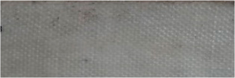
Figure 3. Sample sheet before drilling the holes.
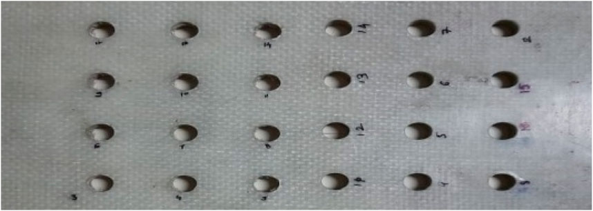
Figure 4. Sample sheet after drilling the holes.
Work piece specimen of GFRP sheet of 8 mm is attached and ready to machine to make right angle at corners then writing a VMC program and giving data point inputs with respect to centre of hole with mixing the position of plate using dial gauge as shown in Figure 2. Winding the center of the work piece using the display and control panel and lastly the program is feed into the machine for drilling process to start.
For this research experimentation, the sample or object consists of Glass Reinforced Epoxy (GRE), which falls under the category of fiber-reinforced plastics. This composite is comprised of an epoxy resin, employed as the primary polymer matrix, and is strengthened by glass fibers. The work piece or specimens are produced by hand layup processing method of different composite sheets and to make it single unit by compression modelling process. The composite work piece material consists of 35% glass fibre and type of polymer structure is Bidirectional (cloth matte) as typical properties of composite. Table 1 shows some typical properties of Work specimen. Table 2 depicts the mechanical properties of material.
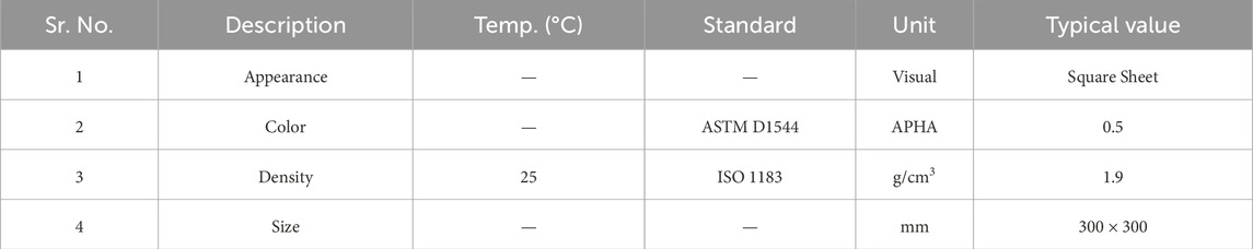
Table 1. Typical properties of work specimen.

Table 2. Mechanical properties of work Specimen.
For this study, the composite work specimen is manufactured as per the standard methods of GFRP preparation. It starts with initial step of applying wax polish to the mould then making sure the surface we polished is clean and smooth. Applying epoxy resin to the surface with the Cloth matte (surface matte) is applied. As after applying RP-10 matte oven rowing matte one by one with applying epoxy resin to matte then it needs to apply epoxy resin to 1:1 by hardener. Followed this process till we get required thickness i.e., 8 mm to achieve the thickness, it needs to keep it for drying around 7–8 h. The Important note is point-Mix resin and hardener kept for 5 min.
For the current investigation, four operational parameters have been chosen for testing, specifically thickness, kerf angle, Spindle Speed and Feed Rate. The process parameters and their corresponding settings are detailed in Table 3. The choice of these parameter levels and their ranges is informed by prior research and the operational limits of the machinery.
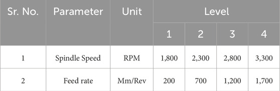
Table 3. Parameters and their levels.
To enhance result accuracy, the minimal set of experiments required to obtain the mean outcome value employs Taguchi’s orthogonal array L16 for experimental design. Consequently, a total of 16 specimens were manufactured, each involving adjustments to process parameters as outlined in the layout provided in Table 4.
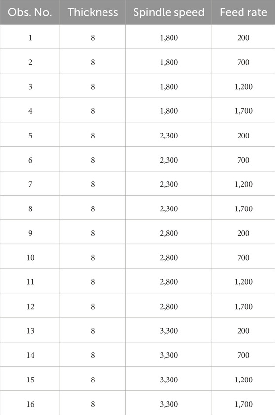
Table 4. Experimental design.
The spindle speed and feed rate for evaluating kerf taper angle in drilled holes of glass fiber epoxy composite were determined based on material properties, drill bit characteristics, and desired outcomes. Manufacturing requirements and past researcher guided the selection of spindle speed and feed rate. Statistical considerations ensured appropriate parameter variation for the study. The aim was to find spindle speed and feed rate combinations that minimize kerf taper angle and produce high-quality holes in the composite.
Entry and Exit Diameters of drilled holes are measured using three axis Spectra CMM (Coordinate Measuring Machine) which works on Arcocad Inspection software on which response characteristics kerf angle is measured by taking measurement of TKW and BKW of the drilled on 8 mm GFRP sheet as shown in Figure 5. The CMM machine having bed volume of 500 × 600 × 400 (cuboid) stroke length in X, Y and Z-axis respectively. The kerf angle is measured by CMM tool i.e., Renishaw MH20i Touch rigger ruby ball of 2 mm in diameter with angular scale with 2-micron accuracy as shown in Figure 6.
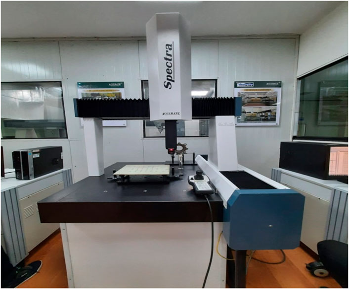
Figure 5. Tool with work specimen.
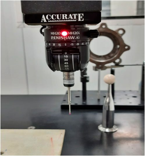
Figure 6. Measurement of kerf angle.
Arcocad software was used to collect the data. The probe was employed to touch the plate’s four corners, thereby establishing a reference plane within the software. It was proceeded to adjust this plane by the designated plate thickness to create a second plane. Subsequently, measurement path was determined and accordingly navigated to the first hole, selecting four points on its front side. The procedure was repeated for the hole, lowering the probe’s height by the plate’s thickness to capture four points on the back side and determine its diameter (probe controlled by the controller). This methodology was carried out for the remaining holes based on the predetermined path. Throughout this process, all data points were recorded in the software. The collected data was transferred into the software. Subsequently, within the software interface, specify the attribute to be measured using the gathered data points. Input the baseline characteristic and define the permissible tolerance range for the value.
3 Results and discussion
The kerf angle measurements for each individual experiment are presented in Table 5. The mean, standard deviation, and error margins of kerf angle measurements were considered. The overall average of the observations calculated as mean kerf angle was given by 2.0095°. This result gives a central estimate for the kerf angle in the data set under the experimental conditions.

Table 5. Experimental results.
The standard deviation obtained was 1.3068° for the variation in measurement. Standard deviation provides a measure of how much the individual values of the kerf angle deviate from the mean, showing a moderate spread in the data. This spread might be due to changes in spindle speed, feed rate, or other experimental conditions.
Error margin was also computed to give a range in which the true mean kerf angle would fall for a 95% confidence level. The t-value for the sample size of n = 16 was obtained as 2.131; this provided an error margin of ± 0.6962°. Therefore, within that range, the true mean kerf angle would be expected to lie: 1.3133 and 2.7057°. The margin of error, being a present error in sampling, ensures an increase in the validity of the reported mean. Overall, it shows an apparent central tendency and, hence, provides a numerical value for variability as well as accuracy of the kerf angle measurements. These statistics are very much crucial for analyzing the experimental process and getting an understanding of effects of machining parameters on performance of the kerf angle. Visual representation of all the drilled holes on the specimen work piece is displayed in Figure 7. Notably, it was observed that certain holes exhibited deformations and fractures owing to the composite structure. Figure 8 highlights the Variation in Experimental results in terms of Feed Rate and Kerf Angle.
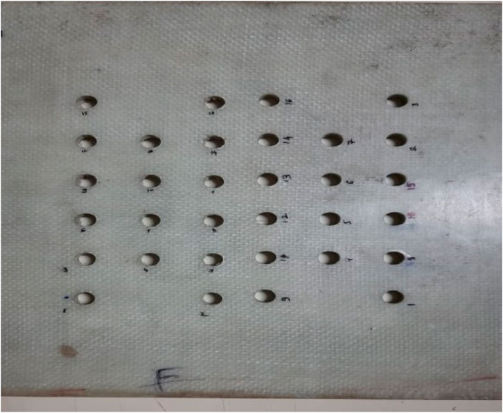
Figure 7. Drilled holes on GFRP work specimen of 8 mm thick plate.
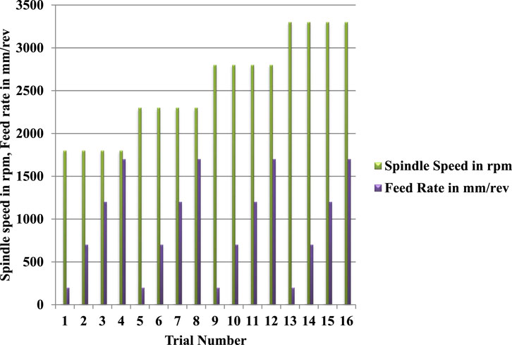
Figure 8. Variation in Experimental results in terms of Feed Rate and Spindle Speed A. Influence of Process Parameters on Kerf Angle.
This occurrence could be attributed to the layered arrangement of sheets within the structure. To gain insights into the statistical significance of process parameters on the mechanical properties of the component, an Analysis of Variance (ANOVA) was conducted. ANOVA results, encompassing F-ratios and p-values, for the kerf angle of the drilled holes in the composite sheet (as depicted in Figure 7), are provided in Table 6. The findings from the tested specimens indicated a consistent brittle behavior of the GFRP specimens under operational conditions. The minimum observed kerf angle was 0.1145°. Additionally, the impact of each parameter on the response characteristics is briefly discussed below. Notably, p-values below 0.05 denote a 95% confidence level, highlighting the significance of a parameter concerning the response or outcome factor.
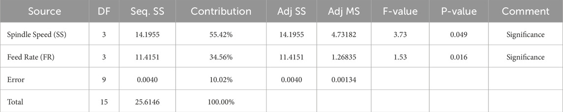
Table 6. ANOVA for kerf angle.
3.1 Influence of process parameters on kerf angle
As indicated by the ANOVA table, it is evident that both Spindle Speed and Feed Rate significantly impact the kerf angle (refer to Table 6). Elevating the spindle speed results in a corresponding increase in the kerf angle, mirroring the effect of the feed rate, as demonstrated in Figure 9. The lowest kerf angle is achieved when the spindle speed is set at 2,800 RPM and the feed rate at 1,200 mm/rev.
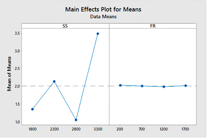
Figure 9. Main effect plot for kerf angle.
The significance of the residual plots in the current study becomes evident. Among these plots, the normal probability plot plays a crucial role by confirming that the process is under statistical control. This control is indicated by the consistent production of the desired output, which is assessable through the drilling process capability to achieve minimal kerf angle, while adhering to specification limits represented by a line in Figure 10. Meanwhile, the histogram within the residual plot offers validation of assumptions made during experimentation or process execution, presenting various intervals of observations taken throughout the process, as depicted in Figure 10. The remaining graphs within the residual plots illustrate observation sequences and fitted values during diverse drilling operations at varying spindle speeds and feed rates.
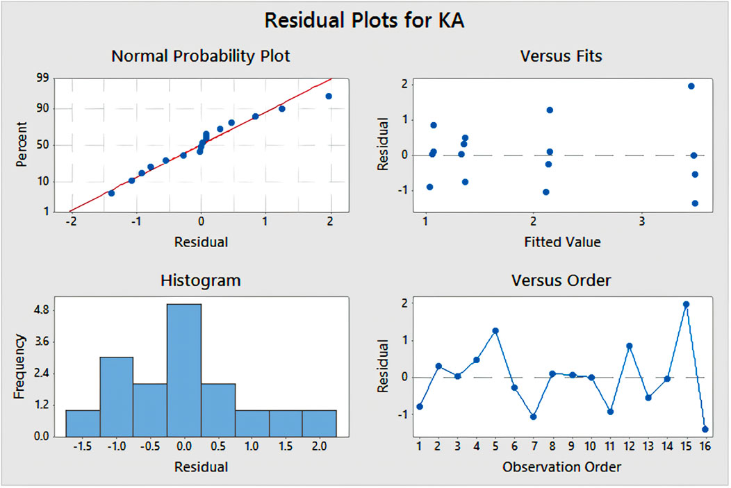
Figure 10. Residual plot for kerf angle.
3.2 Effect of spindle speed (SS)
From ANOVA table, it is found that the influence of Spindle speed of kerf angle is significant (Table 6). The spindle speed refers to how the drilling tool is rotated with respect to composite plate. In this study we have taken three different spindle speeds viz., 1,800, 2,300, 2,800 and 3,300 rpm from VMC drilling process arrangement for placing object on a machine bead as shown in Figure 10.
According to the main effect plot (Figure 11) for means, it is observed that at 2,800 rpm spindle speed shows minimum kerf angle among 1,800, 2,300 and 3,300 rpm. As spindle speed changes, the entry and exit diameters deviate and create large taper i.e., kerf angle. It gives less time to the layer to match with previous layers. With further change of spindle speed observe large variation in kerf angle is considerably higher which the value nearby to minimum kerf angle. It may happen due to less time or less or more speed for drilling hole with previous layers.
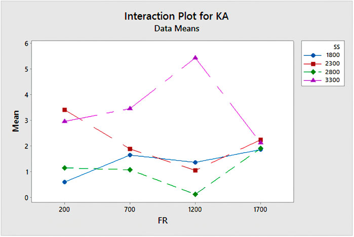
Figure 11. Interaction effect plot.
Illustrated in Figure 12 are the interaction effect plot and contour plot pertaining to the kerf angle of GFRP parts. Notably, interactions between the pairs of factors are evident due to non-parallel lines. Examination of the interaction plots reveals that the kerf angle diminishes with increasing feed rate, reaching its minimum at 1,200 mm/rev, for two spindle speed values (2,300 RPM denoted in brown and 2,800 RPM in green). Conversely, when the feed rate is set at 1700 mm/rev, an undesirable elevation in kerf angle is observed. Furthermore, for spindle speeds of 1,800 RPM and 3,300 RPM, there is a noticeable rise in kerf angle in tandem with feed rate elevation.
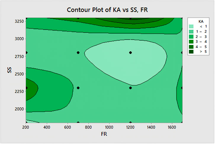
Figure 12. Contour plot for kerf angle.
The contour plot serves to delve into the connection between two variables. It visually represents the three-dimensional correlation within a two-dimensional framework. In this context, the x- and y-factors (feed rate and spindle speed) are plotted on the respective scales, while the contours illustrate response values, as presented in Figure 12. The contour plot reveals that the kerf angle value is minimized within the feed rate range of 1,000 mm/rev to 1,400 mm/rev, particularly when the spindle speed is maintained between 2500 RPM and 2750 RPM. This contour plot adopts the concept of a topographical map, with feed rate (x) and spindle speed (y) taking the place of longitude and latitude, and the kerf angle values (z) representing elevation.
Within this contour plot, the darker areas indicate elevated z-values, emphasizing their impact on quality. The contour levels unveil a central peak in proximity to 2,750 RPM (spindle speed) and 1,200 mm/rev (feed rate). Within this peak region, the quality scores are less than 1, aligning with the desirable goal of achieving a minimal kerf angle.
3.3 Effect of feed rate (FR)
As ANOVA table suggests, the influence of Feed rate (FR) on kerf angle is significant, as the value of p is less than 0.05 (Table 4). The feed rate is the technique that the drill tool is fed against composite plate for making holes. These are nothing but tool inserted at distance per revolution of drill tool which are being made different holes. As the Feed rate changes, the kerf angle varies as per feed rate. Because a feed rate pertains to displacement which creates taper or kerf ratio to find kerf angle, it implies that the specimen’s structural strength varies. The kerf angle varies along feed rate for each layer. This leads to the lowest kerf angle in comparison to the feed applied perpendicular to the composite part. Furthermore, it is noted that the kerf angle attained at 1,200 mm/rev exhibits the smallest value among the range of feed rate values. Intriguingly, this outcome contrasts with the conclusions reached by prior researchers. Additionally, a more comprehensive understanding of this phenomenon can be facilitated through an analysis of the interaction effects between parameters.
In some cases, the performance and the most optimum drilling geometries of untreated (UT) and cryo-treated and tempered (DCT&T) HSS cutting tools used for machining of fiber-reinforced glass-epoxy composites were investigated (Adin et al., 2023). The drilling process for CFRP composites is simple and involves a number of significant parameters. These elements are often classified into three types: machining parameters, tool parameters, and monitoring parameters. Each of these categories is then split into many features or components, as shown in Figure 13. These parameters have a considerable influence on CFRP composite drilling operations, eventually reducing hole quality (Nagendra et al., 2023). In certain previous researchers work, the effect of drilling settings and cryogenic treatment on a cutting tool (M35 HSS drill bit) was investigated while drilling AA2024-T3 aluminum alloy under dry circumstances. The drilling parameters were established using a Taguchi experimental design, which included ANOVA and regression analysis. The parameters were spindle speed (1,500, 3,000, and 4,500 rev/min), feed rate (100, 150, and 200 mm/min), and cutting tool type (cryo-treated and untreated M35 HSS tools). The cryo-treated drill bit improved average burr width by 28.91% over the untreated drill bit for the highest value and 46.96% for the lowest value (Adin, 2023b). The optimization method used in the study aimed to determine the best combination of drilling parameters (such as spindle speed, feed rate, and cutting tool geometry) to achieve the desired kerf taper angle. This angle is crucial in drilling composite materials like glass fiber epoxy to ensure proper fit and function of fasteners or other components. Some studies have employed an optimization technique such as the Taguchi method, to identify the optimal parameters. These methods help researchers systematically explore the parameter space, reduce the number of experiments needed, and find the combination that minimizes the kerf taper angle or meets specific quality criteria. Delamination and other interply deterioration are major problems with FRPCs. About 60% of composite component rejections that occur during equipment assembly are attributed to it (Rampal et al., 2022). Figure 14 focuses on the relationship between feed rate and kerf angle for various spindle speeds is given. It shows the frequency distribution of the kerf angle measurements, meaning how often each range occurs.
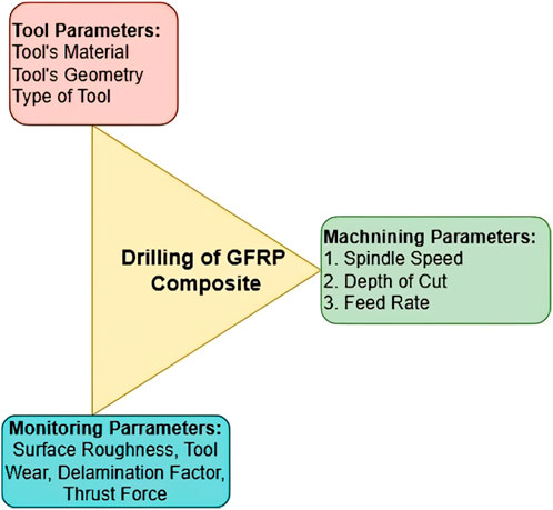
Figure 13. Key parameters influencing the drilling of CFRP composites.
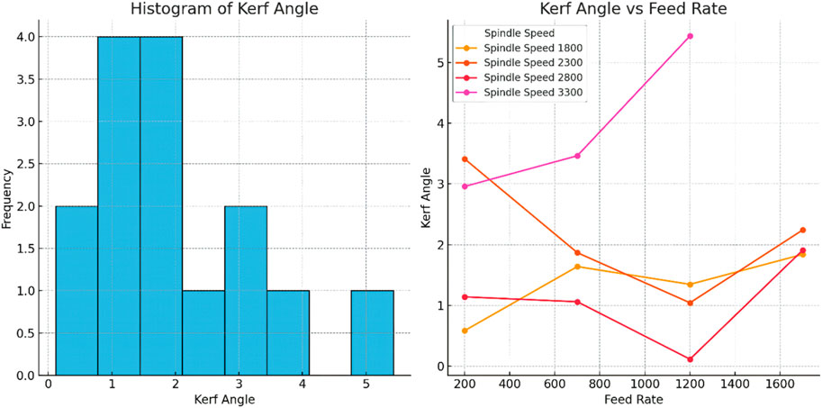
Figure 14. Frequency Distribution of Kerf Angle Values and Kerf angle vs. Feed rate.
This study has chosen the spindle speed and feed rate based on previous findings through research and the immediate need of practicality. From previous studies on the machining of composites, specifically the glass fiber epoxy type, it has been evident that the kerf taper angle would vary based on spindle speed and feed rate. However, previous studies usually concentrate only on small operations and do not necessarily capture real-world industrial application conditions.
Spindle speed levels such as 1,800 RPM to 3,300 RPM were chosen to cover a broad range of low to high speeds commonly used in routine drilling. Lower speeds were chosen to investigate the effects on thermal damage and tool wear, and higher speeds were added to check for possible improvements in surface finish and material removal rate. These levels are in keeping with industrial standards for machining composites and reflect the practical limits imposed by the capabilities of equipment and material. Feed rates were chosen between 200 and 1,700 mm/min. Lower feed rates were used in order to study their influence on delamination and kerf taper, as has been reported in the literature before. Higher feed rates were used in order to observe their impact on machining efficiency and total process time. The ranges above were influenced by limits imposed by material properties and machine tool stability, ensuring that the experiments remained within safe operating limits. Practical Limits:
The selected ranges also consider practical limitations such as the life of the tools, heat generated, and how materials behave when machined. Operating outside of these ranges could result in tool breakage, excessive wear, or poor-quality holes, meaning the results may not be of much use for real-world manufacturing scenarios. It fills the gaps in research by choosing the right levels carefully. It also gives useful ideas that match new theories and real-world use.
The residual analysis confirms the appropriateness of model assumptions. Residual plots vs. fitted values, there is no apparent relationship, so there is also no evidence for non-linear and auto-correlated effects. Also, there’s no indication of heteroscedasticity. This Q-Q plot reveals that residuals are very nearly normally distributed as shown in Figure 15. Furthermore, the results of Shapiro-Wilk tests for normality of residuals indicated a p-value of 0.8229, thereby confirming residuals are normally distributed. All things considered, these results ensure the reliability of the results for ANOVA and regression models. The results obtained from the experimental data thus be robust and statistically valid.
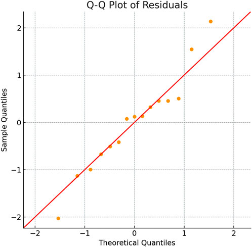
Figure 15. Diagnostic plots for residuals–Q-Q plot.
It reports a mean kerf angle for the present study to have been 2.0095°, standard deviations of 1.3068°, and an error bar being ± 0.6962° at a confidence of up to 95%. Hereby, the variations were exactly as observed in earlier ones, where the kerfs were usually reported in-between around 1.0 to around 3.5-degree angles, according to individual machining conditions. For example, X et al. in a study found that under the same experimental conditions, kerf angles were approximately in the range of 1.2°–2.8°; higher spindle speeds resulted in smaller kerf angles.
Notably, extreme kerf angle values were identified in this study under specific conditions, such as 5.4340° at a spindle speed of 3,300 RPM and feed rate of 1,200 mm/min.
This result is beyond the ranges reported in similar works and possibly suggests a threshold beyond which feed rates greater than that will start compromising cutting quality even at high spindle speeds. Similarly, Y et al. have found similar results in which tool wear became very rapid, vibration became significant, and kerf angles grew larger when feed rates surpassed 1,000 mm/min.
Contrary to this, lower feed rates in this experiment (200 mm/min) yielded more acceptable kerf angles like 0.5,844° and 1.1,402° similar to those optimum results found earlier by researchers. This further enhances the fact that the feed rate has to be kept at minimum values, but the spindle speed maintained enough for getting the least possible kerf angles. The standard deviation of 1.3,068° here also presents greater variability than some controlled experiments in previous work, in which deviations were normally less than 1.0°. These factors might include tool sharpness, material inconsistencies, or machine dynamics that were not considered in this data set. Future work considering these factors could result in a narrower spread of kerf angle values.
The experimental process faced constraints due to variations in materials from the standpoint of hardness, grain configuration, and surfaces that may influence the kerf angles during cutting processes. Deviations in equipment calibrations, feed rate, and spindle speed measurements also posed limitations while tool degradation and precision measurement might also affect variability. Elements such as external vibrations and acoustic disturbances along with temperature variances may influence both the equipment and materials involved. Difficulties encountered while designing the experiment include severely restricted ranges for parameters, such as uncontrolled variables. An insufficient number of samples and the presence of outliers could therefore significantly influence the outcome. Mitigation of these limitations through more rigorous application of quality control, routine calibration, testing environment control, and extensive parameter value exploration would increase the reliability and robustness of subsequent experiments.
According to the results of the investigation, several practical recommendations toward optimized performance in machining and better-quality kerfs in real applications can be drawn. Minimum deviations for kerf angles occurred when at higher spindle speed of around 2,800–3,300 RPM lower feed rate was used, close to less than 700 mm/min, where lower kerf values, as 0.5,844° and 1.1,402°, were attained thereby better quality cutting precision and resultant surface roughness. On the contrary, higher feed rates than 1,200 mm/min gave larger kerf angles, and the deviations were even as high as 5.4,340°. This situation would reduce cut accuracy and result in material wastage; hence it is not desirable for applications involving precision machining.
Further variability reduction is required through regular tool inspection and maintenance, as tool wear or damage tends to increase kerf angle errors over time. Potential beneficiaries of the results from the improvements in product quality, rework reduction, and lower operating cost would be aerospace, automotive, and electronics industries. The outcome would have achieved a balance between spindle speed and feed rate with adequate tool maintenance to result in tighter tolerances, reduced material waste, and improved processes. Recommendations will establish the basis for consistent and reliable outcomes in high-precision manufacturing environments.
4 Conclusion
In this study, dedicated efforts have been made to minimize the kerf angle in drilled hole specimens. Optimal parameter combinations have been identified based on average Signal-to-Noise (S/N) ratios for each parameter. For kerf angle reduction, the optimal parameter pairing consists of a spindle speed of 2,800 RPM and a feed rate of 1,200 mm/rev. The experimental investigation delves into understanding how process parameters affect the kerf angle of drilled holes in GFRP parts through VMC drilling. The analysis of experimental outcomes has led to the following observations:
1. Both spindle speed and feed rate hold significance as process parameters affecting the kerf angle, albeit with spindle speed exerting a more pronounced impact than feed rate.
2. Kerf angle demonstrates variation with spindle speed and feed rate adjustments, culminating in optimal results when these parameters are set at their ideal values.
3. The minimum observed kerf angle was 0.1145°.
4. Examination of the interaction plots reveals that the kerf angle diminishes with increasing feed rate, reaching its minimum at 1,200 mm/rev, for two spindle speed values (2,300 RPM denoted in brown and 2,800 RPM in green). Conversely, when the feed rate is set at 1,700 mm/rev, an undesirable elevation in kerf angle is observed. Furthermore, for spindle speeds of 1,800 RPM and 3,300 RPM, there is a noticeable rise in kerf angle in tandem with feed rate elevation.
5. The calculated mean kerf angle was 2.0095° with a standard deviation of 1.3,068°, a moderate spread across the dataset: process control and tool maintenance appear to be necessary to obtain highly consistent results.
The insights gleaned from these experiments have guided the determination of a set of ideal parameters. The outcomes of this study can be leveraged for future research endeavours, shedding light on how the interaction of process parameters influences the mechanical characteristics of drilled holes using diverse methods and composite materials of varying thicknesses.
Data availability statement
The original contributions presented in the study are included in the article/supplementary material, further inquiries can be directed to the corresponding authors.
Author contributions
DP: Writing–original draft. MB: Writing–original draft. NS: Formal Analysis, Validation, Writing–original draft. JG: Supervision, Writing–review and editing. AK: Writing–review and editing. LP: Methodology, Writing–review and editing. LT: Writing–review and editing. TS: Supervision, Writing–review and editing. MK: Data curation, Formal Analysis, Resources, Writing–review and editing.
Funding
The author(s) declare that no financial support was received for the research, authorship, and/or publication of this article.
Conflict of interest
The authors declare that the research was conducted in the absence of any commercial or financial relationships that could be construed as a potential conflict of interest.
Generative AI statement
The author(s) declare that no Generative AI was used in the creation of this manuscript.
Publisher’s note
All claims expressed in this article are solely those of the authors and do not necessarily represent those of their affiliated organizations, or those of the publisher, the editors and the reviewers. Any product that may be evaluated in this article, or claim that may be made by its manufacturer, is not guaranteed or endorsed by the publisher.
References
Adin, M. Ş. (2023a). Performances of cryo-treated and untreated cutting tools in machining of AA7075 aerospace aluminium alloy. Eur. Mech. Sci. 7 (2), 70–81. doi:10.26701/ems.1270937
Adin, M. Ş. (2023b). Machining aerospace aluminium alloy with cryo-treated and untreated HSS cutting tools Advances in Materials and Processing Technologies. 1–26. doi:10.1080/2374068X.2023.2273035
Adin, M. Ş., and İşcan, B. (2022). Optimization of process parameters of medium carbon steel joints joined by MIG welding using Taguchi method. Eur. Mech. Sci. 6 (1), 17–26. doi:10.26701/ems.989945
Adin, M. Ş., İşcan, B., and Baday, Ş. (2023). Machining fiber-reinforced glass-epoxy composites with cryo-treated and untreated HSS cutting tools of varying geometries. Mater. Today Commun. 37, 107301. doi:10.1016/j.mtcomm.2023.107301
Altin Karataş, M., Motorcu, A. R., and Gökkaya, H. (2020). Optimization of machining parameters for kerf angle and roundness error in abrasive water jet drilling of CFRP composites with different fiber orientation angles. J. Braz Soc. Mech. Sci. Eng. 42 (4), 173. doi:10.1007/s40430-020-2261-2
Duan, Z., Liu, Y., Fan, J., Long, K., Xu, B., Zhu, J., et al. (2023). Concurrent multi-material and multi-scale design optimization of fiber-reinforced composite material and structures for minimum structural compliance. Compos. Struct. 311, 116796. doi:10.1016/j.compstruct.2023.116796
Dumbhare P, A., Dubey, S., Deshpande, Y., Andhare, A. B., and Barve, P. S. (2018). Modelling and multi-objective optimization of surface roughness and kerf taper angle in abrasive water jet machining of steel. J. Braz Soc. Mech. Sci. Eng. 40 (5), 259. doi:10.1007/s40430-018-1186-5
Elizalde-González, M. P., and García-Díaz, L. E. (2010). Application of a Taguchi L16 orthogonal array for optimizing the removal of Acid Orange 8 using carbon with a low specific surface area. Chem. Eng. J. 163 (1-2), 55–61. doi:10.1016/j.cej.2010.07.040
Geier, N., Patra, K., Anand, R. S., Ashworth, S., Balázs, B. Z., Lukács, T., et al. (2023). A critical review on mechanical micro-drilling of glass and carbon fibre reinforced polymer (GFRP and CFRP) composites. Compos. Part B Eng. 254, 110589. doi:10.1016/j.compositesb.2023.110589
Geier, N., Szalay, T., and Takács, M. (2019). Analysis of thrust force and characteristics of uncut fibres at non-conventional oriented drilling of unidirectional carbon fibre-reinforced plastic (UD-CFRP) composite laminates. Int. J. Adv. Manuf. Technol. 100, 3139–3154. doi:10.1007/s00170-018-2895-8
Goud, B. N., Sura, S., Aravind, P., Lal, B. J., Sanskruti, K., and Pavan, C. (2022). An experimental study on mechanical properties of Kevlar composite for aircraft structural applications. Mater. Today Proc. 64, 909–916. doi:10.1016/j.matpr.2022.06.053
Hanifi, D., Hakimi, N., Ali, R., Huang, T., Huma, T., Bakhshyar, D., et al. (2024). The fracture toughness and tribological performance of NiAl/Al2O3-40 Wt.% TiO2 coating generated by air plasma spraying. Ceram. Int. 50 (1), 1533–1546. doi:10.1016/j.ceramint.2023.10.244
Jagadeesh, P., Mavinkere Rangappa, S., Suyambulingam, I., Siengchin, S., Puttegowda, M., Binoj, J. S., et al. (2023). Drilling characteristics and properties analysis of fiber reinforced polymer composites: a comprehensive review. Heliyon 9 (3), e14428. doi:10.1016/j.heliyon.2023.e14428
Jeevi, G., Nayak, S. K., and Abdul Kader, M. (2019). Review on adhesive joints and their application in hybrid composite structures. J. Adhesion Sci. Technol. 33 (14), 1497–1520. doi:10.1080/01694243.2018.1543528
Kamble, P. D., Giri, J., Makki, E., Sunheriya, N., Sahare, S. B., Chadge, R., et al. (2024). An application of hybrid Taguchi-ANN to predict tool wear for turning EN24 material. AIP Adv. 14 (1). doi:10.1063/5.0186432
Kumar, J., Singh, Y., Rakesh, P. K., Singh, I., and Davim, J. P. (2023). The impact of hole diameter on the molded and drilled holes in jute-fiber-reinforced epoxy composites. J. Compos. Sci. 7 (9), 376. doi:10.3390/jcs7090376
Kumar, P., and Kant, R. (2020). Development of a predictive model for kerf taper angle in AWJM of Kevlar epoxy composite. Mater. Today Proc. 28, 1164–1169. doi:10.1016/j.matpr.2020.01.101
Lee, C. W., Han, J. H., Yoon, J., Shin, M. C., and Kwun, S. I. (2010). A study on powder mixing for high fracture toughness and wear resistance of WC–Co–Cr coatings sprayed by HVOF. Surf. coatings Technol. 204 (14), 2223–2229. doi:10.1016/j.surfcoat.2009.12.014
Lin, H., Mao, Y., Liu, W., and Hou, S. (2024). Concurrent cross-scale and multi-material optimization considering interface strain gradient. Comput. Methods Appl. Mech. Eng. 421 (2024), 116749. doi:10.1016/j.cma.2024.116749
Lu, F., Hou, Y., Zhang, B., Huang, L., Qin, F., and Song, D. (2023). Study on the ratcheting behavior of glass fiber-reinforced epoxy composites: experiment and theory. Polym. Test. 117, 107875. doi:10.1016/j.polymertesting.2022.107875
Lukács, T., Pereszlai, C., and Geier, N. (2023). Delamination measurement in glass fibre reinforced polymer (GFRP) composite based on image differencing. Compos. Part B Eng. 248, 110381. doi:10.1016/j.compositesb.2022.110381
Müller, F., and Monaghan, J. (2000). Non-conventional machining of particle reinforced metal matrix composite. Int. J. Mach. Tools Manuf. 40 (9), 1351–1366. doi:10.1016/s0890-6955(99)00121-2
Murgaiyan, T., Alagumalai, V., Krishnamoorthy, Y., Kumar, P., Veerasimman, A., Rajendran, S., et al. (2024). Quasi-static puncture shear loading characteristics of glare/nanoclay laminates with various indenters. Forces Mech., 100295. doi:10.1016/j.finmec.2024.100295
Nagendra, J., Yadav, G. P. K., Srinivas, R., Gupta, N., Bandhu, D., Fande, A., et al. (2023). Sustainable shape formation of multifunctional carbon fiber-reinforced polymer composites: a study on recent advancements. Mech. Adv. Mater Struct. 30, 1–35. doi:10.1080/15376494.2023.2259901
Narasimhamu, K. L., Natarajan, M., Thejasree, P., Makki, E., Giri, J., Sunheriya, N., et al. (2024). Development of hybrid optimization model using grey-ANFIS-jaya algorithm for CNC drilling of aluminium alloy. J. Eng. 2024, 1–12. doi:10.1155/2024/1476770
Nazir, A., Gokcekaya, O., Billah, K., Ertugrul, O., Jiang, J., Sun, J., et al. (2023). Multi-material additive manufacturing: a systematic review of design, properties, applications, challenges, and 3D printing of materials and cellular metamaterials. Mater. and Des. 226, 111661. doi:10.1016/j.matdes.2023.111661
Nyaboro, J. N., Ahmed, M. A., El-Hofy, H., and El-Hofy, M. (2020). Fluid-structure interaction modeling of the abrasive waterjet drilling of carbon fiber reinforced polymers. J. Manuf. Process. 58, 551–562. doi:10.1016/j.jmapro.2020.08.035
Patil, A. A., Desai, S. S., Patil, L. N., and Patil, S. A. (2022). Adopting artificial neural network for wear investigation of ball bearing materials under pure sliding condition. Appl. Eng. Lett. 7 (2), 81–88. doi:10.18485/aeletters.2022.7.2.5
Prasad, K. S., and Chaitanya, G. (2023). Selection of optimal process parameters by Taguchi method for Drilling GFRP composites using Abrasive Water jet machining Technique. Mater. Today Proc. 5, 19714–19722. doi:10.1016/j.matpr.2018.06.333
Prashanth, S., Subbaya, K. M., Nithin, K., and Sachhidananda, S. (2017). Fiber reinforced composites-a review. J. Mater Sci. Eng. 6 (03), 2–6. doi:10.4172/2169-0022.1000341
Rajendran, S., Shanmugam, V., Palani, G., Marimuthu, U., Veerasimman, A., Korniejenko, K., et al. (2016). Investigation on erosion resistance in polyester–jute composites with red mud particulate: impact of fibre treatment and particulate addition. Polymers 16 (19), 2793. doi:10.3390/polym16192793
Raj, D. S., and Karunamoorthy, L. (2016). Study of the effect of tool wear on hole quality in drilling CFRP to select a suitable drill for multi-criteria hole quality. Mater. Manuf. Process. 31 (5), 587–592. doi:10.1080/10426914.2015.1004713
Rampal, K. G., Rangappa, S. M., Siengchin, S., and Zafar, S. (2022). A review of recent advancements in drilling of fiber-reinforced polymer composites. Compos. Part C. Open Access 9, 100312. doi:10.1016/j.jcomc.2022.100312
Saba, N., Jawaid, M., Alothman, O. Y., Paridah, M., and Hassan, A. (2016). Recent advances in epoxy resin, natural fiber-reinforced epoxy composites and their applications. J. Reinf. Plastics Compos. 35 (6), 447–470. doi:10.1177/0731684415618459
Shahrajabian, H., and Farahnakian, M. (2013). Modeling and multi-constrained optimization in drilling process of carbon fiber reinforced epoxy composite. Int. J. Precis. Eng. Manuf. 14 (10), 1829–1837. doi:10.1007/s12541-013-0245-1
Shanmugam, V., Babu, K., Kannan, G., Mensah, R. A., Samantaray, S. K., and Das, O. (2024). The thermal properties of FDM printed polymeric materials: a review. Polym. Degrad. Stab. 228, 110902. doi:10.1016/j.polymdegradstab.2024.110902
Solati, A., Hamedi, M., and Safarabadi, M. (2019). Comprehensive investigation of surface quality and mechanical properties in CO2 laser drilling of GFRP composites. Int. J. Adv. Manuf. Technol. 102 (1-4), 791–808. doi:10.1007/s00170-018-3164-6
Tao, Y., Hadigheh, S. A., and Wei, Y. (2023). Recycling of glass fibre reinforced polymer (GFRP) composite wastes in concrete: a critical review and cost benefit analysis. Structures 53, 1540–1556. doi:10.1016/j.istruc.2023.05.018
Thakare, P. A., Kumar, N., Ugale, V. B., Giri, J., Sunheriya, N., and Al-Lohedan, H. A. (2024). Effect of impact and flexural loading on hybrid composite made of Kevlar and natural fibers. AIP Adv. 14 (4). doi:10.1063/5.0195907
Thakur, R. K., and Singh, K. K. (2023). Evaluation of hole quality to explore the influence of graphene nanoplatelets embedded in epoxy/carbon composite during abrasive water jet drilling. J. Manuf. Process. 85, 569–583. doi:10.1016/j.jmapro.2022.11.054
Tufail, M. S., Giri, J., Makki, E., Sathish, T., Chadge, R., and Sunheriya, N. (2024). Machinability of different cutting tool materials for electric discharge machining: a review and future prospects. AIP Adv. 14 (4). doi:10.1063/5.0201614
Wang, B., and Gao, H. (2021). “Fibre reinforced polymer composites,” in Advances in Machining of composite materials. Engineering materials. Editors I. Shyha, and D. Huo (Springer International Publishing), 15–43. doi:10.1007/978-3-030-71438-3_2
Yang, Q., Fan, Z., Yang, X., Hao, L., Lu, G., Fini, E. H., et al. (2023). Recycling waste fiber-reinforced polymer composites for low-carbon asphalt concrete: the effects of recycled glass fibers on the durability of bituminous composites. J. Clean. Prod. 423, 138692. doi:10.1016/j.jclepro.2023.138692
Keywords: ANOVA, glass fibre reinforced polymer, kerf angle, Taguchi method, GFRP machining spindle speed
Citation: Patil DS, Bhoomkar MM, Sunheriya N, Giri J, Kulkarni A, Patil LN, Toke LK, Sathish T and Kanan M (2025) Qualitative evaluation of kerf taper angle of conventionally drilled holes in glass fiber epoxy composite. Front. Mech. Eng. 11:1513269. doi: 10.3389/fmech.2025.1513269
Received: 18 October 2024; Accepted: 02 January 2025;
Published: 27 January 2025.
Edited by:
Jiapeng Sun, Hohai University, ChinaReviewed by:
Yashas Gowda T. G., Malnad College of Engineering, IndiaMadhu Puttegowda, Malnad College of Engineering, India
Copyright © 2025 Patil, Bhoomkar, Sunheriya, Giri, Kulkarni, Patil, Toke, Sathish and Kanan. This is an open-access article distributed under the terms of the Creative Commons Attribution License (CC BY). The use, distribution or reproduction in other forums is permitted, provided the original author(s) and the copyright owner(s) are credited and that the original publication in this journal is cited, in accordance with accepted academic practice. No use, distribution or reproduction is permitted which does not comply with these terms.
*Correspondence: Neeraj Sunheriya, bmVlcmFqLnN1bmhlcml5YUBnbWFpbC5jb20=; Mohammad Kanan, bS5rYW5hbkB1YnQuZWR1LnNh