- 1Division of Fluid and Mechatronic Systems, Linköping University, Linköping, Sweden
- 2Hiab AB, Hudiksvall, Sweden
This work presents a process for the requirement management and conceptual design phases of hydraulic systems. The aim is to provide a foundation for developing more energy efficient systems for the working hydraulics of construction machines. A framework is developed and applied in a case study of a loader crane. An important part of the framework is to evaluate and compare different designs based on customer usage of the machine. Emphasis has also been put on incorporating the knowledge and experience of both industry and academia. A large number of different designs are evaluated during a concept exploration phase. The design space is then narrowed down to the system design analysis phase. Losses from simultaneous operation are significant, systems with two and four pumps respectively are therefore selected for analysis by demonstrators. In order to reach equal energy performance, two-pump systems need to be more complex, i.e., they require a more sophisticated control and more components, than four-pump systems. When comparing demonstrator results, the conclusion is that for two-pump systems, it is more challenging to reach the theoretical performance, both in terms of energy efficiency and of drivability, than for the less complex systems made possible with four-pumps.
1 Introduction
The paper presents a framework of how different designs of the hydraulic system of a mobile application, can be generated, compared and evaluated based on customer needs, high-level models and prototype studies. The main driver for investigating new systems is to reduce the energy consumption, but in order to also include other properties of importance to the customers and end-users, the target is to be able to use the framework for selecting the most “suitable” system rather than the most “energy efficient” system. Suitable here refers to that the system should be well adapted to customer needs such as drivability, energy performance, cost of investment, physical dimensions etc.
All systems under consideration in this work have in common that they exploit the properties of an electric drive system. Electric drives provide new control possibilities, such as speed control down to 0 rpm, possibilities of regenerating and using several systems in parallel, but also put a high demand on energy efficiency of the complete system, due to the high cost and low energy density of batteries. The paper is focused on the requirement management and conceptual design phases of a system level design and is applied in a case study of a loader crane. As part of that work, a new system design with a dual pump approach with open flow control is developed and evaluated on a demonstrator. Systems with pump controlled cylinders have been developed and tested by other studies within the same research project and will also be part of the analysis phase of the framework.
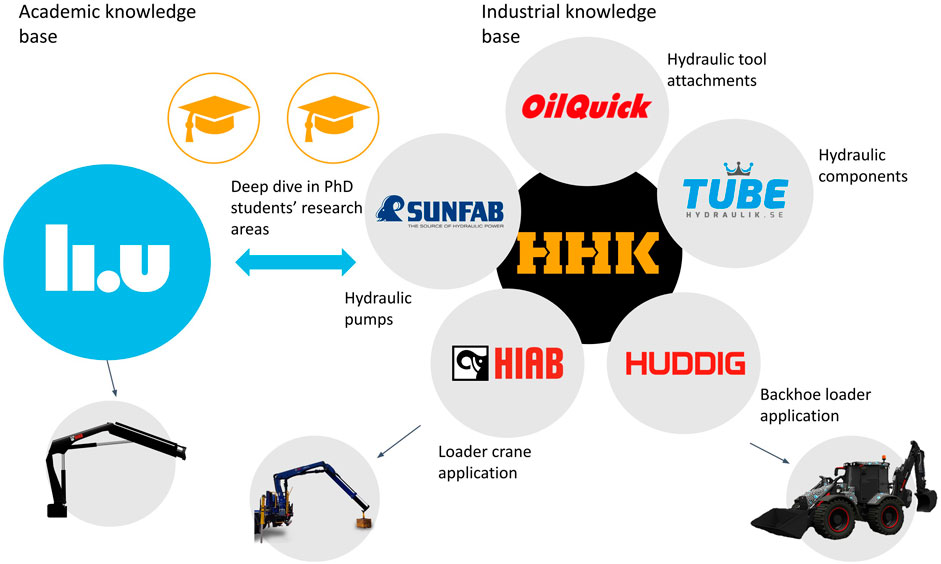
The work presented in this paper has been part of a research project called Stealth, which is a collaboration between Linköping University and a number of companies within the Hudiksvall Hydraulic Cluster according to Figure 1. The project benefits from that ideas can be found by combining the experience and knowledge of the different project members, and that experiments can be carried out on different applications and at different entities. The overall research question of Stealth is How can a load handling system for a truck be optimized for an electric drive in order to minimize energy consumption, noise and cost of the complete drive cycle? The methodology of this work is based on the assumption that, in order to find an answer to the question, it is more efficient to investigate a large number of new concepts on a rather high level before selecting a few for a more in-depth analysis that includes building demonstrators, than selecting a single new concept directly. By doing so, the expectation is to avoid the design paradox that important design decisions often have to be made before enough information about the system is known. Another important aspect is to make sure that all results are as relevant to the intended application as possible and that design choices and optimizations are done based on the actual usage of the machine.
2 Literature review
There are a lot of studies that presents and investigate hydraulic systems that promise to be more energy efficient than the conventional system. With speed controlled electric motors, the system flow rather than the system pressure can be controlled which can reduce the energy consumption at low and medium speed operation. This has been studied, for example, in the context of an excavator (Finzel et al., 2010), and of a wheel loader (Axin et al., 2009). In the latter, open flow control, where the flow to the heaviest load is controlled directly from the pump, is successfully implemented in addition to the basic flow control where the pump is flow controlled but all actuators are valve controlled. When used on the wheel loader performing a short loading cycle, the reduction is found to be 14%. In another study, a variant of open flow control, denoted electronic flow matching, is applied to an excavator (Bedotti et al., 2018). The energy savings are in simulations 18% for a trench digging cycle and 47% for a levelling cycle. When flow control is compared to load sensing for a forestry crane application, the energy consumption is reduced between 8% and 15% for different types of flow control and open flow control strategies (Scherer et al., 2013).
For a system driven by an electric motor that will be switched on and off regularly, the dynamics and energy efficiency during start-up could become relevant. One way of dealing with this is to adjust the control of the proportional valve of the cylinder that is to be activated, similarly to what is done for a hydrostatic transmission in Bury et al. (2022).
A concept that becomes highly interesting when using electric drives is to use multiple pump-motor units to supply the hydraulic system. Using one supply unit for each actuator removes the losses otherwise induced by different pressure levels in different actuators. An electro-hydraulic cylinder on a stiff boom crane is studied in two connected papers, Hagen et al. (2019a) and Hagen et al. (2019b). The motion control is found to be better both in terms of position tracking and response than the valved controlled reference. The energy reduction for the electro-hydraulic cylinder is found to be 37% on the test cycle where 20% of the consumed energy was possible to recuperate. For asymmetric cylinders, such as the boom cylinders of a loader crane, a closed electro-hydraulic circuit needs a mechanism for handling the asymmetric flow. Different solutions are compared in a test rig, and with the proposed solution of using limited throttling valves for controlling the flow to the low pressure charge system in order to compensate for the asymmetric flow, the energy consumption of a specified motion is 23% of that of a load sensing system (Imam et al., 2018).
A good example of a system with more than one pump-motor but less than the number of actuators is a two-pump system for four actuators where the two pump circuits can be connected which is applied to an excavator (Finzel et al., 2010). At moderate flow demands, each pump is dedicated to two actuators, but when one of the circuits it demanding more flow than it can deliver, the two circuits are connected. The system is found, in simulations, to reduce the energy consumption of an excavator work cycle with 30% compared to a load sensing system. The authors claim that the small errors in delivered flow during coupling situations would not be noticeable to an operator.
In a recent study, two electric motor-pump units are used to power two high pressure rails to which all hydraulic actuators are connected to by independent metering valves, along their connection to a low pressure line (Opgenoorth et al., 2022). The system is an adapted version of the STEAM system (Vukovic and Leifeld, 2016).
An alternative to using multiple pump-motor units is to use hydraulic transformers connected to the main pump shaft. This has been tested, for example, in a study where the tilt and lift cylinders of a wheel loader are connected to one transformer each while the rest of the hydraulic system is kept in a load sensing circuit driven by a third transformer (Heybroek, 2017). A 9% fuel reduction per loaded mass during the short loading cycle was recorded during demonstrator testing. Instead of transformers, multi-chamber cylinders can be used to equalize pressure levels. A system with such cylinders connected to a high and a low pressure rail with accumulators together with rotational hydraulic actuators is implemented in an excavator demonstrator, and a fuel efficiency improvement of 34%–50% for the demonstrator system with regards to the baseline system with conventional cylinders and a main control valve was measured on a digging and dumping cycle (Heybroek and Sahlman, 2018). Having an accumulator connected to the pressure rail can take the power peaks of the system and thus enable downsizing of the drive components, but it is important to consider that the accumulator can lead to an increase in transient time (Stosiak and Karpenko, 2024).
Losses due to different pressure levels can also be reduced by making use of accumulators to create a system with multiple pressure rails. In the study with the adapted version of the STEAM system (Opgenoorth et al., 2022), the switching procedures of an electrically driven system for an excavator with independent metering controlled cylinders connected to two high and one low pressure rail are improved, resulting in an improvement in energy efficiency of 28.3% compared to a conventional single pump system on a dig and dump cycle.
Another approach to minimize losses from different pressure levels is to equalize the pressure levels. This can be done by opening up regenerative circuits on low-pressure cylinders which is enabled by independent metering systems that are commonly studies in literature (Eriksson, 2010; Shenouda, 2006). The pressure levels can also be equalized by increasing the backpressure on low pressure cylinders and storing the pressurized flow in an accumulator (Siebert et al., 2017). Independent metering systems can also enable energy efficient lowering motions and be used together with flow control (Wydra et al., 2017).
All these ideas seem promising but the prior studies does not say anything about how well suited they are for the application of this study. In order to find the most suitable system for the loader crane case study in question in a systematic way, incorporating prior knowledge, a framework is developed and followed.
A procedure that starts with application usage and demands and includes considerations about energy efficiency as well as practical issues and economics is proposed in a study, but not used for selecting the system investigated in the paper (Finzel et al., 2010). Work concerning the design process of hydraulic components can be found in the literature, see, for example, Pedersen et al. (2023), Salutagi et al. (2016) and Karpenko et al. (2023) where CFD and FE analyses are used to optimize and investigate hydraulic machines, valves and fittings respectively. These methods can be considered at a later stage when a new system design is being considered for turning into a product, but for this paper, publications regarding the design process of a construction machine working hydraulic system are of greater relevance and these are scarce. Another recent article, (Opgenoorth and Schmitz, 2023), presents a methodology with an analysis tool for selecting the complete drive system for the propulsion and working hydraulic systems of an excavator. The analysis is focused on selecting suitable sizes of motors and pumps and only briefly mentions that three different hydraulic architectures are compared.
The procedure of this study has instead been inspired by work within the Engineering System Design field in general. A study applied to mechatronic systems (Malmquist et al., 2014), presents an approach to shorten the time of the early concept evaluation by using high-level models similar to what is the aim of this article. Another study on the design of mechatronic systems, (Mhenni et al., 2014), proposes to use a SysML-based methodology in two steps where the first step considers the system as a black-box while setting the requirements, and the second step is a white-box analysis of the architecture of the system. The usage of Systems Engineering is also common in the aerospace engineering field, one example is a study where a number of different Systems Engineering concepts are discussed in the context of how they can be used in the product development of Systems of Systems (SoS) (Staack et al., 2019). Another examples is a paper where a design methodology for the flight actuator system of a more electric aircraft is presented that can solve the large combinatorical problem of selecting the best configuration for each part of the actuator system (Jiao et al., 2019). There is also an educational book (Sadraey, 2013), describing how the principles of systems engineering can be applied to the design process of aircraft. The design of an aircraft has a much higher complexity than that of the hydraulic system of a crane, but some general concepts, such as the use of analysis modules at different fidelity levels (Moerland, 2013), are applicable also in the context of this study.
3 Framework
A framework for the requirement management and conceptual design phase of the system design process suitable for the design of energy efficient hydraulic systems of construction machines has been developed. The framework is presented in Figure 2. During the requirement management phase, benchmarking of the reference system is empathized in order to make the rest of the design phase as relevant as possible to the real life situation. The conceptual design phase should start by exploring a large design space and then gradually narrow it down and investigate some concepts more in detail. The different steps are described in the list below:
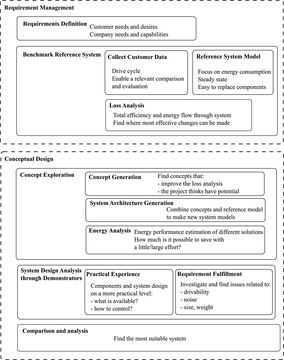
Figure 2. Framework for the requirement management and conceptual design phase of the system design process. The process starts with customer requirements and benchmarking, has a broad exploration phase and is wrapped up by an analysis of what could be the most suitable system.
4 Methods
The framework presented in the previous section is applied in a case study of a loader crane. The aim is to be able to find the most suitable electrified system for the intended application.
4.1 Reference application and system
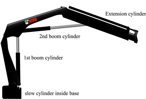
The reference application used in the case study is a medium sized loader crane used for brick and block handling. The crane has four hydraulic cylinders according to Figure 3. The hydraulic system of the crane, which, together with the drive system, is the system under consideration here, conventionally consists of a single pump and one of two valve architectures, open center or load sensing. In an open center system, a fixed flow is provided at a variable pump pressure. In a load sensing system, both the flow and the pressure is adapted to the current working point making it the most energy efficient of the two systems. Given that the load sensing system also has a higher controllability due to that the open center system suffers from load interference, it is the most suitable reference hydraulic system.
Most cranes on the market are still powered by the diesel engine of the truck but in order to be easily comparable with new systems, the reference system uses the currently more uncommon alternative of powering the pump with an electric motor. This system can vary the flow by using a fixed pump together with a speed controlled electric motor, as opposed to a diesel engine driven system that requires a variable displacement pump in order to vary the flow within the complete range of usage. The reference system together with the four cylinder of the crane is presented in Figure 4.
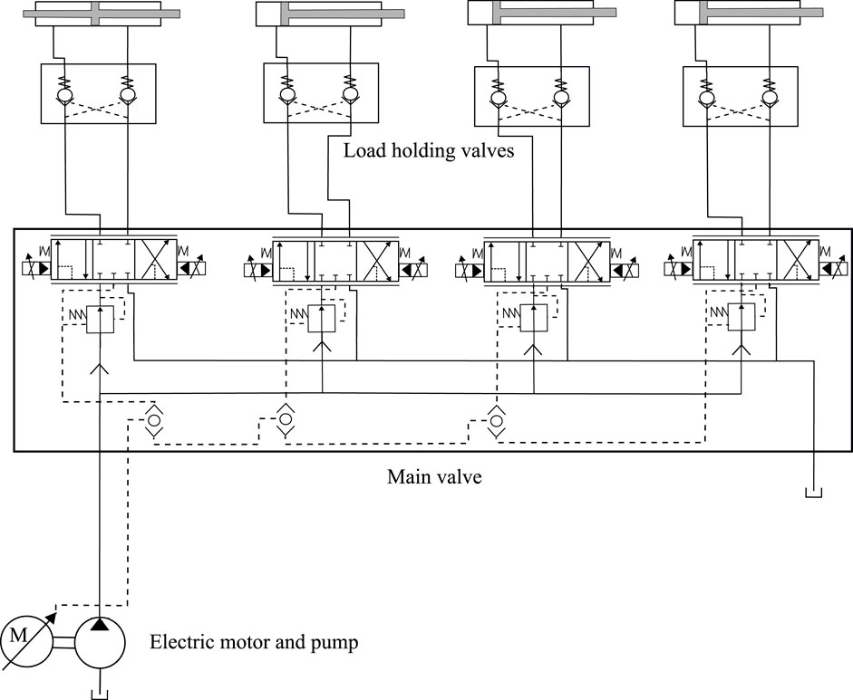
Figure 4. Reference load sensing system with an electric drive. The directional spools are pressure compensated and load holding valves are connected to each cylinder.
4.2 Requirements definition
The customer need in this case study is to be able to move a load from point A to point B. The load should be moved in a time- and cost efficient way. Legislation as well as the customer, and other stakeholders such as the customer’s customer, municipalities and people in the vicinity, might also have demands, needs and desires in terms of drivability, noise, environmental concern, safety and physical properties of the solution.
The solution that is considered in the case study is a loader crane powered by an electrically driven hydraulic system. The crane has a variable reach and possibility to attach a load. The hydraulic system allows the crane to lift the load and to move it around. To accomplish this task, the hydraulic system has three main functions: it supplies power, controls the system pressure and flow, and controls the actuator speeds. In addition, there is also a legal requirement of accounting for load holding and overload protection to ensure the safety of the operator and people and equipment in the vicinity of the crane. As no changes to the hydraulic cylinders will be considered in this study, the overload protection will not be affected, but the load holding needs to be handled by a fourth function.
To guarantee that new systems meet the customer needs, requirements related to the different functions are set up:
The investment cost of the reference system is high compared to a diesel driven system. For some customers, the higher cost is acceptable due to the sustainability label of zero local emissions and lower noise levels, but in order to stay competitive and attract a broader customer base, the cost must be lowered. It is difficult to make a fair estimation of the cost of new systems, the cost of the battery will depend on the available sizes, the selected technology as well as number of units ordered. Cost is therefore not set as an explicit target, only implicitly included in the energy reduction target.
Requirements on noise, weight and size of the system are not quantified, or mutually prioritized, since they are closely tied to the final industrial design. It is, however, considered throughout the process that they should all be as small as possible while fulfilling the other requirements. An important part of the concept exploration phase of the procedure is to gain experience, that can contribute to the overall system analysis, of how these properties are influenced by different concepts. Note that the absolute noise level of the electrified systems considered here is lower than for diesel driven systems, but without the noise from the diesel engine, the noise from the hydraulic components becomes much more distinct. The sounds and noise level will also vary more, which can be considered annoying for a human and should be taken into consideration.
Finally, it should be noted that there always are, in practice, requirements on the development process, manufacturing and maintenance set by the product owning company. These are also difficult to quantify, but a simplified view is that the development process should require little resources, make use of the experience and knowledge within the company, and result in a product that is technically possible to manufacture and maintain.
4.3 Benchmarking the reference system and application
In order to be able to make a fair comparison of different system solutions and to adapt them to the user demand, the reference application is benchmarked by customer data from field measurements. Data of operating points in terms of flow and pressure demand of the different cylinders is recorded during a 3 month period. The data can be used directly in static calculations and is also used to develop a drive cycle that can be used during evaluation of demonstrators. The details on how the drive cycle is developed can be found in Rankka et al. (2019).
The different components of the hydraulic system of the reference crane are investigated in a laboratory environment in order to create pressure drop models that form a model library of components used to develop a complete model of the reference system. The components of the drive system are modeled based on efficiency maps provided by the suppliers. At a later stage, the component models are easily replaced by models of new concepts. The reference model can, together with the operating points data from the field measurements, be used in a loss analysis of the reference system. The loss analysis is described in Rankka and Dell’Amico (2021), and provides information about where energy can be saved by making changes to the system design or control strategy. The losses are distributed according to Figure 5 and briefly described in the list below.
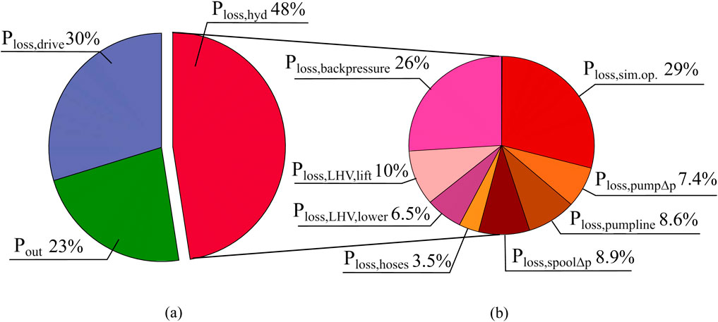
Figure 5. (A): Distribution of power on drive system losses, hydraulic system losses and output power. (B): Distribution of losses in hydraulic system.
4.4 Concept exploration
When the baseline for the system design has been set and the energy performance of the reference system has been visualized by the loss analysis, the conceptual design phase can be initialized.
In this phase, there is a close collaboration between the different project members. Concepts are generated during project workshops inspiring free thinking and creativity, and demonstrators are built on different applications and by different project members.
The concept exploration part is initialized by setting up a Function/Means tree, that originates from the requirement and functions of the hydraulic system of the reference application crane, and that can be drawn according to Figure 6. A number of means are displayed for each of the four functions. If the reference system is considered, one pump is used to supply power, a load sensing (LS) valve and pump controller controls the system pressure and flow, coupled metering (CM) spools control the actuator speeds and traditional hydraulic load holding valves (LHV) ensures load holding. According to the loss analysis, the solution for each of the these functions have the potential to be improved from an energy perspective while still fulfilling the other requirements. New concepts for all categories are generated within the project and put together to form new systems.
4.4.1 Concept generation within project
The project group consisted of several experts both from the industry and the academia with a large experience of hydraulic systems and construction machines. In order to include all that knowledge and experience while at the same time encouraging new ideas when generating concepts, workshops with an innovation methodology developed by the Hudiksvall Hydraulic Cluster to facilitate the collaboration between industrial companies of different size and the academia, were held within the project. The participation of industry ensured that only concepts that conform to the company needs and capabilities and have a reasonable possibility of being commercialized were included. A Quality Function Deployment matrix was set up to visualize the relationship between product and research demands and desires and the priorities of different requirements.
On a high level, the project decided to focus on five different loss reducing concepts, according to Table 1, as well as a few recuperation and regeneration concepts. Note that losses in hoses, tubes and couplings are not in the scope of this study, but should be considered in the industrial design given that their loss contribution is not insignificant and their properties, such as sizes, bends and type of couplings, have an impact on the pressure losses, which is analyzed, for example, in Karpenko et al. (2023).
Electric load holding valves (ELHV) is a load holding solution where only an electric signal is needed to open up the meter-out side during lowering motions and where the pressure drop over the restriction on the meter-in side is minimized. With flow control (FC), the system flow is controlled rather than the pressure (as is the case for load sensing systems). Open flow control (OFC) is both a means to control the system pressure and flow (by flow control) and a means to control the speed of one of the actuators (directly by the pump flow through a completely open directional spool). As an addition to the traditional coupled metering (CP) of the meter in and meter out spool, independent metering (IM) is considered. If combined with electric load holding valves (denoted IM1 in Table 2), independent metering can significantly lower the backpressure in the cylinders. Regeneration of energy from one function to another (denoted IM3), and regeneration of oil on an individual cylinder to equalize pressure levels (denoted IM2), is investigated as part of some independent metering systems. The selected concept for recuperation is to run the pump and electric motor backwards and recharging the battery.
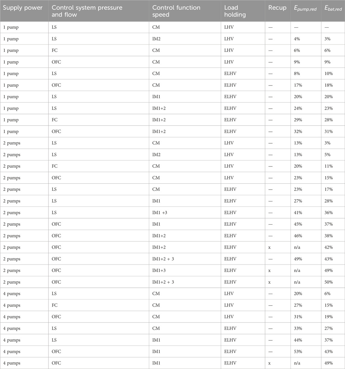
Table 2. Energy consumption reduction for the hydraulic system (energy from pump) and for the complete system (energy from battery) with regards to the reference system for different system setups.
4.4.2 System architecture generation and energy analysis
A large number of new conceptual systems architectures, ranging from systems very similar to the reference system to systems with completely different architectures, were created by combining different concepts according to the Function/Means tree in Figure 6.
In order to be able to compare the energy performance of all these systems within a reasonable time, steady-state models were used and the energy to perform the operations recorded from the field crane was calculated. The resulting list is a good overview of how the energy performance of systems differ and can give a feeling for how much can be gained with just a minor effort or change and what is required to reach the upper boundary. Part of the list of new systems is presented in Table 2 below.
Two different tracks were then identified as interesting for the project to continue the investigation along. One is pump controlled actuator systems, which is assumed to be the system with the best energy performance in practice but might have problems fulfilling requirements on cost, weight and size. They are also considered to be furthest from the systems that are designed and manufactured by the company today. The other track is to investigate dual pump systems with various degrees of difference to a load sensing system. The development is considered to be possible to do in small steps, starting from the reference system, and keeping up with the requirements. Both system types have the potential of reaching up to 50% energy reduction compared to the reference system, in ideal conditions, according to the static models.
4.5 System design analysis
The two system concepts, dual pump systems and pump-controlled actuator systems, selected by the project were explored by theoretical work and by building demonstrators.
4.5.1 Dual pump systems
According to the loss analysis, 29% of the losses in the hydraulic system originates from the pressure difference between the heaviest function and other active functions, making systems with more than one pump highly interesting. Simply adding a pump and splitting up the reference load sensing system in two parts reduce the energy consumption by approximately 3%, which is not enough to reach the project requirement of 15% reduction. However, having only two functions on each pump opens up for more advanced control which could reduce the energy consumption further. One such control strategy is to combine valve and pump control in what is known as Open Flow Control. With open flow control, the total flow demand ot the active functions is delivered by the pump by controlling the speed or the displacement electrically. The flow to the lightest function is controlled by its directional spool. The flow that is not required by the lightest function goes to the heaviest function and since it already should correspond to the demand of that function, its directional spool can be completely open. By always keeping the directional spool of the heaviest function completely open the pressure drop over the main valve is minimized for all operating points. The difficulty with open flow control is the dependency between the speed control of the active functions. An error in the reference following of the lightest function will directly affect also the reference following of the heaviest function and the response and uncertainties in the models and measurement data of different components in the system will create errors during mode switches. Due to these potential issues, open flow control is considered too complex to implement on a single pump system but of interest to try on a system with only two functions on each pump.
According to the calculations in Rankka and Dell’Amico (2021) the energy consumption can be lowered by 15% for a system with two pumps and open flow control in relation to the reference system. As this just about reaches the project target, the system is considered a good starting point for investigating dual pump systems. If the results are satisfactory, more advanced, and energy efficient, systems with, for example, regeneration capabilities can be considered in future studies.
4.5.2 Dual pump demonstrator with open flow control
A dual pump system with open flow control is investigated in depth by building a demonstrator. Such a system has the potential of lowering the energy consumption at the battery by 15%, according to Table 2, which just about meet the project target. The first boom and slew functions are connected to one of the pumps and the second boom and the extensions to the other, according to Figure 7. As can be seen in the figure, the slew, first and second boom cylinder all use individual spools. The energy saving potential of the individual spools can not be exploited fully due to that the original load holding valves requiring a hydraulic pilot pressure to open up are kept in the system. Energy reducing control by opening the spool on the inactive cylinder side completely is however applied to the first and second boom when possible.
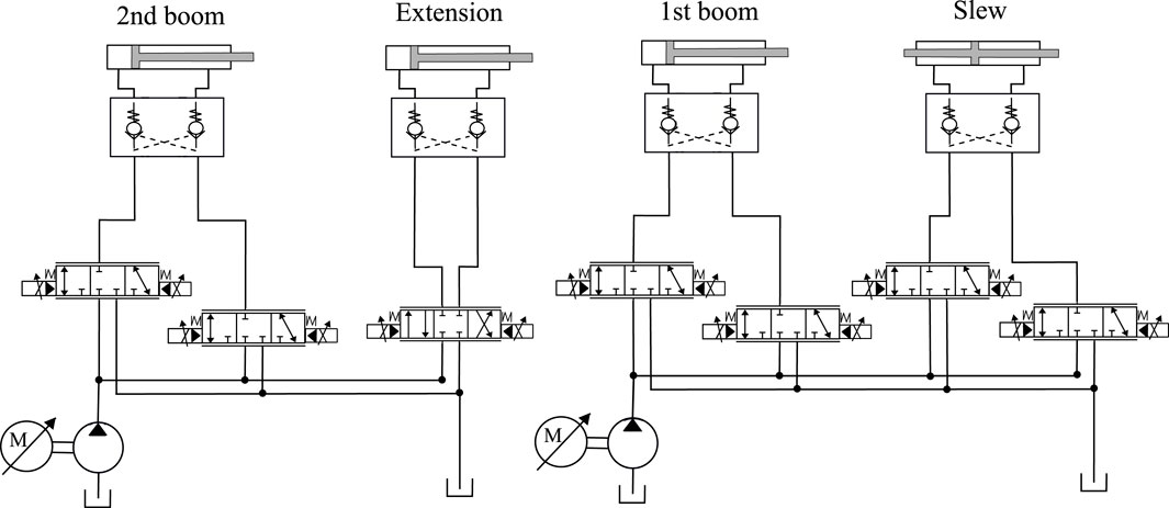
Figure 7. Prototype system with one circuit with second boom and extension, and one with first boom and slew.
Another difference to the reference system is that there are no pressure compensators on the meter-in side. The reason is to examine if the speed control of the cylinders works with a simpler valve but with more advanced control and to gain insights in the flow control of uncompensated spools which are needed for more complex regenerative circuits.
The load holding valves are kept from the reference system. Energy neutral operation is not possible because the load holding valves require a certain pressure on the meter-in side to open up the meter-out side during lowering motions. Recuperation of energy back to the battery is not possible due to pressure reducers in the load holding valves on the meter-out side.
4.5.2.1 Control strategy
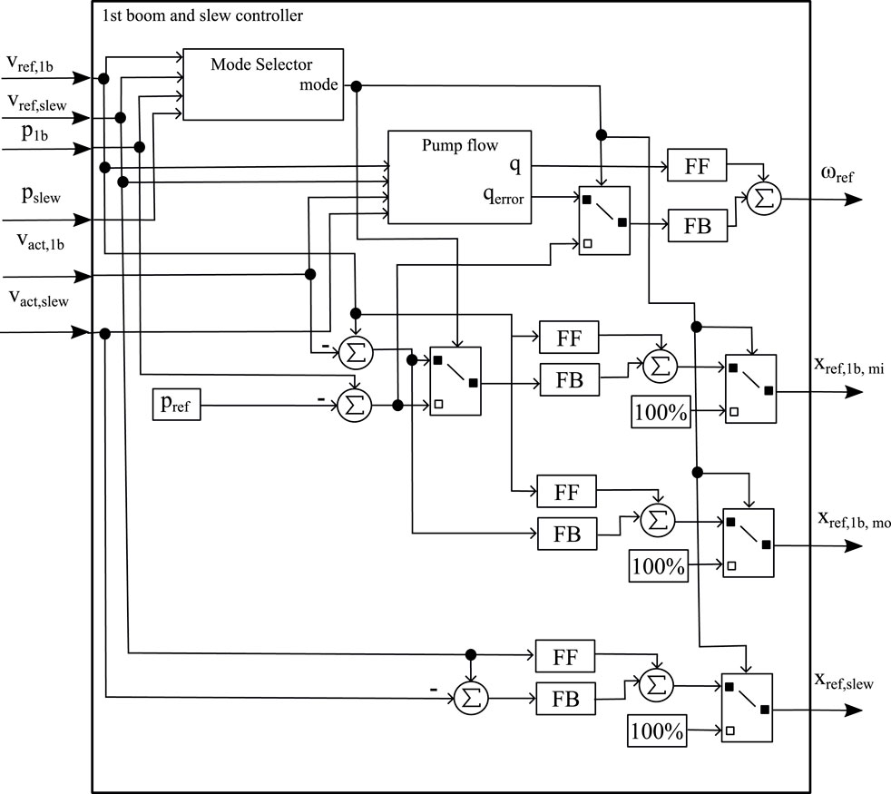
The control strategy of the system has two objectives; to keep the cylinders moving at their reference speeds and to minimize the energy consumption of the system. The two circuits are completely decoupled. Both valve and pump control is used to achieve the objectives. The control structure of the first boom and slew circuit is displayed in Figure 8. The control strategy which is implemented in the Controller block is presented in Figure 9.
When the external force is working against the direction of movement, the speed of the cylinders is controlled by the meter-in flow, otherwise by the meter-out flow. The meter-out flow is always valve controlled when it is controlling the cylinder speed. Since open flow control is used, the meter-in flow is pump controlled for the heaviest load and valve controlled for the other cylinder (if active) on the same circuit.
The valve control is a combination of a feed forward from the reference speed and a feedback of either the error in cylinder speed or the error in the pilot pressure needed to keep the load holding valve open. For the slew and the extension cylinder, the feedback is always cylinder speed. For the first and second boom, the cylinder speed is used for the meter-in valve during lifting motions and for the meter-out valve during lowering motions. The error in pilot-pressure is used for the meter-in valve during lowering motions in order to make sure that just enough flow is sent to the cylinder to keep the load holding valve open. During lifting motions, the meter-out valve is completely open.
A mode selector determines which spools that should be completely open and what type of control should be applied to the others. A more detailed description of the control strategy can be found in Rankka (2023).
4.5.2.2 Results
The demonstrator system was evaluated both during manual control and during automated operation on the drive cycle produced in Rankka et al. (2019). The drive cycle is used to get a representative energy comparison with the reference system and to evaluate the drivability during automatic control. While the drivability during manual control is considered to be quite good, the control system has much more trouble achieving smooth operation during automatic control. For a human operator the exact trajectory of an individual cylinder is not that important as long as the crane does not collide with anything. In order to follow the drive cycle, the control system, however, needs to keep every cylinder following its reference speed at all times. At some parts of the drive cycle the reference following is acceptable, see Figure 10, but in others sections there are some issues, see Figure 11. The issues can be described according to the following:
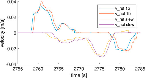
Figure 10. Example of good reference following of first boom and slew cylinder velocities during the drive cycle.
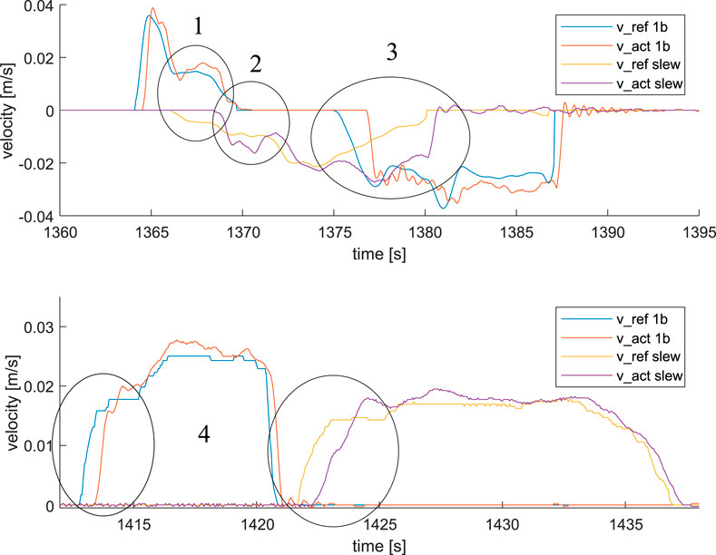
Figure 11. Example of reference following of first boom and slew cylinder velocities during the drive cycle. There are issues with simultaneous operation of first boom and slew (upper) and with delays at start-up (lower).
When heavily loaded, automated operation of the crane was not considered to be safe due to the above mentioned issues being even worse. Thus, only the unloaded part of the drive cycle was evaluated and it is not possible to measure whether the predicted reduction of 15% battery energy on the complete drive cycle is met. The energy efficiencies of the demonstrator system and the reference system can however be compared. The efficiency from valve inlet energy to cylinder energy was 49.4% on the completed part of the cycle for the demonstrator and the efficiency of the reference system was 37.7%.
The static models developed earlier in the project gives an efficiency for the demonstrator system of 56.9% on the same operating points, meaning that the physical system performs 15% worse than predicted. Also the reference system has a lower efficiency than predicted by its model. The model calculations give an efficiency of 41.5%, the physical reference system thus performs 10% worse.
4.5.3 Pump controlled actuator systems
In order to eliminate the losses from simultaneous operation completely, a separate drive unit for each function is required. With good flow control from the drive unit, directional valves are not required and the actuators are completely pump controlled. The system can, however, not be completely valveless. Load holding valves and pressure relief valves are required for safety reasons and for asymmetrical cylinders valves can be needed to control the flow balance, depending on the solution. A system with pump controlled cylinders and electrically controlled load holding valves can lower the energy consumption of the loader crane reference system by 43% (Rankka and Dell’Amico, 2021). If energy is recuperated to the battery whenever the first or second boom is performing a lowering motion, the energy consumption is reduced by 49%.
As part of the Stealth project, pump controlled actuators have been investigated in several studies. Given that these studies have not been applied to the same reference crane as used here, it is not possible to directly compare any numbers, but general results and learnings still apply. Implementations on different construction machines also enable a broader practical understanding of the concept. In this section, results of relevance to the procedure of finding a suitable system for the loader crane reference are presented.
In one study (Edén and Lagerstedt, 2018), a single acting, open circuit, pump controlled cylinder is implemented on the first boom of a small loader crane. The system is able to recuperate energy back to the battery and the efficiency of the recuperation is found to be heavily dependent on the load of the cylinder. One of the learnings was that when releasing the control lever the driver expects the cylinder movement to stop directly, both during upwards and downwards movements. The drive system was too slow to decelerate and the load holding valves had to be used to stop the movements. The study also highlights the fact that when the pump is mounted at some distance from the cylinder, which will most likely be the case on the boom system of the crane, where the energy cost of moving drive units mounted on the booms can be higher than the gain from short hoses, the pressure on both sides of the load holding valves must be equalized before a lowering motion can start to prevent an unexpected drop in cylinder position. The pressure equalizing is done by running the pump in the opposite direction for a short time to build up the pressure between the pump and the load holding valve before starting the lowering motion.
For the second boom of the crane, a double acting system is required to be able to move the cylinder on both sides of the boom’s vertical center line. In another study within the project (Fernlund, 2020), a closed circuit, double acting pump controlled cylinder is implemented on the asymmetric boom cylinder of a backhoe loader. Also this system is able to recuperate energy to the battery and the total efficiency of a lifting-lowering motion is heavily dependent on the flow. A closed loop system on an asymmetric cylinder must be able to compensate for the asymmetric flow so that the pump always has a flow balance. In this study, the compensation is done by a dump valve on the piston side of the cylinder and a boost pump that can be connected to both cylinder sides. The control of the system is open loop and based on the characteristics of the components but the system is still able to follow the reference speed well apart from operating points at high speed and high pressure, where the resulting speed of the cylinder is lower than the reference. To use dump valves and a boost pump introduces energy losses compared to an ideal system with an ideal accumulator controlling the flow balance. The results from a theoretical study in the project (Kärnell et al., 2021) however, shows that for two typical backhoe loader use cases, the energy consumption is only about 10% higher than for the ideal system.
4.6 Comparison and analysis
The last step of the procedure of finding suitable systems for the reference application is to compare the in-depth investigated systems; dual pump system with open flow control and a system with pump-controlled cylinders, in terms of how well they fulfill the requirements and how far they are from becoming commercialized products.
4.6.1 General comparison
Achieving cylinder movements that are without interference of the other cylinder connected to the same circuit has proven to be difficult with for the dual pump system with open flow control. Achieving load independent speed through electrical pressure compensation was likewise difficult and interfering with the open flow control; if one function does not consume exactly the predicted flow, this is immediately shown on the speed of the other function on the same circuit. Consequently, the dual pump system does not, at the current level of development, meet the requirement of having as good drivability as the reference system. From an energy perspective, electrical pressure compensation is not needed for this system layout given that only the lightest of the two functions on a circuit has a compensated flow. It is possible that the drivability would improve by changing to a valve with hydraulic pressure compensation, which would control the flow to the lighter function faster than with the current setup. Electrical pressure compensation is however a requirement for more complex dual pump systems with, for example, regeneration between cylinders.
With pump-controlled cylinders the speed of each cylinder is decoupled from the others. Especially for automated operation there is a big benefit for pump-controlled cylinder systems where the actual speed of the cylinders is more predictable. Less development resources would probably have to be put into making a pump-controlled cylinder system into a commercial product than a dual pump system with energy reduction concepts such as open flow control or regeneration from a drivability point of view.
In order to fulfill the requirement that every single cylinder should be possible to operate at its maximum power, all cylinders in a pump-controlled system can be operated at maximum power take out at the same time, as long as the battery power is sufficient. This is however a drawback when it comes to component efficiencies, drive cycle calculations show that the average working point is far from the peak efficiency and that overall component efficiencies suffer from this. Systems with several cylinders on the same pump can be dimensioned for having the average working point closer to the maximum working point, while still allowing a cylinder to reach its maximum if operated alone. One possible remedy for pump-controlled cylinders is to allow for a different design criteria where the flow is limited at high pressures and using pumps where the displacement can be controlled to a lower value at high pressure demands.
A system with pump-controlled cylinders is very modular but the total weight and required space on the crane or truck are larger than for the dual pump system. When trying to make the crane more efficient in order to make a more sustainable product it is important to bear in mind that if a component reduces the crane consumption slightly, the weight of the component added to the truck is increasing the traction consumption of the truck if the battery size can not be adjusted to match the small efficiency increase. The battery size cannot be arbitrarily small either, it must be large enough to provide the peak power demand of the application.
4.6.2 Component selection
It is noted in both practical studies of pump controlled cylinders, that the drive system components are not optimally sized for the working points of the designated cylinders. Being part of a research project, the demonstrators of the studies are more proof of concepts than commercial solutions, but the problem of finding suitable components is nevertheless important to highlight and just as important for dual pump systems. Components of a commercialized system should:
4.6.3 Energy performance
As can been seen in Figure 11, there are as many as six mode switches during a lifting movement of about 20 s, all of them causing a small disturbance in the speed reference following. In order to mitigate this problem, energy requiring measures, such as delaying open flow activation, might be necessary. According to the static model calculations from the concept screening, systems with two or four pumps can reach up to 50% energy reduction compared to the reference system. However, the dual pump demonstrator, that had a predicted energy reduction of 15% according to the model, did not reach really as good performance during testing as predicted and the problems with achieving good drivability indicate that a system with the additional requirements of regeneration and recuperation needed to reach 50% reduction will be far from ideal. The most energy efficient dual pump system will thus probably not reach that high a reduction. Depending on the solution for compensating for the flow unbalance of asymmetrical cylinders, pump-controlled system will perform a bit from the ideal value as well but is still considered to be the winning system in terms of energy efficiency in practice.
Even though the drive cycle could not be completed with the dual pump demonstrator and an exact answer is not possible to give, the energy performance difference to the model prediction indicate that the project target of 15% reduction would probably not have been met. One thing that could further increase the efficiency is automated control with an energy efficiency objective. When freedom in how to move the crane between two waypoints is introduced, losses from simultaneous operation can be minimized by operating only one function at a time on each pump as much as possible. This would also improve the drivability of the system. Finding strategies for energy efficient automation that makes the most out of a given system will be the subject for further research.
5 Conclusion
This paper presents a new framework of designing an energy efficient hydraulic system. Applying the proposed framework to the case study of finding the system that best meet the requirements of a loader crane application has resulted in valuable insights in the challenges and opportunities of different systems, and how well they meet the different requirements.
The results from the concept exploration phase show that two different types of systems, in their most extreme setups, have the potential to reach 50% energy reduction compared to the load sensing reference system. Both system types are investigated further in the System design analysis through demonstrators phase. The tested systems are not of the most extreme setups, but according to the simulations, they would meet the project goal of 15% energy reduction.
Tests show that the dual pump demonstrator with open flow control does not reach the same energy performance as the simulated system, and given that in order to get maximal energy performance an even more complex system would be required, the most energy efficient of the systems investigated in this project is most likely the pump-controlled cylinder system. Less effort is also required to get acceptable drivability with this system compared to the most energy efficient system with only two pumps. Even so, the issue of designing the drive system to be compact, light and cost-effective, might delay its possible commercialization. Regarding load holding capabilities, the pump controlled demonstrator on a loader crane show that load holding with electrical on-off valves is possible but that further development is needed before the legal requirements are met in practice.
For future studies, it would be interesting to expand the design space to include also the design of the cylinders and the hoses and couplings. It would also be interesting to look at the problem of reducing the energy consumption from another angle. Instead of optimizing the system with regards to a human operator, automated control could be considered and optimized with regards to the system design.
Data availability statement
The data analyzed in this study is subject to the following licenses/restrictions: The dataset is proprietary data of Hiab. The measurement signals are defined in the paper where the dataset is originally used (referenced from this paper). Requests to access these datasets should be directed to Amy Rankka, YW15LnJhbmtrYUBsaXUuc2U=.
Author contributions
AR: Conceptualization, Formal Analysis, Investigation, Methodology, Writing–original draft. AD: Funding acquisition, Project administration, Supervision, Writing–review and editing.
Funding
The author(s) declare that financial support was received for the research, authorship, and/or publication of this article. This work was jointly funded by the Swedish Energy Agency (App. no 44427-1) and the participating partners in project Stealth, Sustainable Electrified Load Handling.
Acknowledgments
The authors would like to acknowledge the contribution from the participating partners in project Stealth (Swedish Energy Agency App. no 44427-1).
Conflict of interest
Author AR was employed by Hiab AB.
The remaining author declares that the research was conducted in the absence of any commercial or financial relationships that could be construed as a potential conflict of interest.
Publisher’s note
All claims expressed in this article are solely those of the authors and do not necessarily represent those of their affiliated organizations, or those of the publisher, the editors and the reviewers. Any product that may be evaluated in this article, or claim that may be made by its manufacturer, is not guaranteed or endorsed by the publisher.
References
Axin, M., Eriksson, B., and Palmberg, J.-O. (2009). “Energy efficient load adapting system without load sensing - design and evaluation,” in The 11th Scandinavian International Conference on Fluid Power.
Bedotti, A., Pastori, M., and Casoli, P. (2018). “Modelling and energy comparison of system layouts for a hydraulic excavator,” in 73rd Conference of the Italian Thermal Machines Engineering Association, 26–33.
Bury, P., Stosiak, M., Urbanowicz, K., Kodura, A., Kubrak, M., and Malesińska, A. (2022). A case study of open-and closed-loop control of hydrostatic transmission with proportional valve start-up process. Energies 15, 1860. doi:10.3390/en15051860
Edén, J., and Lagerstedt, F. (2018). An electro-hydraulically controlled cylinder on a loader crane. Linköping, Sweden: Linköping University Electronic Press.
Eriksson, B. (2010). Mobile fluid power systems design with a focus on energy efficiency. Linköping, Sweden: Linköping University Electronic Press.
Fernlund, E. (2020). A novel pump-controlled asymmetric cylinder with electric regeneration - implementation and evaluation of a closed hydraulic system on a backhoe. Linköping, Sweden: Linköping Univeristy Electronic Press.
Finzel, R., Helduser, S., and Jang, D.-S. (2010). “Electro-hydraulic dual-circuit system to improve the energy efficiency of mobile machines,” in 7th International Fluid Power Conference, 1–13.
Hagen, D., Padovani, D., and Choux, M. (2019a). A comparison study of a novel self-contained electro-hydraulic cylinder versus a conventional valve-controlled actuator-part 1: motion control. Actuators 8, 79. doi:10.3390/ACT8040079
Hagen, D., Padovani, D., and Choux, M. (2019b). A comparison study of a novel self-contained electro-hydraulic cylinder versus a conventional valve-controlled actuator-part 2: energy efficiency. Actuators 8, 78. doi:10.3390/ACT8040078
Heybroek, K. (2017). On energy efficient mobile hydraulic systems with focus on linear actuation. Linköping Studies in Science and Technology Dissertations. Linköping: Linköping Universtity Electronic Press.
Heybroek, K., and Sahlman, M. (2018). A hydraulic hybrid excavator based on multi-chamber cylinders and secondary control–design and experimental validation. Int. J. Fluid Power 19, 91–105. doi:10.1080/14399776.2018.1447065
Imam, A., Rafiq, M., Jalayeri, E., and Sepehri, N. (2018). A pump-controlled circuit for single-rod cylinders that incorporates limited throttling compensating valves. Actuators 7, 13. doi:10.3390/act7020013
Jiao, Z., Yu, B., Wu, S., Shang, Y., Huang, H., Tang, Z., et al. (2019). An intelligent design method for actuation system architecture optimization for more electrical aircraft. Aerosp. Sci. Technol. 93, 105079. doi:10.1016/j.ast.2019.03.048
Kärnell, S., Fernlund, E., Lagerstedt, F., and Ericson, L. (2021). “Pump-controlled actuators with dump valves,” in The 17th Scandinavian International Conference on Fluid Power, 150–160.
Karpenko, M., Stosiak, M., Šarūnas, Š., Skačkauskas, P., Urbanowicz, K., and Deptuła, A. (2023). Hydrodynamic processes in angular fitting connections of a transport machine’s hydraulic drive. Machines 11, 355. doi:10.3390/machines11030355
Malmquist, D., Frede, D., and Wikander, J. (2014). Holistic design methodology for mechatronic systems. Proc. Institution Mech. Eng. Part I J. Syst. Control Eng. 228, 741–757. doi:10.1177/0959651814527936
Mhenni, F., Choley, J. Y., Penas, O., Plateaux, R., and Hammadi, M. (2014). A sysml-based methodology for mechatronic systems architectural design. Adv. Eng. Inf. 28, 218–231. doi:10.1016/j.aei.2014.03.006
Moerland, E. (2013). Collaborative understanding of disciplinary correlations using a low-fidelity physics based aerospace toolkit. Proc. 4th CEAS Conf. doi:10.5281/zenodo.546693
Opgenoorth, A., and Schmitz, K. (2023). “Algorithm based system synthesis of electrified mobile machines,” in The 18th Scandinavian International Conference on Fluid Power.
Opgenoorth, A., Sender, B., and Schmitz, K. (2022). “Switching procedures of multi-pressure systems for electrified excavators,” in The 13th International Fluid Power Conference.
Pedersen, H. C., Bender, N. C., and Andersen, T. O. (2023). Investigating the design parameters’ influence in a fast switching valve - an approach to simplify the design process. Int. J. Fluid Power 24, 247–270. doi:10.13052/ijfp1439-9776.2424
Rankka, A. (2023). Electrification of load handling hydraulic systems: with a focus on loader cranes. Linköping, Sweden: Linköping University Electronic Press.
Rankka, A., and Dell’Amico, A. (2021). “Loss analysis and concept comparison for electrically driven hydraulic loader crane,” in The 17th Scandinavian International Conference on Fluid Power, 237–251.
Rankka, A., Dell’Amico, A., and Krus, P. (2019). “Drive cycle generation for a hydraulic loader crane,” in The 16th Scandinavian International Conference of Fluid Power.
Salutagi, S. S., Kulkarni, M. S., and Kulkarni, A. (2016). Use of cfd technology in hydraulics system design for off-highway equipment and applications. Int. J. Mater. Mech. Manuf. 4, 52–55. doi:10.7763/ijmmm.2016.v4.224
Scherer, M., Geimer, M., and Weiss, B. (2013). “Contribution on control strategies of flow-on-demand hydraulic circuits,” in The 13th Scandinavian International Conference on Fluid Power, 531–540.
Shenouda, A. (2006). “Quasi-static hydraulic control systems and energy savings potential using independent metering four-valve assembly configuration,”. Georgia Institute of Technology. Dissertations.
Siebert, J., Wydra, M., and Geimer, M. (2017). Efficiency improved load sensing system - reduction of system inherent pressure losses. Energies 10, 941. doi:10.3390/en10070941
Staack, I., Amadori, K., and Jouannet, C. (2019). A holistic engineering approach to aeronautical product development. Aeronautical J. 123, 1545–1560. doi:10.1017/aer.2019.51
Stosiak, M., and Karpenko, M. (2024). The influence of the hydropneumatic accumulator on the dynamic and noise of the hydrostatic drive operation. Eksploatacja i Niezawodnosc - Maintenance Reliab. 26. doi:10.17531/ein/186169
Vukovic, M., and Leifeld, R. (2016). “Steam-a hydraulic hybrid architecture for excavators,” in 10th International Fluid Power Conference.
Keywords: energy efficiency, electrification, mobile hydraulic systems, system design, design exploration
Citation: Rankka A and Dell’Amico A (2024) Procedure of developing more energy efficient and electrified hydraulic systems for loader cranes. Front. Mech. Eng. 10:1494642. doi: 10.3389/fmech.2024.1494642
Received: 11 September 2024; Accepted: 22 October 2024;
Published: 06 November 2024.
Edited by:
Gustavo Koury Costa, Federal Institute of Pernambuco, BrazilReviewed by:
Michał Stosiak, Wroclaw University of Science and Technology, PolandMykola Karpenko, Vilnius Gediminas Technical University, Lithuania
Copyright © 2024 Rankka and Dell’Amico. This is an open-access article distributed under the terms of the Creative Commons Attribution License (CC BY). The use, distribution or reproduction in other forums is permitted, provided the original author(s) and the copyright owner(s) are credited and that the original publication in this journal is cited, in accordance with accepted academic practice. No use, distribution or reproduction is permitted which does not comply with these terms.
*Correspondence: Amy Rankka, YW15LnJhbmtrYUBsaXUuc2U=
 Amy Rankka
 Alessandro Dell’Amico1