- 1Department Mechanical Systems Engineering, Tokai University, Hiratuka, Japan
- 2Department Mechanical Systems Engineering (Former Student), Tokai University, Hiratuka, Japan
This study investigates the impact of incorporating an Inner Ring Groove (IRG) on the leakage characteristics of dry gas seals, commonly used in turbomachinery such as gas turbines and compressors. The primary objective is to enhance sealing performance and reduce gas leakage, which is critical for improving the efficiency of these machines. The research focuses on various groove shapes, including spiral grooves for single-direction rotation and T-grooves and tree grooves for bi-directional rotation. The experimental setup involved measuring air leakage rates across different seal configurations, both with and without the IRG. The results indicated that while the IRG increased leakage in spiral groove seals, it significantly reduced leakage in T-groove and tree groove seals. Specifically, the IRG reduced leakage by approximately 26% in T-groove seals and 15.8% in tree groove seals, compared to their standard configurations. Additionally, the study employed Particle Image Velocimetry (PIV) to visualize gas flow within the seal gaps. The visualization revealed that the IRG altered the flow dynamics, particularly in T-groove seals, where it redirected the gas flow from a radial to a circumferential direction, thereby reducing leakage. In contrast, the IRG in spiral groove seals promoted radial flow, leading to increased leakage. These findings suggest that the application of IRGs can be particularly effective in bi-directional rotation seals, offering a potential design modification to enhance sealing performance. The study concludes that while IRGs may not be suitable for all groove types, their strategic application can lead to significant improvements in leakage reduction and overall efficiency of dry gas seals.
1 Introduction
Turbomachinery, such as gas turbines and compressors, are applied to various applications including power plants and transporting systems. Consequently, there is a pressing need to conserve energy and enhance the efficiency of these devices. One approach to augmenting the mechanical efficiency of gas turbines is to increase the compressor’s compression ratio. A critical aspect of this is preventing the air compressed by the compressor from leaking into the atmosphere. It has been reported that a 1% reduction in gas leakage from the shaft seal can lead to a 1.7% improvement in engine efficiency for aircraft jet engine compressors (Wilcock et al., 1968). Recently, the supercritical carbon dioxide (sCO2) turbomachinery is the one of the most expected application (Laxander et al., 2019; Zhang et al., 2024; Yuan et al., 2024). As a result, many researcher and engineers are focused on dry gas seals which is known for their minimal gas leakage compared to other non-contact seals.
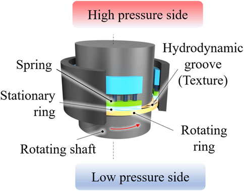
The outline of a dry gas seal is shown in Figure 1 The dry gas seal consists of four main components: a rotating ring, a stationary ring, a spring, and a housing. The rotating ring, equipped with grooves, spins at high velocity to create hydrodynamic pressure and form an air film (Stahley, 2005; Zhang et al., 2024). The performance characteristics of dry gas seals are significantly influenced by the configuration of the hydrodynamic grooves (Chen et al., 1969; Green and Barnsby, 2001; Etsion, 2005; Shahina et al., 2013; Chen, 2024), prompting research into groove shape optimization to improve some characteristics (Hashimoto and Ochiai, 2008; Wang and Chen, 2009; Papadopoulos et al., 2011; Ochiai et al., 2014; Cong et al., 2022; Ochiai and Sato, 2022c).
It is known that the optimized groove designs aimed at minimizing air leakage exhibit superior sealing capabilities. However, sometimes their complex configurations lead to high-precision machining, potentially escalating production costs. Nonetheless, form the one of the optimization results obtained by the cell automaton proposed by the authors reveals a simple ring-shaped groove within a complex structure (Ochiai et al., 2018). This discovery led the author to hypothesize that applying the inner ring groove to previously utilized groove shapes could effectively suppress air leakage. Li et al. analyzed a dry gas seal with grooves in which the spiral groove and the inner ring groove are in, and found that the operation is stable at low speeds and high pressures, but the lifting force is lower and air leakage is increased compared to spiral groove seals (Li et al., 2013). However, there are no studies that apply inner ring grooves to groove shapes in which the inner ring groove and the spiral groove are independent, or to bi-rotating dry gas seals, for example, T-groove shapes. Furthermore, there are no studies that consider the visualization of air flowing through the seal surface when an inner ring groove is applied.
In recent years, Particle Image Velocimetry (PIV) has been applied to fluid lubrication to know the tribological characteristics more specifically (Green et al., 2011; Li et al., 2012; Emden et al., 2016; Richardson et al., 2019). This is a promising method in the field of fluid film lubrication and its applications. Despite the widespread use of Particle Image Velocimetry (PIV) as a flow visualization technique, there have been few instances of its application in Dry gas seals (Suzuki et al., 2016; Ochiai et al., 2019). This is presumably due to the need to capture flow moving at high speeds within extremely thin gaps. However, as previously mentioned, with the recent advancements in measurement equipment and methodologies, it is believed that the application of PIV to fluid lubrication has become possible. Indeed, the authors conducted the PIV analysis against the liquid type of mechanical seals and clarified the effect of rotational direction on leakage characteristics (Ochiai and Sato, 2022a) and the effect of temperature it leads to thermal distortion of seal surfaces comparing the three types of grooved seals (Ochiai and Sato, 2022b). Same as optimization research, it is important to visualize and recognize the actual gas flow between seal surfaces.
Under the background, this study conducted experiments to measure air leakage by incorporating an inner ring groove (IRG) into several types of groove shapes: the spiral groove, typically used for single-direction rotation, and the T-groove and tree groove, suitable for bi-directional rotation. Because the bi-directional rotation type seals are usually inferior to single-directional type seals. Moreover, by using the PIV analysis method of gas lubrication film, comparison of the gas flow vector of the spiral groove seal with T-groove seal was conducted for understanding the mechanism of the inner ring groove (IRG) on the sealing effects.
2 Test seals
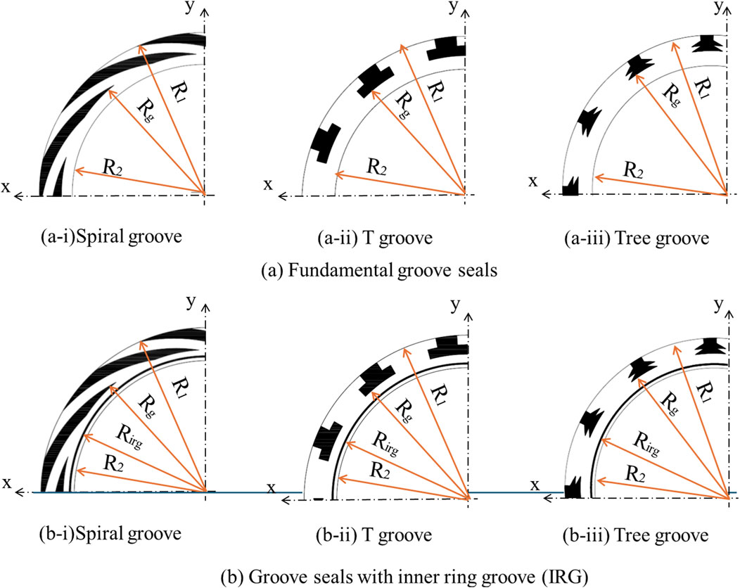
To ascertain the impact of the inner ring groove, a comparative analysis of six types of seals is conducted. This included three conventional basic seals and seals equipped with newly proposed inner ring grooves. The seal depicted in Figure 2A is a standard seal, while the seal in (a-i) represents a common spiral groove seal designed for single rotation. Conversely, the seals in (a-ii) and (a-iii) are T-groove seals and Tree globe seals, respectively, both designed for bi-directional rotation. Here, R1 denotes the outer radius of the test seal, R2 signifies the inner radius of the test seal, and RS represents the inner radius of the groove, which we refer to as the seal radius.
In Figure 2B, a thin groove is incorporated on the inner circumferential side of each seal shown in (a). This groove is referred to as the “inner circumference ring groove” throughout this paper. The term Hi, as shown in each figure, indicates the inner radius of the inner circumferential ring groove. The dimensions of each test seal are provided in Table 1.
3 Gas leakage measurement
3.1 Experimental apparatus for amount of gas leakage
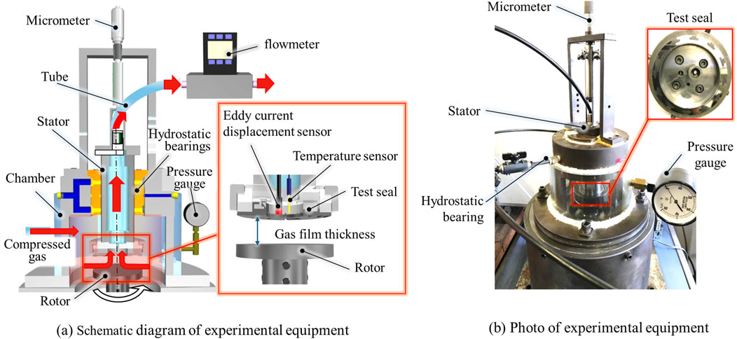
A schematic diagram of the experimental apparatus utilized in this study is depicted in Figure 3A, while an external photograph is presented in Figure 3B. A rotor is mounted at the base of this apparatus. It is comprised of a direct drive with an integrated motor, capable of high-speed rotation. The runout around the rotor is constrained to within 5 μm.
The upper section of the rotor houses the test seal portion, as illustrated in the magnified image in the figure. A gas film is established between the rotor and the test seal surface. An eddy-current displacement sensor is installed within the test seal to gauge the thickness of the gas film. The accuracy of the displacement sensor is 1 μm. A temperature sensor is also incorporated, which is utilized to adjust for the temperature of the eddy-current displacement sensor. The thickness of the gas film can be modified by a micrometer located at the top of the apparatus.
The test seal section is encased within a chamber, to which compressed gas is supplied externally. The pressure within the chamber can be assessed with the pressure gauge depicted in the figure. The compressed gas within the chamber escapes to the inner diameter side of the seal via the gas film formed between the rotor and the test seal surface. The leaked gas travels the interior of the sealed stator and is measured by the flowmeter located in the middle. The test seal can be changed using the attachment, the test seal was appropriately replaced with one of a different groove shape, and the amount of gas leakage was measured.
3.2 Experimental method for amount of gas leakage
In this experiment, the amount of air leakage was measured under changing the air film thickness. Initially, air was supplied from the compressor until the pressure within the chamber reached 25 kPa. Subsequently, the height of the test seal can be manipulated using a micrometer, thereby adjusting the thickness of the air film to a predetermined value. The rotor was then set in motion at a speed of 20,000 rpm, and the amount of leakage was measured using a flow meter (M-500, Japan Star Techno Co., Ltd.). The measurement range is 2.5–500 L/min and the accuracy is 0.8% reading + 0.2% full scale. Using this methodology, the thickness of the air film was systematically reduced from 30 μm to 18 μm in increments of 2 μm, and at each stage, 20 separate measurements of the leakage rate was conducted. The thickness of the experiment is large compared with actual dry gas seals, however the ratio of the groove depth hg and gas film thickness h, hg/h, is 0.45–0.27 and the obtained tendency from the experiment are applicable to actual applications.
3.3 Experimental results in amount of gas leakage
Initially, we examined the correlation between the leakage rate and the gas film thickness for three types of seals, which are fundamental shapes: the single-rotation spiral groove seal, the T-groove seal, and the Tree groove seal, all of which are designed for bi-directional rotation.
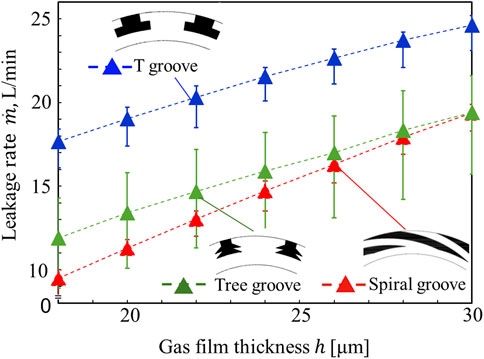
Figure 4 shows the experimental results of amount of gas leakage. Each data plot signifies the average leakage rate following 20 measurements, with the error bars indicating the maximum and minimum measured values. A direct increase in the seal clearance significantly impacts the leakage rate. Comparing the three types of seals, it is evident that the single-rotation spiral groove seal exhibits the least leakage, followed by the tree groove seal. In contrast, the T-groove seal has a considerably higher leakage rate, indicating inferior sealing characteristics. However, since the spiral groove seal cannot generate hydrodynamic pressure during reverse rotation, both rotating grooves offer an advantage, and a bi-directional rotation seal groove may be chosen depending on the machine in use. Regarding the tree groove seal, when the film thickness is substantial, the leakage volume is comparable to that of the spiral groove seal, suggesting its superiority over the T-groove seal.
Then, we compare the leakage quantities with and without inner circumferential ring grooves (IRGs) are incorporated. The results are depicted in Figure 5A, which illustrates the comparative results for a spiral groove configuration. It has been confirmed that the application of an inner ring groove (IRG) to the spiral groove leads to increase of gas leakage. Specifically, when the inner ring groove is present, the larger gas film thickness experiences an increase of leakage rate. This enhancement of amount of gas leakage is nearly identical for a measured wide range of gas film thickness, averaging an increase of 9.3%. In addition, it is suggested that the same tendency remains in thinner gas film same as actual dry gas seals from tendency of this graph. This The underlying rationale can be attributed to the following mechanism: primarily, the leakage quantity originates from the pressure differential across the inner and outer peripheries of the seal interface. Moreover, the presence of a groove on the sealing surface introduces dynamic pressure effects, which in turn generate a pressure distribution impacting the leakage rate. Fundamentally, within the spiral groove, the dynamic pressure induced by the pumped-in flow effect—propelled by rotational motion—is postulated to influence the gas leakage phenomenon.
Conversely, when the inner ring groove is integrated into the T-groove, as illustrated in Figure 5B, a significant reduction in air leakage is confirmed. Quantitatively, the incorporation of the inner ring groove results in an average leakage decreases of approximately 26.0% relative to the fundamental groove configuration without the inner ring groove (IRG). This finding underscores the effectiveness of the inner ring groove in enhancing the sealing performance of T-groove structures. It is quite close to the leakage rate of a fundamental spiral groove seal and it is suggested that the same tendency remains in thinner gas film.
The obtained results can be considered as follows: Within the T-groove configuration, the feature of both rotations generate negative pressure in conjunction with positive pressure to counteract reverse rotation. However, due to the relatively weak generation of positive pressure in the T-groove, the predominant effect of bi-directional rotation is leads to gas flow into the seal interface from the high-pressure outer periphery, resulting in increased leakage with a standard T-groove seal. Conversely, it is considered that the implementation of an inner ring groove (IRG) induces a modification in the flow near the seal’s inner circumference, thereby mitigating gas leakage into the seal. This suggests that further research from alternative perspectives may yield additional insights.
Finally, we compared the results of the air leakage measurement experiment when the inner circumferential ring groove was integrated into the tree groove—a groove configuration designed for bi-directional rotation. As depicted in Figure 5C, a significant reduction in leakage is observed with the inner circumferential ring groove compared to the standard tree groove, with an average decrease of approximately 15.8%. Seals featuring tree grooves with IRG not only demonstrated the average leakage rate reduction but also maintained this low rate even at a gas film thickness of h = 30 μm, which is the largest among measured film thickness. Moreover, for a wide measured range of gas film thickness, tree groove with IRG remains most low leakage. However, this advantage might not be remained in thinner area except the measured area. On the other hand, it is suggested that the effect of IRG on tree groove remains in thinner gas film same as T-groove seal.
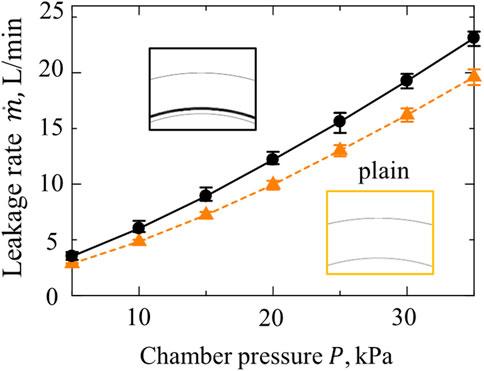
These findings conclusively demonstrate that the inner ring groove (IRG) contributes to air leakage reduction when applied to a groove designed for dual rotation, thereby enhancing the sealing performance to equal or exceed that of spiral grooves intended for typical single-direction rotation. Then, we specifically investigated the impact of the inner circumferential ring groove (IRG) in isolation. To this end, we measured the leakage rates of a plain seal without any grooves and a seal equipped solely with the IRG. Throughout these experiments, the gas film thickness was maintained at h = 18μm, while the chamber pressure varied from 5 kPa to 35 kPa. The results, as illustrated in Figure 6, indicate that the gas leakage rate increases with increasing chamber pressure. Notably, at all tested pressures, the seal with the inner ring groove exhibited higher leakage than the plain seal. With the inner ring groove (IRG) alone, it promotes radial flow and gas leakage.
4 Visualization of flow in dry gas seals
To elucidate the reasons behind these intriguing findings, we tried to visualize the gas flowing in the seal clearance.
4.1 Experimental apparatus for flow visualization and test method
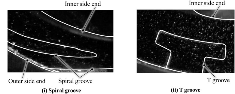
Figure 7A illustrates a schematic diagram of the visualization apparatus, while Figure 7B presents a photograph of the external appearance of the same device. In this experiment, we visualized the airflow through the seal clearance during rotor operation. Initially, we established the zero point of the eddy current displacement transducer by bringing it into contact with the test seal and the rotor in a stationary state. Subsequently, the test seal was secured within an acrylic case, which was then pressurized to 5 kPa. We regulated the rotor’s rotational speed to 3,000 rpm at a clearance of 80 μm, and directed a 2 W sheet laser into the gap between the test seal and the rotor. Following this, tracer particles were introduced into the acrylic case, and a high-speed camera positioned atop the case captured the gas flow through the seal gap as shown in Figure 8. A total of 2,000 frames—equivalent to three full rotations of the rotor—were recorded and analysed using Particle Image Velocimetry (PIV). For this phase of the study, a spiral groove seal was chosen to represent single-direction rotation seals, and a T-groove seal was selected for bi-directional rotation seals. The experiment aimed to compare the influence of the Inner Ring Groove (IRG) on air leakage around the inner circumference.
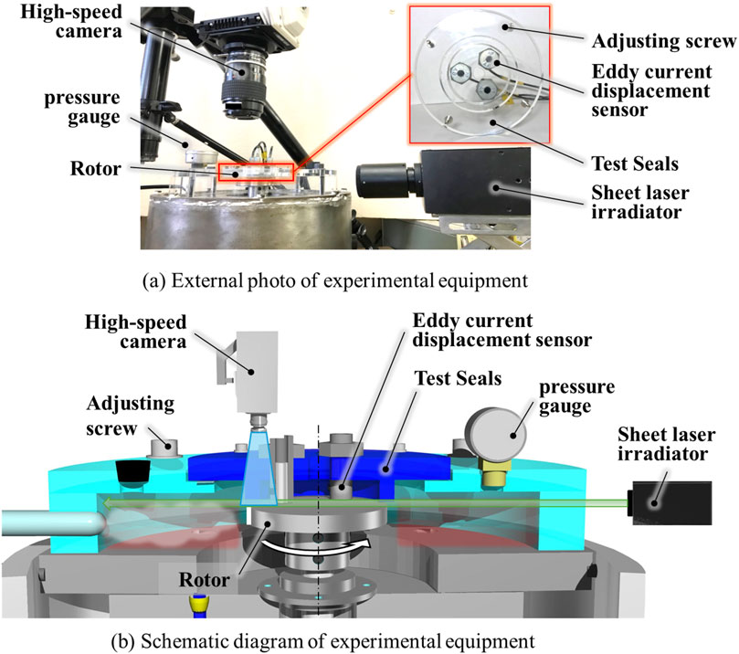
Figure 7. Outline of the experimental equipment for visualization (A) External photo of experimental equipment. (B) Schematic diagram of experimental equipment.
4.2 Visualization results
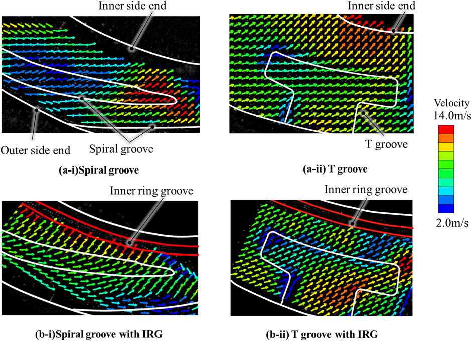
The gas flow visualization results of the four types of test seals are shown in Figure 9. Firstly, from the visualization results of velocity vector in Figure 9 (a-i), it is primarily observed that the flow is in the diagonal direction on the spiral groove seal. This is due to the combined effect of the radial flow, which is caused by the pressure difference from the outer periphery to the inner periphery, and the hydrodynamic pressure effect of the groove due to rotation. Outside of the spiral groove, which is observed obliquely lower area in the figure, the circumferential gas flow is dominant. However, the flow varies to follow the groove as it approaches the groove. Conversely, in the flow that enters the groove, the direction of the flow slightly shifts inward, and this flow direction is generally maintained even after exiting the groove. The velocity magnitude increases slightly with the inner flow exiting the groove.
Additionally, a warm color vector is observed near the tip of the spiral groove, indicating that the flow near the tip has the highest velocity. It is evident how the flow is accelerated within the groove. The gas that exits the tip of the groove appears to flow slightly in the radial direction and exits the interior of the sealing surface while maintaining a relatively high velocity. Generally, the amount of leakage in this vicinity is large, but in other larger areas, the flow is slow in the diagonal direction, suggesting that leakage can be suppressed. In this image, the flow that passes through the interior have not been able to confirm, but it is considered that the above interpretation generally accurate.
Indeed, in the T-groove seal with the basic shape depicted in Figure 9 (b-i), the gas flow significantly differs from that of the spiral groove. Initially, on the outer circumference of the seal, the diagonal flow has already been observed around the outer periphery, and additionally the flow direction is closer in the radial direction compared to the spiral groove. It is noted that the gas flow entering the T-groove slightly alters its direction within the groove. However, upon exiting the groove, it is strongly redirected in the radial direction again and exits inward at a high speed. In comparison to the spiral groove, the warm color area on the inner circumference of the seal is also broader, which is considered contributing to the increase in the amount of leakage.
Then, the impact of the inner circumferential ring groove (IRG) is considered based on the visualization results depicted in Figure 9 (a-ii) and (b-11). Initially, for the spiral groove seal with an IRG as shown in Figure 9 (a-ii), the cold color velocity vector is diminished across the entire sealing surface, and the flow is generally faster. The most characteristic feature is that the gas flow, after traversing the inner circumferential side of the spiral groove, undergoes a strong change in the radial direction and accelerates such that it is drawn into the IRG. In the absence of an IRG, it was possible to suppress the flow to a slow, diagonal direction due to the effect of the spiral groove. However, the installation of an IRG altered the flow direction, which further increased the speed. The flow itself through the inner groove cannot be captured, but it is believed that significant amount of gas is leaking internally due to this flow.
On the other hand, in the double-rotating T-groove, the flow is slightly more intense in the radial direction inside the T-groove due to the influence of the IRG. However, the gas flow that exits the T-groove inward is slightly decelerated, and its direction is also more circumferential compared to the case without an IRG. In the case of the T-groove, the IRG guides the gas flow in the direction of rotation, which is also contribute to the reduction of gas leakage. As depicted in Figure 5 in Chapter 3, it is interesting to note that the flow of the spiral groove without an IRG and the T-groove with an IRG tend to be generally similar.
As described above, from a visualization perspective, we have examined why the Inner Ring Groove (IRG) effect was observed in the T-groove for both rotations, while the IRG was not effective in the spiral groove seal for single rotation. Although the tree groove was not implemented in this instance, the effect of the IRG on the flow is fundamentally considered to be equivalent to that of the T-groove.
5 Conclusion
In this study, we experimentally compared the amount of leakage when a simple ring-shaped groove (IRG) was applied to the spiral groove, which is a usual single-rotation seal for dry gas seals, and the T-groove and tree groove for both rotations. In addition, in spiral groove seals and T-groove seals with and without IRG, the gas flow in the seal gap was visualized, and the relationship with the leakage amount was considered. The conclusions reached are as follows.
As a result of comparing the leakage amount of the spiral groove seal for single rotation, the T-groove seal for both rotation, and the tree groove seal, it was confirmed that the spiral groove seal has the lowest gas leakage amount within the experimental range.
When the Inner Ring Groove (IRG) was applied to the spiral groove seal, an increase in the amount of gas leakage was observed. This suggests that the application of an IRG to the spiral groove seal may not be effective in reducing gas leakage.
In the case of the T-groove seal and the tree groove seal, which are both double-rotating grooves, the application of the Inner Ring Groove (IRG) resulted in a significant reduction in the amount of leakage. The leakage rate of the T-groove seal was found to be equivalent to that of the spiral groove seal without an IRG. Interestingly, the leakage rate of the tree groove seal with an IRG was even lower than that of the spiral groove seal. This suggests that the application of an IRG can be particularly effective in double-rotating groove seals.
Based on the visualization of the gas flow within the seal gap, in the spiral groove seal for single rotation, the influence of the Inner Ring Groove (IRG) promoted the flow towards the inner side of the seal surface, leading to an increase in leakage.
In contrast, in the T-groove seal, the influence of the IRG changed the gas flow from the radial direction to the rotational direction, and the speed also decreased. This is thought to have led to a reduction in leakage. These findings provide valuable insights into the design modifications of the addition of an IRG.
These conclusions are applied under our test conditions which are relatively large gas film thickness. However, there is possible to obtain the same tendency in the actual dry gas seals. It is expected to be examined under the actual conditions, for instance in industries.
Data availability statement
The datasets presented in this study can be found in online repositories. The names of the repository/repositories and accession number(s) can be found in the article/supplementary material.
Author contributions
MO: Writing–original draft, Writing–review and editing, Conceptualization, Funding acquisition, Investigation, Project administration, Supervision, Validation. YO: Writing–original draft, Data curation, Visualization.
Funding
The author(s) declare that financial support was received for the research, authorship, and/or publication of this article. This work was supported by JSPS KAKENHI Grant Number JP16K06050.
Conflict of interest
The authors declare that the research was conducted in the absence of any commercial or financial relationships that could be construed as a potential conflict of interest.
Publisher’s note
All claims expressed in this article are solely those of the authors and do not necessarily represent those of their affiliated organizations, or those of the publisher, the editors and the reviewers. Any product that may be evaluated in this article, or claim that may be made by its manufacturer, is not guaranteed or endorsed by the publisher.
Supplementary material
The Supplementary Material for this article can be found online at: https://www.frontiersin.org/articles/10.3389/fmech.2024.1488803/full#supplementary-material
References
Chen, D. (2024). Influence of microtextured parameters of dry gas sealing rings on tribological performance. Industrial Lubr. Tribol. 76, 4464–4473. doi:10.1108/ILT-12-2023-0389
Chen, H., Castelli, S. V., and Chow, C. Y. (1969). Performance characteristics of spiral-groove and shrouded Rayleigh step profiles for high-speed noncontacting gas seals. Trans. ASME. J. Tribol., 60–68. doi:10.1115/1.3554900
Cong, Z., Jinbo, J., Wenjing, Z., Jie, J., and Xudong, P. (2022). A comprehensive multi-objective, multi-parameter and multi-condition optimization of a spiral groove in dry gas seals. J. Braz. Soc. Mech. Sci. Eng. 44, 206. doi:10.1007/s40430-022-03527-6
Emden, E. V., Venner, C. H., and Morales-Espejet, G. E. (2016). Aspects of flow and cavitation around an EHL contact. Tribol. Int. 95, 435–448. doi:10.1016/j.triboint.2015.11.042
Etsion, I. (2005). State of the art in laser surface texturing. J. Tribol. 127 (1), 248–253. doi:10.1115/1.1828070
Green, I., and Barnsby, M. R. A. (2001). A simultaneous numerical solution for the lubrication and dynamic stability of noncontacting gas face seals. J. Tribol. 123 (1), 388–394. doi:10.1115/1.1308020
Green, T. M., Baart, P., Westerberg, L. G., Lundstrom, T. S., Hoglund, E., Lung, P. M., et al. (2011). A new method to visualize grease flow in a double restriction seal using microparticle image Velocimetry. Tribol. Trans. 54, 784–792. doi:10.1080/10402004.2011.604759
Hashimoto, H., and Ochiai, M. (2008). Optimization of groove geometry for thrust air bearing to maximize bearing stiffness. Trans. ASME, J. Tribol. 130 (3), 031101. doi:10.1115/1.2913546
Laxander, A., Fesl, A., and Hellmig, B. (2019). Development and testing of dry gas seals for turbomachinery in multiphase Co2 applications, Engineering. Environ. Sci. doi:10.17185/duepublico/48878
Li, J. X., Hoglund, E., Westerberg, L. G., Green, T. M., Lundstrom, T. S., Lugt, P. M., et al. (2012). μPIV measurement of grease velocity profiles in channels with two different types of flow restrictions. Tribol. Int. 54 (94), 94–99. doi:10.1016/j.triboint.2012.03.007
Li, Y., Peng, Y. S., and Heng, J. X. (2013). Performance analyses of the spiral groove dry gas seal with inner annular groove. Appl. Mech. Mater. 420, 51–55. doi:10.4028/www.scientific.net/amm.420.51
Ochiai, M., Aketo, Y., and Hashimoto, H. (2018). A study on surface texturing optimization method using cellular automaton and its application to dry gas seals. Pro. JSME, Mach. Lubr. Des. Div. 4, 23–24. doi:10.1299/jsmemdt.2018.18.2C1-7
Ochiai, M., Namai, T., and Hashimoto, H. (2019). Visualization experiment of gas flow on dry gas seal under sinusoidal excitation conditions. Tribologist. (in Japanese). doi:10.18914/tribologist.19-00006
Ochiai, M., Sasaki, H., Sunami, Y., and Hashimoto, H. (2014). Experimental and theoretical verification of impact response on air thrust bearing with topological optimized groove. Tribol. Online 10 (2), 115–120. doi:10.2474/trol.10.115
Ochiai, M., and Sato, Y. (2022a). Flow visualization of non-contacting mechanical seals with bidirectional rotation. J. Phys. Conf. Ser. 2217 012028. 16th Asian Int. Conf. Fluid Mach. 2217, 012028. doi:10.1088/1742-6596/2217/1/012028
Ochiai, M., and Sato, Y. (2022b). Temperature distribution measurement and internal flow visualization in the lubrication film of non-contacting mechanical seals. Tribol. Lett. 70, 93. doi:10.1007/s11249-022-01632-0
Ochiai, M., and Sato, Y. (2022c). Groove shape optimization on dry gas seals. Tribol. Mach. Elem. - Fundam. Appl. Intech Open, Chapter 9, 179–196.
Papadopoulos, C. I., Efstathiou, E. E., Nikolakopoulos, P. G., and Kaiktsis, L. (2011). Geometry optimization of textured three-dimensional micro-thrust bearings. Trans. ASME, J. Tribol. 133 (4), 1–10. doi:10.1115/1.4004990
Richardson, D., Sadeghi, F., Rateick, Jr R. G., and Rowan, S. (2019). Using µPIV to investigate fluid flow in a pocketed thrust bearing. Tribol. Trans. 62 (3), 350–361. doi:10.1080/10402004.2018.1556370
Shahina, I., Gadalab, M., Alqaradawic, M., and Badrd, O. (2013). Three dimensional computational study for spiral dry gas seal with constant groove depth and different tapered grooves. Procedia Eng. 68, 205–212. doi:10.1016/j.proeng.2013.12.169
Suzuki, D., Kodama, S., Ochiai, M., Sunami, Y., and Hashimoto, H. (2016). Visualization experiment of gas flow in dry gas seals. J. Adv. Sci. 28, 11005–1–11005–5. (in Japanese). doi:10.2978/jsas.11005
Wang, H., and Chen, C. (2009). “Numerical simulation on the geometric parameters of spiral grooved dry gas seals,” in ISECS international colloquium on computing, communication, control, and management. doi:10.1109/CCCM.2009.5268008
Wilcock, D. F., Bjerklieand, J., and Cheng, H. (1968). Design of floated shoe close clearance seals for supersonic jet engine compressors. Trans. ASME. J. Tribol. 90 (2), 500–509. doi:10.1115/1.3601586
Yuan, T., Yang, R., Li, Z., Li, J., Yuan, Q., and Song, L. (2024). Thermal characteristics and cooling effect for SCO2 dry gas seal with multiple dynamic groove types. Appl. Therm. Eng. Part D. 236, 121896. doi:10.1016/j.applthermaleng.2023.121896
Keywords: dry gas seal, non-contacting mechanical seal, visualization, PIV, groove, bai directional rotation seal
Citation: Ochiai M and Ohya Y (2024) The effect of inner ring groove on leakage reduction in dry gas seals and its visualization verification. Front. Mech. Eng. 10:1488803. doi: 10.3389/fmech.2024.1488803
Received: 30 August 2024; Accepted: 30 October 2024;
Published: 19 December 2024.
Edited by:
Taisuke Maruyama, NSK Ltd., JapanReviewed by:
Andriy Zahorulko, Sumy State University, UkraineSaša Milojević, University of Kragujevac Faculty of Engineering, Serbia
Copyright © 2024 Ochiai and Ohya. This is an open-access article distributed under the terms of the Creative Commons Attribution License (CC BY). The use, distribution or reproduction in other forums is permitted, provided the original author(s) and the copyright owner(s) are credited and that the original publication in this journal is cited, in accordance with accepted academic practice. No use, distribution or reproduction is permitted which does not comply with these terms.
*Correspondence: Masayuki Ochiai, b2NoaWFpbUB0b2thaS5hYy5qcA==
 Masayuki Ochiai
 Yuta Ohya2