- School of Mechanical Engineering, Wuxi Institute of Technology, Wuxi, China
Introduction: In response to the high demand for dynamic characteristics and control in current electromechanical automatic control systems.
Methods: This study first analyzes the dual motor system. A novel electromechanical control automation model based on a dual motor control algorithm is proposed through the control strategy of dual motor backlash elimination and digital proportional integral derivative control algorithm.
Results and Discussion: The results indicated that the optimization of the model had a promoting effect on the control performance of the electromechanical automatic control system. Compared with other popular electromechanical control automation models of the same type, the performance of the research method was the best. During the no-load start-up phase, the maximum tracking error and synchronization error speed of the proposed new electromechanical control automation model showed a significant decreasing trend, with the maximum synchronization error between the two motors being only 0.02%. Under steady-state sudden load, the research model could reach a stable state within 3 s, with errors within ±5%.
Conclusion: In summary, combining the dual motor control algorithm with the electromechanical control automation method can provide a theoretical basis and practical guidance for designing and implementing efficient dual motor electromechanical control systems.
1 Introduction
With the rapid development of industrial automation and intelligent manufacturing, the performance of Automatic Electromechanical Control System (AECS) has an increasingly significant impact on the production efficiency and product quality of industrial robots (Wang et al., 2024). Therefore, in recent years, the design of Electromechanical Control Automation (ECA) for industrial robots has become a research direction for many industry researchers. Xi Y et al. proposed an AECS based on a Programmable Logic Controller (PLC) to address the shortcomings of traditional AECS operations that still require a large amount of manual labor and are difficult to achieve fully automated development of electromechanical control. In the error comparison test of a real simulation environment, AECS based on PLC technology had higher performance compared to traditional AECS (Xi and Xing, 2021). Zhao Y et al. analyzed the AECS transmission failure problem in rail transit due to harsh working conditions and proposed a gap adjustment control strategy that does not require clamping force sensors. This method solved the high-frequency flutter phenomenon of traditional nonlinear Extended State Observers (ESO) and ensured the anti-interference ability of AECS (Zhao et al., 2022). Varga et al. designed a new fractional order controller by combining simple weighting and feedback design to address the situation where fractional order controllers have not been widely applied in AECS due to their complex mathematical background. This method could effectively promote AECS to overcome its various forms of limitations and improve the stability of AECS output (Varga et al., 2024). Sarangapani et al. summarized the strategy of using the Internet of Things to track and regulate the market in the artificial intelligence industry. They designed a smart home AECS by optimizing the entire hardware assembly and software algorithms. This system could protect electrical appliances while minimizing energy waste to the greatest extent possible (Sarangapani et al., 2021).
The requirement for achieving AECS intelligence is to efficiently and reasonably apply Motor Control Algorithms (MCA). Excellent MCA is crucial for ensuring the efficient operation of the control system. The Proportional-Integral-Derivative (PID) control algorithm has a simple structure and is easy to implement, which has led to its widespread application in industrial control (Tian and Zhang, 2023). Li C et al. designed an electromechanical actuator control system using fuzzy PID to meet the performance requirements of modern aviation aircraft. The dynamic and stable performance of discrete fuzzy PID control was superior to traditional PID control, making it more suitable for electromechanical actuator systems (Li et al., 2021). Wang et al. proposed a cabin pressure control system based on grey wolf algorithm and fuzzy PID control method to handle the issues of large overshoot and long adjustment time in traditional control methods. The proposed method not only solved the dynamic features of the system, reduced cabin pressure errors and adjustment time but also stabilized the control process and improved passenger comfort (Wang et al., 2024). To cope with the impact of the novel Coronavirus Disease 2019 (COVID-19) on industrial plants, Chen S F established a blockchain network architecture using the Convolutional Neural Network (CNN) and fractional PID control algorithm. Compared with traditional manual operations, this method has increased factory efficiency by more than 50% (Chen, 2022). Chen J et al. proposed a temperature control method based on Genetic Algorithm (GA) and fuzzy PID to address the limitations of traditional PID control methods in achieving high-performance control. This temperature control method had fast response speed, short settling time, small overshoot and steady-state error, and strong robustness, and its performance was superior to ordinary PID methods (Chen et al., 2021).
In summary, industry researchers have proposed a variety of methods in ECA, and these methods have played a positive role in improving the productivity and product quality of industrial robots. However, these methods still face some problems in practical application, especially the problems of large synchronisation error, large real-time computation, and overshooting phenomenon that is easy to occur when the motor starts. In particular, large synchronisation errors can lead to inconsistencies in mechanical operations, affecting the overall performance of the method. Large real-time computation volumes can cause delays in the system response, reducing productivity. Overshooting during motor start-up can damage mechanical components and shorten the life of the equipment. Despite the efforts of numerous studies to enhance the functionality of AECS through the integration of diverse PID control methods, the current limitations remain. These include insufficient control precision to mitigate the combined impact of external factors and the inability to fully optimize the control system’s overall performance. Therefore, the study innovatively proposes a dual-MCA and an ECA model based on the dual-MCA. It aims at a finer control strategy to effectively reduce the synchronisation error, improve the real-time response capability of the system, and mitigate the overshooting problem during motor start-up. Moreover, the model is capable of augmenting the comprehensive synergistic functionality of the control system, thereby optimizing the precision of control. This enables the system to sustain robust stability and reliability across diverse environmental contexts, thus facilitating digital and intelligent electromechanical control in industrial control settings. This research is divided into four sections. The first section introduces the related work and background. The second section describes how the dual-MCA is improved and how the mechatronic control automation model is established, respectively. The third section shows the performance test of the novel method. The last section concludes the article.
2 Methods and materials
To better control AECS and promote the integration of dual-MCA and AECS, thereby achieving automation of AECS system, the study first analyzes the dual motor system. The paper discusses the deficiencies in the current system from the perspectives of MCA and control strategy selection. A dual-MCA is proposed by adopting the Dual Motor Backlash Compensation (DMBC) strategy and incremental PID control algorithm. Secondly, a novel ECA model based on dual-MCA is proposed by combining it with an improved Remote Control Coupling System (RCCS).
2.1 Construction of DMBC-MFAC-PID dual motor control algorithm
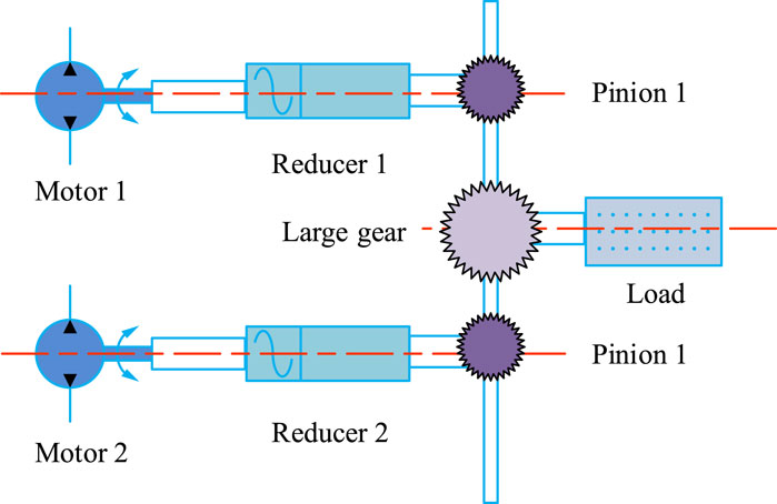
At present, to achieve more efficient and precise automation control, it is necessary to propose a strategy and method for collaborative control of two motors, namely, dual-MCA (Kuznetsov et al., 2024). However, the construction of dual-MCA is a complex process that involves multiple aspects such as the establishment of motor models, selection of control strategies, implementation of algorithms, and system debugging (Liu and Zhao, 2022; Xue et al., 2024). This study explores the selection of algorithms and control strategies. The dual motor system is shown in Figure 1.
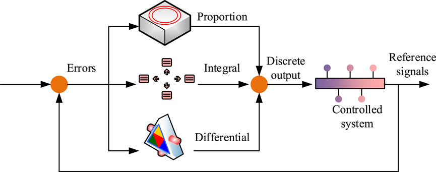
In Figure 1, the dual motor control system consists of paired motors, reducers, small gears, a large gear, and a load. It adopts a torque curve design to apply compensating torque to two motors. During system startup or steering, one motor is responsible for outputting driving torque while the other provides braking torque. Upon a change in direction of motion, the motor that is previously responsible for providing braking torque is converted to output driving torque, and vice versa. This ensures that there is always a corresponding gear that maintains effective transmission engagement with another gear. As the system completes startup and steering, and the load torque increases, the system will gradually reduce the compensation torque, allowing the two motors to work together and share the drive of the load. Considering the three loop control of position, speed, and current in a dual motor system, this study uses DMBC to apply bias torque to the motor to achieve linear control of torque and analyzes MCA. At present, the excellent modern intelligent MCA mainly includes PID algorithm, Active Disturbance Rejection Control (ADRC) algorithm, Fuzzy Control (FC) algorithm, Sliding Mode Control (SMC) algorithm, and GA (Pandi and Arockia, 2023). The PID control algorithm is a data-driven method that adjusts the error between the measured value and the set value of the controlled object to achieve stable and accurate control. It plays a key role in motor automation control systems (Cui et al., 2024). The structural diagram of AECS controlled by PID algorithm is shown in Figure 2.
In Figure 2, the PID algorithm mainly consists of 3 parts, namely, the proportional part, the integral part, and the derivative part. The output of the proportional part is proportional to the error signal, where the larger the proportional gain, the more sensitive the controller is to the error response. The integral part is responsible for accumulating and summing the error signals over time to eliminate steady-state errors and improve system stability. The differential part is responsible for measuring the rate of change of the error signal, predicting the future trend of the error, and providing advanced control. Finally, by calculating the weighted sum of these three parts to adjust the control input, the output of AECS can be closer to or reach the desired set point. The calculation formula for error value
In Equation 1,
In Equation 2,
In Equation 3, the algebraic meaning remains the same as before. The calculation of the controller input increment
In Equation 4,
In Figure 3, the MFAC algorithm is an accurate mathematical model that does not depend on the controlled object, including neural network structures such as multi-layer perceptrons, which can be used to update controller parameters online and adapt to dynamic changes in the system (Qi et al., 2021). It mainly consists of three parts, namely, the controller, the controlled system, and parameter identification. The controller is the core part of the model free adaptive control algorithm, which can calculate control actions based on system inputs and outputs without the need to model the controlled system. The output of the controller will directly affect the behavior of the controlled system. Parameter identification is responsible for obtaining the parameters of the system model. MFAC achieves effective control of complex systems through this structural framework, without relying on precise system models, making it particularly suitable for AECS systems that are difficult to model or have frequent model changes. The expression of discrete-time nonlinear
In Equation 5,
In Equation 6,
In Equation 7,
2.2 Construction of ECA model based on dual-MCA
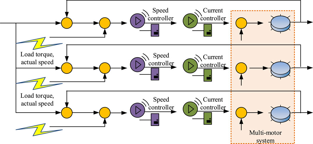
Although the DMBC-MFAC-PID algorithm exhibits good dynamic response and anti-interference ability during the start-up phase and steady-state of the control system under load disturbances, it still cannot meet the requirements of dual motor cooperative control AECS. There are mainly two ways of coordination between motors in dual motor AECS, namely, electrical coupling and mechanical coupling. Among them, the electric coupling method can avoid the defect of certain degree of wear and tear caused by long-term use of connecting components. The most commonly used control structure in electrical coupling is RCCS (Saminu et al., 2023), as shown in Figure 4.
In Figure 4, RCCS mainly improves the collaborative effect of AECS system by introducing speed compensator. The output of this compensator is not single, but is finely calculated by the SCE between the motors. The SCEs of each motor are weighted by their respective coupling coefficients and then comprehensively accumulated. This not only considers the mutual influence between the motors but also dynamically adjusts the coupling coefficient to enable AECS to respond more flexibly to various operating conditions, thereby significantly improving the overall dynamic response and stability. Through this intelligent compensation mechanism, RCCS can achieve more efficient and accurate multi-motor coordinated control. The output
In Equation 8,
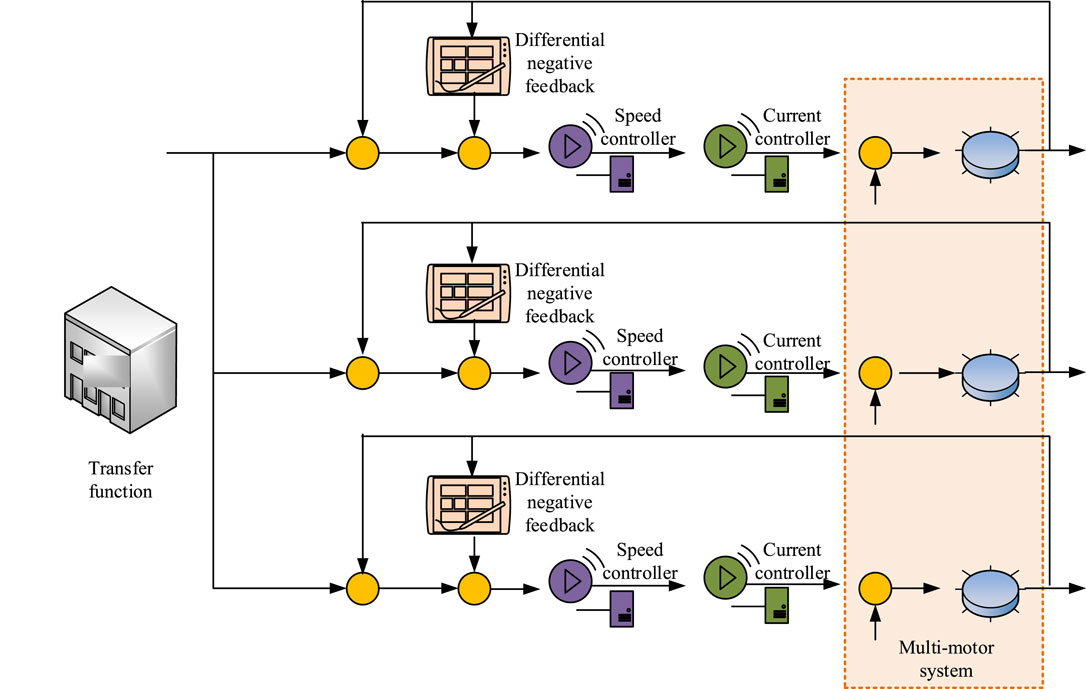
In Figure 5, IRCCS mainly consists of four parts: DNF, speed controller, current controller, and multi-motor system. IRCCS simplifies the speed compensator to a certain extent. The speed compensator only includes the speed difference between the motor’s own speed and the average speed of multiple motors. Each motor’s current loop controller input also includes a compensation variable to control the collaborative performance of the system. DNF suppresses overshoot and reduces SCE. The output formula of the speed compensator for the motor is shown in Equation 9.
In Equation 9,
In Equation 10,
In Equation 11,
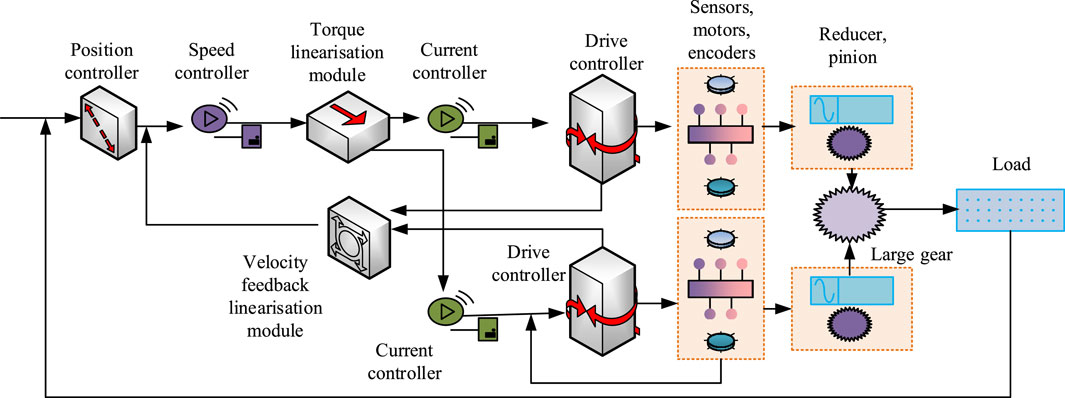
In Figure 6, the Final model based on dual-MCA mainly consists of a position controller, a speed controller, a torque linearization module, a speed feedback linearization module, a current controller, a drive controller, sensors, and loads. It also includes components such as actuators, feedback devices, and mechanical transmissions. This study designs a torque linearization module to achieve torque linearization control and simplify the implementation of the DMBC-MFAC-PID algorithm. The position controller and speed controller are responsible for real-time monitoring of the status of the dual motor system, as well as the inputting of the collected position and speed information as feedback signals to the controller. The controller generates control instructions based on feedback signals and predetermined control strategies. The actuator receives instructions from the controller and converts them into mechanical motion. The Final model can achieve precise control of the load through precise sensor feedback and advanced control strategies.
3 Results
To verify the performance of DMBC-MFAC-PID dual-MCA and Final model, this study first built a suitable servo control system and preprocessed the test data, using a portion of the data for algorithm training. Secondly, performance and simulation experiments were conducted on the DMBC-MFAC-PID algorithm and the Final model to verify the actual effectiveness of the ECA model.
3.1 Performance testing of DMBC-MFAC-PID dual-MCA
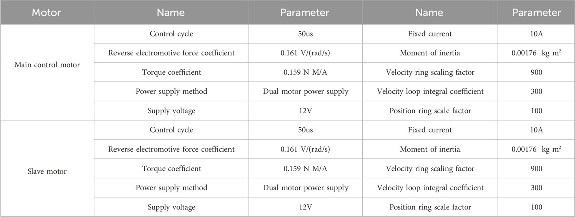
This study takes the 32-bit integer angle value of each rotation cycle as input. The actual 32-bit integer mechanical angle value of the motor is fed back through the encoder and differentiated as the feedback value. The Simulink dataset is used as the testing data source and is divided into training and testing sets in an 8:2 ratio. Table 1 shows the basic parameter configurations of two motors.
Based on Table 1, after normalizing and cleaning the data in Simulink, this study conducts ablation tests on DMBC-MFAC-PID dual-MCA using random sampling and accuracy as the indicator, as shown in Figure 7.
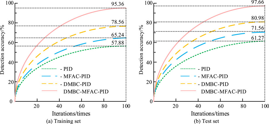
Figure 7. Ablation test results of DMBC-MFAC-PID control algorithm for each module. (A) Training set. (B) Test set.
In the training set of Figure 7, the accuracy of the four algorithms -PID, -MFAC-PID, -DMBC-PID, and -DMBC-MFAC-PID is 57.88%, 65.24%, 78.56%, and 95.36%, respectively. Due to the relatively small proportion of sample data in the test set, the accuracy of the four algorithms is relatively high, at 61.27%, 71.56%, 80.98%, and 97.66%, respectively. Therefore, the DMBC, MFAC, and PID modules all have a positive promoting effect on the final DMBC-MFAC-PID algorithm. The DMBC module significantly enhances the algorithm’s ability to adapt to changes in the system dynamics by providing finer information about the dynamics of the model. The MFAC module improves the control accuracy by optimizing the control signals. The PID module achieves effective reduction of the system error by adjusting the proportional, integral, and differential control parameters to achieve an effective reduction of the system error. The combined effect of these modules results in the DMBC-MFAC-PID algorithm demonstrating superior performance on both the training and test sets, thereby substantiating the algorithm’s efficacy in enhancing control precision and adapting to intricate dynamic environments. Secondly, this study introduces Direct Torque Control (DTC) algorithm, Field Oriented Control (FOC) algorithm, and Iterative Learning Control (ILC) algorithm as comparisons, and conducts performance tests using position deviation as the indicator. Figure 8 shows the specific results.
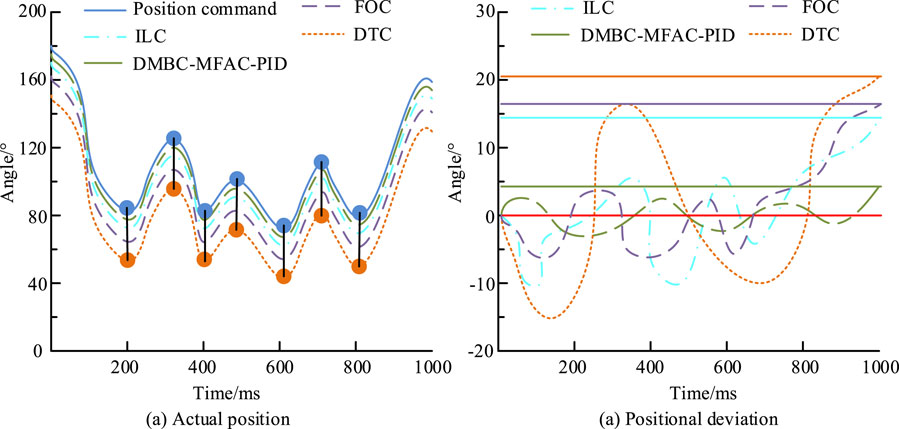
Figure 8. Curves of actual position and position deviation over time for four algorithms. (A) Actual position. (B) Positional deviation.
Figures 8A, B show the curves of actual position and position deviation over time for four algorithms under position instructions. The actual position curve will change with the variation of the position command curve, and there is a certain delay time between the actual position curve and the position command curve. The position deviation values of DTC, FOC, ILC, and DMBC-MFAC-PID throughout the entire process are within the range of ±21°, ±18°, ±15°, and ±5°, with maximum tracking errors of 20.16°, 17.68°, 14.55°, and 4.91°. The DTC algorithm is simple and intuitive, but its fluctuations in torque and flux control can lead to unstable performance. Although the FOC algorithm demonstrates efficacy in motor control, its functionality is contingent upon precise motor parameters, and its implementation is relatively intricate. The ILC algorithm performs well in repetitive tasks, but may require more iterations to achieve the expected control results when facing nonlinear time-varying systems. These factors together result in the DTC, FOC, and ILC algorithms not performing as well as the DMBC-MFAC-PID dual-MCA. This indicates that the proposed DMBC-MFAC-PID dual-MCA can have more precise application effects and less error impact. By combining the advantages of multiple control strategies, it is possible to achieve precise control of the electromechanical control system, especially in reducing the tracking error and improving the stability of the system. To more accurately quantify the performance comparison results of various ECAs, this study continues to use precision (P), recall (R), F1 value, and running time as reference indicators to conduct multi index testing on the above ECAs, as listed in Table 2.
In Table 2, DMBC-MFAC-PID has good accuracy and comprehensive quality. Its running time on the training and testing sets is 2.12 min and 2.01 s, with P, R, and F1 values of 93.58%, 92.57%, 93.27%, and 96.57%, 95.24%, and 95.66%, respectively. In both datasets, DMBC-MFAC-PID has the optimal values, demonstrating its excellent performance on ECA.
3.2 Simulation testing of the final model
This study establishes a dual motor testing platform to conduct simulation testing of ECA models. When verifying the rigidity of a single motor, it is needed to keep the basic control parameters of the motor unchanged. During the dual motor rigidity verification, the main control motor sends the 32-bit angle values from the encoder in real-time to the upper computer. A 0.5 kg weight and a 100 mm aluminum rod are used to simulate the torque application method at the outer end of the control motor shaft. In addition, this study also introduces popular ECA models, namely, Direct Current Torque Motor Control (DCTMC), Decoupling Control Structure (DCS), Error Coupling Control Structure (ECCS), and compares them with the Final model. The speed output curves of the four models during no-load start-up are displayed in Figure 9.
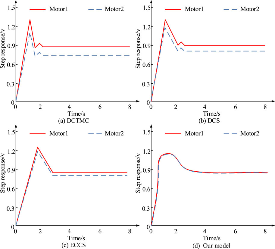
Figure 9. Speed output graphs of the four models at no-load startup. (A) DCTMC. (B) DCS. (C) ECCS. (D) Our model.
Figures 9A–D show the speed output curves of DCTMC, DCS, ECCS, and Final models during no-load start-up. Figure 9 shows that during the no-load start-up phase, DCTMC, DCS, ECCS, and Final model show a significant decrease in maximum tracking error and SCE speed with similar speed. The maximum SCE between the two motors is only 0.02%. The above data indicate that the Final model has excellent synchronization and anti-interference performance. Figure 10 shows the speed output curves of four models under steady-state sudden load.
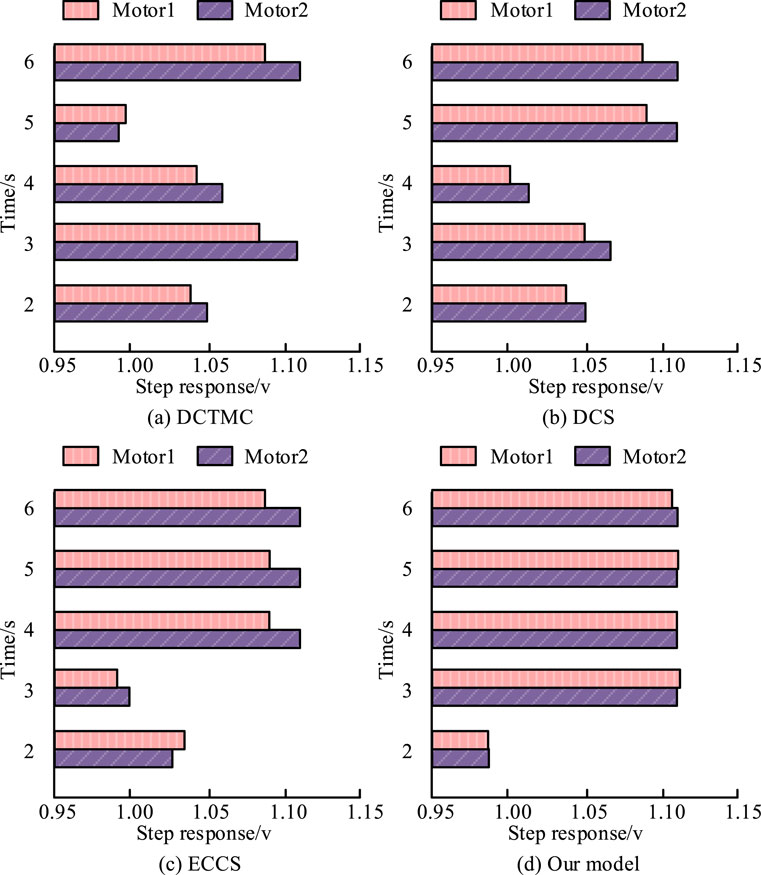
Figure 10. Speed output graphs of the four models at steady state sudden loading. (A) DCTMC. (B) DCS. (C) ECCS. (D) Our model.
Figures 10A–D show the speed output curves of DCTMC, DCS, ECCS, and Final models under steady-state sudden load. Figure 10 shows that the Final model performs the best, followed by the ECCS and DCS models, with DCTMC performing the worst. DCTMC, DCS, ECCS, and Final model reach stable states at 5 s, 4 s, 3 s, and 2 s, respectively. The maximum SCE of the Final model is only 0.3%. This indicates that even under steady-state sudden load conditions, the Final model can have the minimum SCE and the shortest dynamic recovery time, while also having the best anti-interference performance. To better describe the superiority of the proposed method, the study also compares the proposed method with the rest of the published literature. The test results are shown in Table 3.
As shown in Table 3, at the 100rad reference position, the response time and tracking error of Fuzzy-PID, GWO-PID, CNN-PID, and the research method are 1.70 s, 1.50 s, 1.30 s, and 1.20 s, respectively. The tracking error is 0.300rad, 0.243rad, 0.210rad, and 0.005rad, respectively. At the 10rad reference position, the response time and tracking error of Fuzzy-PID are 0.42 s and −0.080rad. The response time and tracking error of GWO-PID are 0.390 s and −0.077rad. The response time and tracking error of CNN-PID are 0.35 s and −0.068rad. The response time and tracking error of the research method are 0.30 s and −0.006rad. The results show that the proposed method can maintain lower tracking error and faster response time in different amplitude of motion control, which is attributed to the better balance of speed and accuracy in the algorithm of the control strategy. Although optimization techniques through control strategies have improved the performance of Fuzzy PID, GWO-PID, and CNN-PID to some extent, they still fall short in terms of comprehensive response speed and tracking accuracy compared to research methods. These results highlight the potential of the research method in improving the performance of electromechanical control systems.
4 Conclusion
In modern industrial automation, precise and efficient motor control is the key to achieving high-performance automation systems. Among them, multi-motor control has become a demand for the development of mechatronics integration at present. Therefore, this study proposed a novel Final model based on DMBC-MFAC-PID dual-MCA. By working together with two motors, it was possible to provide greater torque output and higher dynamic response. The experiment showed that compared with the same type of MCA, the proposed DMBC-MFAC-PID dual-MCA had a position deviation value within ±5°, a maximum tracking error of 4.91°, and an accuracy rate of 97.66%. Its running time on the dataset was 2.01 s, with P, R, and F1 values reaching 96.57%, 95.24%, and 95.66%. Simulation tests have shown that the Final model has excellent synchronization performance and anti-interference ability, both during the no-load start-up phase and under steady-state sudden load conditions. The final model could reach a stable state in 2 s. Overall, the Final model can significantly improve the control accuracy and stability of dual motor control systems, which is of great significance for enhancing the performance of industrial automation equipment. However, due to limited time and incomplete testing platform, this study only conducted preliminary verification of the motor control system and dual MCA. In the future, further optimization of the multi-motor control system can be carried out to achieve comprehensiveness of the research.
Data availability statement
The original contributions presented in the study are included in the article/supplementary material, further inquiries can be directed to the corresponding author.
Author contributions
WL: Conceptualization, Methodology, Validation, Writing–original draft, Writing–review and editing.
Funding
The author declare that no financial support was received for the research, authorship, and/or publication of this article.
Conflict of interest
The author declares that the research was conducted in the absence of any commercial or financial relationships that could be construed as a potential conflict of interest.
Publisher’s note
All claims expressed in this article are solely those of the authors and do not necessarily represent those of their affiliated organizations, or those of the publisher, the editors and the reviewers. Any product that may be evaluated in this article, or claim that may be made by its manufacturer, is not guaranteed or endorsed by the publisher.
References
Chen, J., Lu, Q., Bai, J., Xu, X., Yao, Y., and Fang, W. (2021). A temperature control method for microaccelerometer chips based on genetic algorithm and fuzzy PID control. Micromachines 12 (12), 1511–1523. doi:10.3390/mi12121511
Chen, S. F. (2022). Low-cost and high-efficiency electromechanical integration for smart factories of IoT with CNN and FOPID controller design under the impact of COVID-19. Appl. Sci. 12 (8), 31–39. doi:10.3390/app12073231
Cui, Z., Zuo, H., Qiao, W., Li, H., Du, F., Wang, Y., et al. (2024). Fuzzy Proportional Integral Derivative control of a voice coil actuator system for adaptive deformable mirrors. Astronomical Tech. Instrum. 1 (3), 179–186. doi:10.61977/ati2024025
Kuznetsov, V. E., Lukichev, A. N., Nguyen, D. K., Bogdanova, S. M., and Filatov, D. M. (2024). A synchronization algorithm for the control system of a multichannel electromechanical steering actuator. Russ. Electr. Eng. 95 (3), 208–216. doi:10.3103/s1068371224700172
Li, C., Yi, W., Yin, H., and Guan, J. (2021). Fuzzy pid control of electromechanical actuator system. J. Phys. Conf. Ser. 1721 (1), 012052–12120. doi:10.1088/1742-6596/1721/1/012052
Liu, Y., and Zhao, Y. (2022). Electrical automation control technology of electromechanical equipment based on artificial intelligence technology. J. Phys. Conf. Ser. 2181 (1), 012045–12116. doi:10.1088/1742-6596/2181/1/012045
Pandi, M. M., and Arockia, E. X. S. (2023). BLDC motor torque ripple factor lowering and FOPID based motion control using DGOA algorithm. J. low Freq. noise, Vib. Act. control 42 (4), 1636–1648. doi:10.1177/14613484231181449
Park, H. Y., and Kim, J. H. (2023). Model-free control approach to uncertain Euler-Lagrange equations with a Lyapunov-based $ L_\infty $-gain analysis. AIMS Math. 8 (8), 17666–17686. doi:10.3934/math.2023902
Qi, Y., Zhao, X., and Huang, J. (2021). Data-driven event-triggered control for switched systems based on neural network disturbance compensation. Neurocomputing 490 (11), 370–379. doi:10.1016/j.neucom.2021.11.103
Saminu, S., Xu, G., Zhang, S., Kader, I. A. E., Aliyu, H. A., Jabire, A. H., et al. (2023). Applications of artificial intelligence in automatic detection of epileptic seizures using EEG signals: a review. Artif. Intell. Appl. 1 (1), 11–25. doi:10.47852/bonviewaia2202297
Sarangapani, E., Narmadhai, N., and Santhosh, N. (2021). Industry 4.0 technologies incorporated with delta PLC based smart home automation for rural development. IOP Conf. Ser. Mater. Sci. Eng. 1084 (1), 012112–012128. doi:10.1088/1757-899x/1084/1/012112
Tian, S., and Zhang, J. W. (2023). Design of quadrotor aircraft control system using PID method. J. Phys. Conf. Ser. 2476 (1), 012070–012077. doi:10.1088/1742-6596/2476/1/012070
Varga, B., Tar, J. K., and Horvath, R. (2024). Fractional order inspired iterative adaptive control. Robotica Int. J. Inf. Educ. Res. robotics Artif. Intell. 15 (2), 42–50. doi:10.1017/S0263574723001595
Wang, S., Meng, F., and Yang, Y. (2024b). Research on the cabin pressure control system based on the gray wolf fuzzy PID algorithm. IOP Publ. Ltd. 12 (78), 1742–1750. doi:10.1088/1742-6596/2764/1/012078
Wang, X., Liu, H., Ma, J., Gao, Y., and Wu, Y. (2024a). Compensation-based characteristic modeling and tracking control for electromechanical servo systems with backlash and torque disturbance. Int. J. Control, Automation Syst. 22 (6), 1869–1882. doi:10.1007/s12555-022-0643-1
Xi, Y., and Xing, Q. (2021). Automatic electromechanical control system based on PLC technology. J. Phys. Conf. Ser. 2143 (1), 012037–12117. doi:10.1088/1742-6596/2143/1/012037
Xue, Q., Zhang, X., Chen, H., Yue, M., Teng, T., and Yu, J. (2024). Dynamic coordinated control strategy of a dual-motor hybrid electric vehicle based on clutch friction torque observer. Heliyon 10 (5), e27255–e27262. doi:10.1016/j.heliyon.2024.e27255
Keywords: dual motor, PID, remote control coupling, mechanical and electrical control, self-adaption
Citation: Lu W (2024) Optimization and design of electromechanical control automation based on dual motor control algorithm. Front. Mech. Eng. 10:1485041. doi: 10.3389/fmech.2024.1485041
Received: 23 August 2024; Accepted: 15 November 2024;
Published: 06 December 2024.
Edited by:
Yaoyao Wang, Nanjing University of Aeronautics and Astronautics, ChinaReviewed by:
Jie Fan, Beijing Institute of Technology, ChinaWei Guo, City University of Hong Kong, Hong Kong SAR, China
Copyright © 2024 Lu. This is an open-access article distributed under the terms of the Creative Commons Attribution License (CC BY). The use, distribution or reproduction in other forums is permitted, provided the original author(s) and the copyright owner(s) are credited and that the original publication in this journal is cited, in accordance with accepted academic practice. No use, distribution or reproduction is permitted which does not comply with these terms.
*Correspondence: Wei Lu, dGlhbmJhbzk1MDFAMTYzLmNvbQ==
 Wei Lu