
94% of researchers rate our articles as excellent or good
Learn more about the work of our research integrity team to safeguard the quality of each article we publish.
Find out more
ORIGINAL RESEARCH article
Front. Mech. Eng., 20 September 2024
Sec. Tribology
Volume 10 - 2024 | https://doi.org/10.3389/fmech.2024.1470312
This article is part of the Research TopicVisualization Techniques in TribologyView all 17 articles
 Takayuki Tokoroyama1*
 Masahiro Okashita1
 Ruixi Zhang1Motoyuki Murashima2
 Ryo Tsuboi3Takuji Yoshida3
 Hiroshi Shiomi4Noritsugu Umehara1
When the lubricating oil flowing between the contact surfaces contains simulated wear particles, it is considered that there is a high possibility for the particles to enter between the contact surfaces if the particles are present on the disk side in a friction test between a fixed ball and a rotating disk. For particles with a diameter of 0.8 μm, it has been previously shown that the entrainment frequency changes with the outside oil film thickness, but the effect of the disk material on the amount of particle deposition and the visualization of particle movement direction due to vortices generated between the contact surfaces had not been performed. In this study, by using SiO2 disks and sapphire disks with different Hamaker constants, the effect on the amount of particle deposition in front of the contact surfaces was experimentally clarified by changing the van der Waals forces acting between the particles and the disks. Additionally, assuming that vortices generated in the oil film between the contact surfaces move the particles to the disk surface side, the flow direction of the lubricating oil was visualized using Navier-Stokes simulation.
It is not difficult to imagine that abrasive wear particles entraining the contact surfaces and causing abrasive wear can drastically reduce the lifespan of sliding materials. For example, in the wear of the cylinder liner in an automobile engine, material transfer occurs from the aluminum-silicon alloy to the cast iron side. This wear debris gets embedded into the cylinder liner (Milojević et al., 2023; Milojević et al., 2024; Gajevic et al., 2024; Milojević and Stojanović, 2018). When using hard carbon-based thin coatings in lubricating oil (Abdollah et al., 2012; Abdollah et al., 2010), delamination from the substrate (Lee et al., 2019; Lee et al., 2020) and entrainment into the contact surfaces is a significant issue that drastically reduces the material’s lifespan (Lee et al., 2018; Kassim et al., 2020; Kassim et al., 2021). The entrainment of particles between contact surfaces depends on the size of the particles, the hardness and material of the contact surfaces, the viscosity and temperature of the lubricating oil or grease, the contact form, and the sliding speed. Dwyer-Joyce et al. have continued to address this issue, reporting that particles drawn into the contact surfaces scratch the surface and are expelled as wear debris. They explain that particles in the approaching oil layer, where the lubricant oil thickness is about the same as the particle diameter, are drawn into the contact surfaces (Dwyer-Joyce, 1999; Nilsson et al., 2006). Strubel et al. have also continued simulations and experiments on the influx of lubricating oil between contact surfaces (Strubel et al., 2016; Strubel et al., 2017a; Strubel et al., 2017b). Observing the movement of particles within sub-millimeter-sized channels and small pores are challenging, and the use of techniques such as surface-enhanced Raman spectroscopy (SERS) has been considered to enhance particle visibility (Chang et al., 2017; Chang et al., 2019), Quantum Dots method (Azuma et al., 2023), Optical reflectance spectroscopic in situ observation to realize the real-time generation of tribofilm (Hashizume et al., 2021), and traditional observation of the surface by optical microscope or SEM (scanning electron microscope) (Aboua et al., 2018a; Aboua et al., 2019; Aboua et al., 2018b). Further developments in this area are anticipated. For particles in the lubricating oil to be drawn into the contact surfaces, they need to be near the solid wall moving towards the contact surface, where an inflow exists. However, when the amount of lubricating oil is high, most particles are eliminated by the reverse flow generated in front of the contact surface. For instance, to improve fuel efficiency in automobiles by reducing the amount of lubricating oil supplied to the bearings or to meet the reduction in oil pumps, it is essential to clarify how particle entrainment into the contact surfaces occurs when the amount of lubricating oil is low. In recent years, it has been reported that mixing carbon nanotubes and nanoparticles into lubricating oil can improve tribological properties (Bukvić et al., 2024). The authors have previously clarified how particles infiltrate the contact surfaces in environments with insufficient lubricating oil (Tokoroyama et al., 2024). They reported that the frequency of particle entrainment changes based on the ratio of the oil film thickness outside the contact point (hereafter referred to as outside oil film thickness Hi) to the particle diameter r. Particularly, it has been clarified that the number of entrainment particles increases in the range of 1 ≤ r ≤ 2, although the mechanism is not yet clear. It is hypothesized that the entrainment frequency increases when particles can stay near the solid wall. Therefore, it is expected that the number of entrainment particles will vary depending on the material of the solid wall. Indeed, the hydrophilicity and lipophilicity of the particles are also considered to be related to their penetration (Ghosh and Böker, 2019), and this is an issue that should be addressed in the future.
In the study by Nikas (2007), Nikas (2020), it was predicted that when the particle size is less than 1 μm, the van der Waals forces on the disk surface become a significant source of force for particle penetration, but this had not been demonstrated. It is important that we should experimentally prove this prediction to be correct. Additionally, in a previous author’s paper (Tokoroyama et al., 2024), it was speculated that a reverse flow vortex component forms in the direction away from the disk surface in front of the contact point, but this was only a hypothesis. Therefore, using Navier-Stokes numerical simulations to verify the presence of a vortex exists at a specific location where particles are lifted off the disk surface.
In this study, we investigate the relationship between the amount of particle deposition in front of the contact surfaces and the number of entrainment particles using an in situ observation method with fluorescent stained particles, which allows for observation of even microscopic particles that are unobservable due to optical limitations when using an optical microscope of around 1 μm, 0.8 μm is considered the largest particle that can enter between contact surfaces and promote wear while being below the optical limit, making the observation of particles of this size the most important. Transparent materials such as quartz and sapphire were used for the solid wall to enable observation of the contact surfaces. For the friction test conditions, a transparent disk-shaped test piece and a bearing steel ball were used between the two contact surfaces, under elastic contact conditions and boundary lubrication conditions.
Additionally, the particle deposition observed in the aforementioned experiment is considered to be caused by the flow near the disk within the working fluid. Since the presence of vortices that detach particles from the disk surface is deemed most important, Navier-Stokes numerical simulations under poor lubrication conditions were conducted to clarify the positional relationship between the vortices generated within the thin lubrication film and the contact points.
While reducing the supply of lubricating oil in future automotive development is essential for improving fuel efficiency, ensuring a comfortable cabin environment, and reducing lubricating oil consumption, excessive wear on contact surfaces caused by wear particles in thin lubrication environments must be controlled. From this perspective, it is necessary to understand the tribology of particles of practical around μm sizes and their entry into thin lubrication environments that may occur in the future.
The detail of staining technique and observation equipment were reported in reference Tokoroyama et al. (2024), the brief and important procedure of staining the silica particles is summarized below. The fluorescent staining of silica particles was accomplished using a combination of a silane coupling agent (KBM-4803 from Shin-Etsu Silicone, Japan) and Rhodamine B (from Fujifilm Wako Pure Chemical Corporation, Japan). These silica particles came in three sizes, with average diameters of 0.8, 1.0, and 3.0 μm (supplied by Potters Ballotine Co., Ltd., Japan).
Friction tests were carried out using an in situ observation system called “iFLAT” (Intelligent Fluorescent Light Assisted Tribometer, which equipment can be allowed to use 1.0 N as limitation of normal load, 5.0 mm/s as maximum of sliding speed, and 2,000 fps as frame rate). A schematic of this system is depicted in Figure 1A, with an enlarged view of the observation area shown in Figure 1B. The iFLAT system is equipped with a 532 nm laser source (GLK32200, LASOS, Germany). This laser travels through a light guide from the source, enters an objective lens of an optical microscope, and is directed to the friction area via a sapphire and a quartz disk (1.0 mm thickness, 50 mm diameter, with a surface roughness of approximately 2.0 nmRa, respectively). These transparent materials are used for the visualization of the in situ observation of the surface, and their surface roughness is smaller than that of actual sliding surfaces (such as honing or coating surfaces). However, by changing the surface roughness of the counterpart material’s ball, it will be necessary in the future to clarify the relationship between roughness and particle entry. A fixed SUJ2 bearing ball (approximately 8.0 mm in diameter, with a surface roughness of approximately 7.0 nmRa, it is same property of AISI53200 stainless steel) within a ball holder is placed on a friction cantilever. A dead weight is used to apply a normal load of 0.2 N. The bearing ball reflects the incident laser, and the fluorescently stained particles emit fluorescent light. Both sets of light pass through the sapphire disk before reaching a half-mirror. Subsequently, both lights are directed to a WIG filter, which is a long-pass filter with a cutoff wavelength at 580 nm, effectively eliminating reflected laser light. Finally, the fluorescent light is captured by a CMOS camera, operating at a frame rate of 500 frames per second (fps). The in situ observations were conducted multiple times, and we selected 60 frames (0.12 s) that recorded the highest particle counts within the observation area during the observations. The summary of those conditions are listed in Table 1.
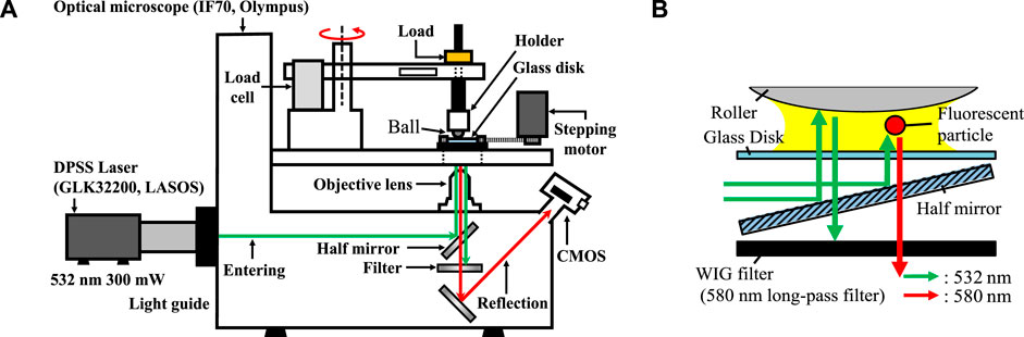
Figure 1. (A) Schematic of iFlat equipment, (B) schematic of inlet laser path through the glass disk to the contact point, and the reflection path through WIG filter.
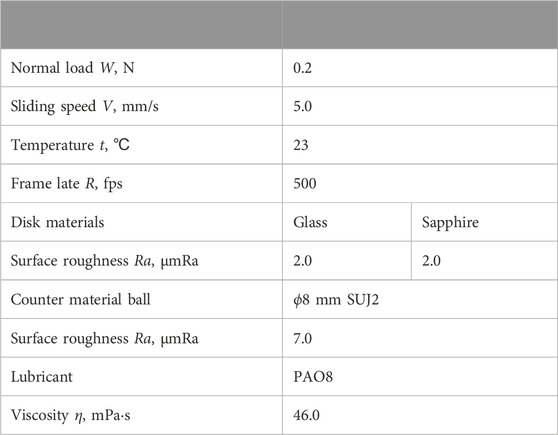
Table 1. Friction test conditions.
The friction test involved the interaction between an SUJ2 ball and a sapphire or a quartz disk lubricated with PAO8 lubricant, which possesses a viscosity of 46.0 mPs s at 40°C. The i-FLAT system was utilized for this test. In the previous report (Tokoroyama et al., 2024), an outside oil film (Hi) was formed by applying a load to the lubricating oil placed between two disks and sliding the two disks to achieve a film of a certain thickness. However, there were issues with the controllability and reproducibility of the oil film thickness. Therefore, a uniform oil film was formed using a spin coater (ACT-220AII). When using a spin coater, the theoretical oil film thickness is calculated by the following Equation 1 (Alfred et al., 1958):
here, h is the oil film thickness, h0 is the initial film thickness, ω is the rotational speed, t is the rotational time, and ν is the kinematic viscosity (Emslie et al., 1958). An oil film was formed using PAO8 at different rotational speeds and times, and the oil film thickness was measured using a reflection spectroscopic film thickness meter. The results are shown in Figure 2. The calibration curve was created using a power approximation so that it would be a function of time t in the theoretical formula, and the power values of t ranged from −0.427 to −0.567, which were close to the theoretical value of −0.5. The experimental Equations 2–4 obtained from the experiment is shown below.
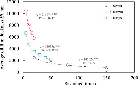
Figure 2. Oil film thickness formed at different rotational speeds and times.
The sapphire disk with the lubricant was secured onto the disk holder, with the ball specimen attached to it. A dead weight of 0.2 N was added to the ball specimen. Fluorescently stained particles, comprising a colloidal liquid of ethanol with a volume of 0.1 μL (assuming that the stained particles are Uniformly dispersed in the solvent, the number of particles contained in 0.1 μL is 20,000 when the diameter is 0.8 μm), were applied onto the oil film, positioned at the same radius as the friction test rotation, just ahead of the contact point. Prior to commencing the in situ friction test, several minutes were allowed to pass to account for ethanol vaporization. The sliding speed was set at 5.0 mm/s (with a rotation radius of approximately 5.0 mm), and the camera operated at a speed of 500 frames per second (fps). We captured a continuous sequence of 60 frames (0.12 s) to tally the number of particles when the highest concentration of particles was observed near the contact point. The sliding distance covered in these 60 frames was approximately 0.6 mm.
A friction test was conducted for 5 s until the fluorescent-stained particles were trapped between the contact surfaces, and the area of deposited particles was measured. Since the particles present on the area emit light due to Rhodamine B, the observed images were converted into 256-level grayscale images, and binarization was performed to calculate the area. A threshold value of 60 was used in this process. The projected area created by particles with a diameter of 0.8 μm on the observation area was approximately 0.5 mm2, and even with adjustments of ±2 levels around 60, the particle area fluctuation was less than 1 mm2, so this value was adopted.
To identify the position where the lubricant generates vortices that cause particles to detach from the disk surface, the flow generated within the thin lubricant film was visualized using Navier-Stokes method simulations. Quartz was used as the disk material, and PAO8 was used as the lubricant. The contact angle between the lubricant and the quartz was set to 11° (the value measured using a contact angle meter). The movement speed of the disk was 5 mm/s, the same as in the experiment, and in the simulation, the lubricant and other test specimens were set to room temperature (23°C).
In the Navier-Stokes simulation (simulations were performed using Ansys Fluent 2020 R1 (ANSYS, Inc., US).), a contact region as shown in Figure 3 was prepared. The outside oil film thickness was set to values (Hi = 0.4 as half of particles, 1.2 as three times thicker than 0.4 μm and it is within the value of 1 ≤ r ≤ 2, and 2.0 μm as five times thicker than 0.4 μm and it is the value of r > 2). In the figure, i) represents the Hertz contact circle generated between the contacting ball and disk, ii) is a cross-section divided at the center of the Hertz contact circle by the incoming lubricating oil, assuming that the flow occurring in the oil film is symmetrically present. The cross-section of the incoming lubricating oil is represented by iii), and iv) is assumed to symmetrically exist as a pressure outlet. The interface between air and oil was defined as VOF (volume of fluid) = 0.5, assuming that each medium exists in equal amounts.
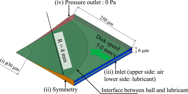
Figure 3. Schematic of N-S simulation area.
To clarify the effect of outside oil film thickness on the number of particles entering between contact surfaces, friction tests were conducted using glass particles with a diameter of approximately 0.8 μm and employing sapphire disks and quartz disks as counter materials. Figure 4 shows the results of experiments conducted under dry conditions after the solvent dropped before the observation area had dried. The areas covered by particles deposited on the surface of the sapphire disk (Figure 4A) and the quartz disk (Figure 4B) were almost the same, and the numerical results of the areas (Figure 4C) also yielded nearly identical values. The results for when the outside oil film thickness was set to 0.8 μm are shown in Figure 5. It is evident that the number of particles deposited is higher on the sapphire disk and very low on the quartz disk. Next, the results for when the outside oil film thickness was set to 1.4 μm are shown in Figure 6. There was a tendency for the number of particles deposited on the quartz disk to increase compared to the 0.8 μm case. Finally, the results for when the outside oil film thickness was set to 5.0 μm are shown in Figure 7. The number of particles deposited decreased on both the sapphire and quartz surfaces. The relationship between the measured number of particles and the outside oil film thickness is shown in Figure 8. For both the sapphire disk and the quartz disk, the number of deposited particles was the same under conditions without lubricating oil, and the number of particles decreased as the outside oil film thickness increased. However, the number of particles deposited on the quartz disk was consistently lower than on the sapphire disk. From these results, it is shown that the number of deposited particles varies depending on the disk material.
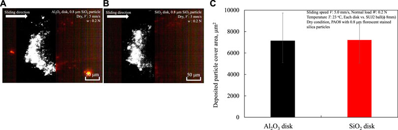
Figure 4. Deposition results of 0.8 μm diameter particles between contact surfaces under conditions without lubricant: (A) sapphire disk, (B) quartz disk, (C) particle area deposited on the surface of each disk specimen.
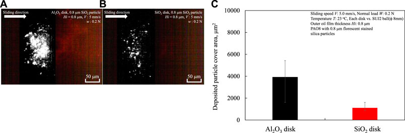
Figure 5. Deposition results of 0.8 μm diameter particles between contact surfaces under conditions with lubricant which outside oil film thickness was approximately 0.8 μm: (A) sapphire disk, (B) quartz disk, (C) particle area deposited on the surface of each disk specimen.
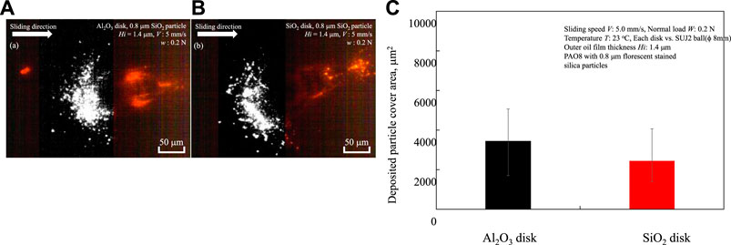
Figure 6. Deposition results of 0.8 μm diameter particles between contact surfaces under conditions with lubricant which outside oil film thickness was approximately 1.4 μm: (A) sapphire disk, (B) quartz disk, (C) particle area deposited on the surface of each disk specimen.
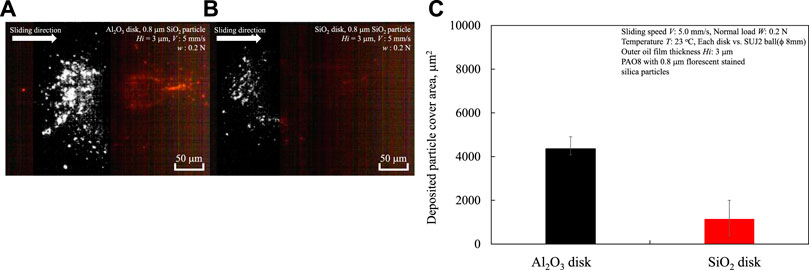
Figure 7. Deposition results of 0.8 μm diameter particles between contact surfaces under conditions with lubricant which outside oil film thickness was approximately 5.0 μm: (A) sapphire disk, (B) quartz disk, (C) particle area deposited on the surface of each disk specimen.
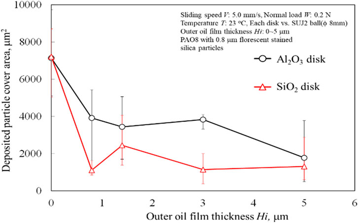
Figure 8. The effect of outside oil film thickness on particle deposition area.
It is believed that the flow field generated near the contact point affects the particle’s movement speed and retention near the contact point. Since the retention time is considered to be influenced by the rotation speed of the disk specimen, experiments were conducted by reducing the sliding speed from 5 mm/s used in the previous tests to 0.5 mm/s. Additionally, to clarify the effect of normal load acting between the two contact surfaces on the number of particle deposits, experiments were conducted by increasing the normal load to 1.0 N. The results are shown in Figures 9, 10, respectively.
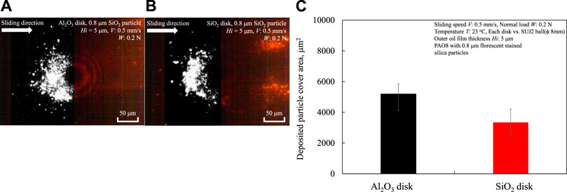
Figure 9. Deposition results of 0.8 μm diameter particles between contact surfaces under conditions with lubricant which outside oil film thickness was approximately 5.0 μm using 0.5 mm/s of disk speed: (A) sapphire disk, (B) quartz disk, (C) particle area deposited on the surface of each disk specimen.
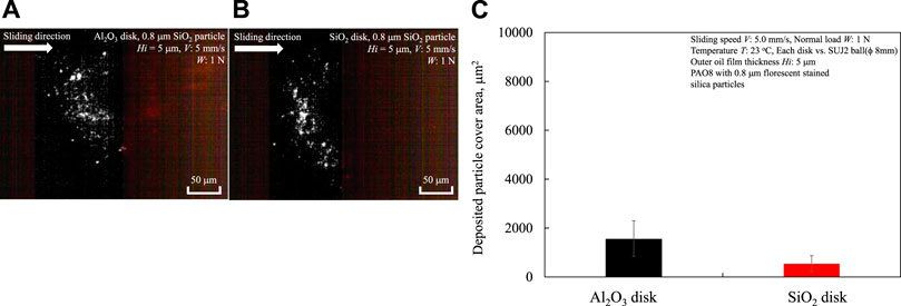
Figure 10. Deposition results of 0.8 μm diameter particles between contact surfaces under conditions with lubricant which outside oil film thickness was approximately 5.0 μm using 1.0 N of normal load: (A) sapphire disk, (B) quartz disk, (C) particle area deposited on the surface of each disk specimen.
By reducing the rotation speed of the disk from 5.0 mm/s to 0.5 mm/s, the number of particles deposited between the contact surfaces increased significantly compared to Figure 6. Approximately twice as many particles were deposited on the sapphire disk, and about 1.5 times as many particles were deposited on the quartz disk. From these results, it can be concluded that the flow generated near the contact surface affects particle deposition.
Next, Figure 10 shows the observation results when the normal load was increased from 0.2 N to 1.0 N under a sliding speed of 5.0 mm/s and an outside oil film thickness of 5.0 μm. Compared to Figure 7, where a similar experiment was conducted at 0.2 N, there are almost small number of particles present between the contact surfaces, similar to the results shown in Figure 7. From these results, it can be concluded that under boundary lubrication conditions, the normal load applied between the contact surfaces does not affect the number of particles entering.
As previously mentioned, it is evident that the number of particles deposited near the contact point varies depending on the material of the disk specimens used and the small outside oil film thickness, using particles with a diameter of 0.8 μm. The different amounts of particle deposition may be due to the inherent physical properties of the disk materials (e.g., van der Waals forces or wettability).
However, it is not clear to what extent these physical properties affect the flow near the contact point. Therefore, particles with a diameter of 0.02 μm were used to observe the flow on the surfaces of sapphire and quartz disks. The results are shown in Figure 11. The yellow circles in the figure indicate positions where the geometric gap between the SUJ2 ball and the disk surface is 0.8 μm. Calculating the particle movement speed on each disk surface from the subtraction between frames, the speed was approximately 5.0 mm/s, which is similar to the disk speed in the sliding direction, indicating that the flow speed is almost the same regardless of the disk material.
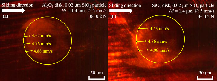
Figure 11. The effect of disk material on the flow near the contact point with an outside oil film thickness of 1.4 μm by using 0.02 μm diameter SiO2 particles: (A) sapphire, (B) quartz.
The flow near the contact point is unaffected by the disk material, but the amount of particle deposition near the contact point shows the influence of the disk material. Therefore, it is inferred that van der Waals forces, as inherent material properties, play a role (Regarding wettability mentioned earlier, the contact angles of quartz and sapphire with PAO8 are both approximately 11°, showing no difference, thus having no effect.) Nikas et al. has demonstrated through numerical analysis that frictional forces significantly contribute to the trapping of particles between two sliding surfaces, and that for very small particles below 5 μm, the influence of van der Waals forces on particle behavior becomes comparable to fluid forces (Nikas, 2007; Nikas, 2020). Therefore, assuming forces other than the fluid pushing against the deposited particles, Figure 12 shows the geometrical model of the forces acting on a particle when it is trapped. T is the frictional force, N is the normal force, F is the fluid force, G is the van der Waals force acting between the disk and the particle, and θ is the angle at which the disk and the particle contact at a geometric gap of 0.8 μm. To investigate the change in the number of particles deposited by the disk, the van der Waals force represented by G is assumed to only affect when the distance between the particle and the disk is very close, and it is assumed to act only between the disk and the particle. Under these conditions, it is considered that the particle will be trapped when the sum of the frictional forces T1 and T2 is greater than the reverse fluid force F. When a particle is trapped between the sphere and the disk, it is considered that the particle will move into the contact area when the total frictional force of the particles deposited near the contact surface exceeds the horizontally decomposed force of the load.
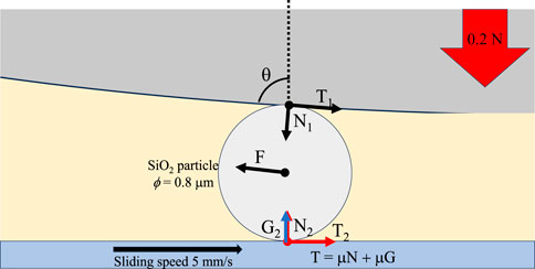
Figure 12. The schematics of several force generating to the particle between two surfaces.
Here, we use the following Equations 5–7 described in the report by Nikas et al.,
Fx is the fluid force in the sliding direction generated near the contact area, η0 is the viscosity of the lubricating oil, u1 and u2 are the velocities of the sliding surfaces, hc is the minimum gap at the contact area, d is the particle diameter, G is the van der Waals force acting between the particle and the disk, H is the Hamaker constant, and s is the minimum distance between the particle and the disk, and σ is the surface roughness. The hd, hf, and hp are Hamaker constant of each element as disk, fluid, and particle. To calculate the forces acting on the particles, we substituted the values shown in Table 2 for the Hamaker constant, lubricating oil viscosity, and other parameters of the test specimens used in the experiment. As a result, the forces Fx and G moving the particles within the contact surface were Fx = 0.64 nN, Gsapphire = 0.18 nN, and Gquarts = 0.077 nN, respectively. These results indicate that sapphire disk has higher affection for particles and the force is also same order of fluid force.
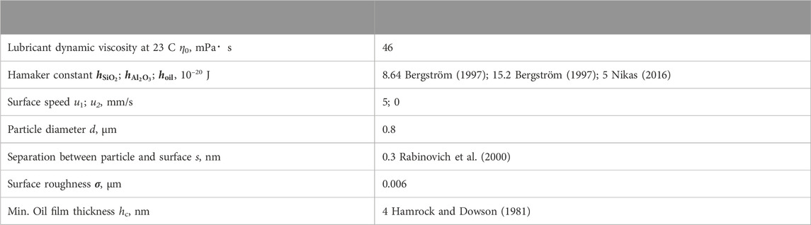
Table 2. The physical properties of lubricant, particles and disk specimen.
The flow direction of lubricating oil containing particles at different outside oil film thicknesses was calculated. The results of averaging the velocity vectors in the vertical direction (defined as the y-axis) within the contact surface, accompanying the entry of lubricating oil into the contact surface at an outside oil film thickness Hi = 0.4 μm, are shown in Figure 13A. An air-liquid interface is formed between the two surfaces in contact at a position approximately 95 μm (x = 95 μm) from the centre of the Hertz contact. Assuming that the likelihood of particle entry increases when particles move towards the disc side due to downward flow in the y-axis direction, the flow is strongest downwards around x = 93 μm. However, as will be discussed later, since the geometric distance between the contacting surfaces equals the particle diameter of 0.8 μm at x = 160 μm, in the case of Hi = 0.4 μm, particles with a diameter of 0.8 μm first contact the surface of the SUJ2 ball. Despite the presence of lubricating oil, particles on the disc are assumed to contact the SUJ2 ball in nearly dry conditions, resulting in a similar amount of particle deposition around Hi = 0.4 μm regardless of the change in disc material, as shown in Figure 8.
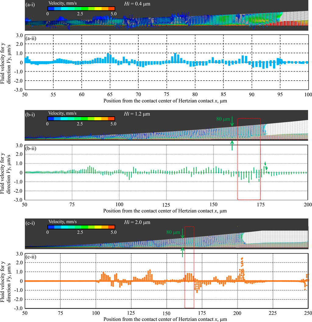
Figure 13. The Navier-Stokes Simulation results of different oil film thickness (A) Hi = 0.4, (B) Hi = 1.2, and (C) Hi = 2.0 μm. (i) Shows velocity and direction of oil, (ii) shows average velocity of y direction.
Next, the results for an outside oil film thickness Hi = 1.2 μm are shown in Figure 13B. The geometric distance between the contacting surfaces equals the particle diameter of 0.8 μm at x = 160 μm. Particles near the disc surface ride the upward flow in the y-axis direction at x = 178 μm, but are influenced by the downward flow in the y-axis direction in the range of x = 159–174 μm. This downward flow just before particles are geometrically trapped is assumed to push the particles against the disc surface. This result is thought to affect the amount of particle deposition and is consistent with the observation that the number of SiO2 particles deposited peaks around an outside oil film thickness of 1.4 μm, as shown in Figure 8.
Finally, for an outside oil film thickness Hi = 2.0 μm as shown in Figure 13C, an upward flow in the y-axis direction is generated at x = 205 μm where the air-liquid interface is formed between the contacting surfaces, suggesting that particles are drawn away from the disc surface. Additionally, an upward flow in the y-axis direction occurs again around x = 160 μm where the geometric gap equals the particle diameter, making it difficult for particles to remain.
These results align with the authors’ previous findings (Tokoroyama et al., 2024) as shown in Figure 14, which identified the generation of vortices as the cause of a peak in the number of particles entering within the range of 1 ≤ r ≤ 2 times the particle diameter, when the outside oil film thickness reaches an extremum.
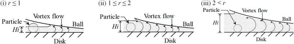
Figure 14. Schematic of a particle and vortex flow with different outside oil film thickness (Tokoroyama et al., 2024).
The results obtained in this study demonstrate how the van der Waals forces and the components that cause particles to separate from the incident flow act when using sapphire and glass disks. However, the effects of the incident flow, the shape, the hardness of the materials, and the hardness of the particles formed on the surfaces of the two contacting faces have not yet been considered. In the future, it will be necessary to widely apply observation techniques to anisotropic particles, ductile metal particles, and biomaterials, making it possible to design structures that suppress particle penetration. Furthermore, the wear particle problems such as human joint which is suffered by wear particles which cause undesirable reaction due to physically and chemically reaction in the body (Kovochich et al., 2018), cell-accelerated corrosion due to metal alloy wear debris (Bijukumar et al., 2020), immune toxicity caused by wear particles (Gill et al., 2012) are the formidable problems to be solved in near future. So, development of observing method of those particles or collecting them (Tokoroyama et al., 2018) should be achieved by several perspectives.
The prediction of particles’ entrainment when the particle size is less than 1 μm, the van der Waals forces on the disk surface become a significant source of force for particle penetration, but this had not been experimentally demonstrated. Furthermore, authors previously reported that a reverse flow vortex component forms in the direction away from the disk surface in front of the contact point, but this was only a hypothesis. Therefore, using Navier-Stokes numerical simulations to reveal the presence of a vortex at a specific location where particles are lifted off the disk surface is required. Using iFLAT, which enables in situ observation of particles entering the contact surfaces, the entry of fluorescent-stained particles was observed. Previous research reported that the number of particles entering reached an extreme value when the ratio r of the outside oil film thickness to the particle diameter was 1 ≤ r ≤ 2, but the mechanism was unclear. For particles to enter, they need to be present in the layer drawn towards the contact point. In this study, experiments were conducted based on the hypothesis that the proximity to and the amount of deposition on the disk side specimen surface are important parameters. Quartz and sapphire, with different Hamaker constants, were used in the experiments to clarify the effect of materials on the amount of particle deposition. The main conclusions obtained are shown below.
• The amount of particle deposition on the front side of the two contacting surfaces varies depending on the disk material, with sapphire disks consistently accumulating more particles than quartz.
• An experiment was conducted to verify the possibility that the differences in van der Waals forces, which were anticipated before the experiment, could attract particles to the substrate surface. As a result, the amount of particle deposition mentioned above is influenced by the van der Waals forces calculated from the Hamaker constant of the disk material. In relation to the force Fx = 0.64 nN acting on the particles from the fluid, the van der Waals forces were calculated as Gsapphire = 0.18 nN and Gquarts = 0.077 nN, respectively.
• Using Navier-Stokes simulation, calculations were performed on the flow between contact surfaces with outside oil film thicknesses of Hi = 0.4, 1.2, and 2.0 μm, and the y-axis directional velocity of the lubricant oil was calculated. The results indicated that when the outside oil film thickness was Hi = 1.2 μm, which is comparable to the particle diameter of 0.8 μm, there was a downward flow (i.e., towards the moving disk side) in the range from x = 159–174 μm, including x = 160 μm where the geometric gap between the two surfaces was 0.8 μm. This suggests a high possibility of particles being drawn between the contact surfaces. On the other hand, when the outside oil film thickness was Hi = 2.0 μm, at the position of the liquid-gas interface (x = 205 μm) formed between the lubricating oil and the gas between the contacting surfaces, there was a flow from the disk side towards the SUJ2 ball specimen direction, indicating the possibility of particles moving away from the disk. The above results are presumed to vary depending on factors such as the surface roughness of the counterpart material, the curvature radius of the ball, the viscosity of the lubricant, and the anisotropy of the particles. Therefore, it will be necessary to continue clarifying the entry of particles into the contact surfaces of automotive transmissions and gears in the future.
The original contributions presented in the study are included in the article/supplementary material, further inquiries can be directed to the corresponding author.
TT: Writing–original draft, Writing–review and editing, Formal Analysis, Investigation, Methodology, Visualization. MO: Formal Analysis, Investigation, Methodology, Writing–original draft. RZ: Formal Analysis, Investigation, Methodology, Writing–original draft. MM: Formal Analysis, Investigation, Methodology, Writing–original draft. RT: Formal Analysis, Investigation, Methodology, Writing–original draft. TY: Formal Analysis, Investigation, Methodology, Writing–original draft. HS: Formal Analysis, Investigation, Methodology, Writing–original draft. NU: Supervision, Writing–original draft.
The author(s) declare financial support was received for the research, authorship, and/or publication of this article. This paper is based on results obtained from a project, JPNP20004, subsidized by New Energy and Industrial Technology Development Organization (NEDO).
The authors acknowledge the support of Mr. Y. Asada, Mr. T. Sato, and Mr. T. Muramatsu at Univance corporation, Shizuoka, Japan, for supporting research fund and having discussion to perfume this work.
The authors declare that the research was conducted in the absence of any commercial or financial relationships that could be construed as a potential conflict of interest.
All claims expressed in this article are solely those of the authors and do not necessarily represent those of their affiliated organizations, or those of the publisher, the editors and the reviewers. Any product that may be evaluated in this article, or claim that may be made by its manufacturer, is not guaranteed or endorsed by the publisher.
Abdollah, M. F. B., Yamaguchi, Y., Akao, T., Inayoshi, N., Miyamoto, N., Tokoroyama, T., et al. (2012). Deformation-wear transition map of DLC coating under cyclic impact loading. Wear 274-275, 435–441. doi:10.1016/j.wear.2011.11.007
Abdollah, M. F. B., Yamaguchi, Y., Akao, T., Inayoshi, N., Umehara, N., and Tokoroyama, T. (2010). Phase transformation studies on the a-C coating under repetitive impacts. Surf. Coat. Technol. 205 (2), 625–631. doi:10.1016/j.surfcoat.2010.07.062
Aboua, K. A. M., Umehara, N., Kousaka, H., Tokoroyama, T., Murashima, M., Mabuchi, Y., et al. (2018a). Effect of carbon diffusion on friction and wear behaviors of diamond-like carbon coating against Cr-plating in boundary base oil lubrication. Tribol. Online 13 (5), 290–300. doi:10.2474/trol.13.290
Aboua, K. A. M., Umehara, N., Kousaka, H., Tokoroyama, T., Murashima, M., Mabuchi, Y., et al. (2019). Effect of carbon diffusion on friction and wear behaviors of diamond-like carbon coating against germanium in boundary base oil lubrication. Tribol. Lett. 67 (2), 65. doi:10.1007/s11249-019-1179-2
Aboua, K. A. M., Umehara, N., Kousaka, H., Tokoroyama, T., Murashima, M., Tasdemir, H. A., et al. (2018b). Effect of ZnDTP triboflim's morphology on friction behaviors of DLC coatings: tribofilm characterization by 3D scanning electron microscope observation. JAMDSM 12, JAMDSM0129. doi:10.1299/jamdsm.2018jamdsm0129
Alfred, G. E., Francis, T. B., and Leslie, G. P. (1958). Flow of a viscous liquid on a rotating disk. J. Appl. Phys. 29, 858–862. doi:10.1063/1.1723300
Azuma, N., Ozeki, H., Miki, K., Fukuzawa, K., Itoh, S., and Zhang, H. (2023). Quantitative measurement of squeeze flow distribution in nanogaps by particle image velocimetry using Quantum Dots. Tribol. Lett. 71, 112. doi:10.1007/s11249-023-01783-8
Bergström, L. (1997). Hamaker constants of inorganic materials. Adv. Colloid Interface Sci. 70, 125–169. doi:10.1016/S0001-8686(97)00003-1
Bijukumar, D. R., Salunkhe, S., Zheng, G., Barba, M., Hall, D. J., Pourzal, R., et al. (2020). Wear particles induce a new macrophage phenotype with the potential to accelerate material corrosion within total hip replacement interfaces. Acta Biomater. 101, 586–597. doi:10.1016/j.actbio.2019.10.039
Bukvić, M., Gajević, S., Skulić, A., Savić, S., Ašonja, A., and Stojanović, B. (2024). Tribological application of nanocomposite additives in industrial oils. Lubricants 12 (1), 6. doi:10.3390/lubricants12010006
Chang, S., Eichmann, S. L., Huang, T. Y. S., Yun, W., and Wang, W. (2017). Controlled design and fabrication of SERS-SEF multifunctional nanoparticles for nanoprobe applications: morphology-dependent SERS phenomena. J. Phys. Chem. C 121, 8070–8076. doi:10.1021/acs.jpcc.7b00688
Chang, S., Yun, W., Eichmann, S. L., Poitzsch, M. E., and Wang, W. (2019). Magnetic SERS composite nanoparticles for microfluidic oil reservoir tracer detection and nanoprobe applications. Appl. Nano Mater. 2, 997–1004. doi:10.1021/acsanm.8b02291
Dwyer-Joyce, R. S. (1999). Predicting the abrasive wear of ball bearings by lubricant debris. Wear 233–235, 692–701. doi:10.1016/S0043-1648(99)00184-2
Emslie, A. G., Bonner, F. T., and Peck, L. G. (1958). Flow of a viscous liquid on a rotating disk. J. Appl. Phys. 29, 858–862. doi:10.1063/1.1723300
Gajevic, S., Marković, A., Milojević, S., Ašonja, A., Ivanović, L., and Stojanović, B. (2024). Multi-objective optimization of tribological characteristics for aluminum composite using taguchi grey and TOPSIS approaches. Lubricants 12, 171. doi:10.3390/lubricants12050171
Ghosh, S. K., and Böker, A. (2019). Self-assembly of nanoparticles in 2D and 3D: recent advances and future trends. Macromol. Chem. Phys. 220, 1900196. doi:10.1002/macp.201900196
Gill, H. S., Grammatopoulos, G., Adshead, S., Tsialogiannis, E., and Tsiridis, E. (2012). Molecular and immune toxicity of CoCr nanoparticles in MoM hip arthroplasty. Trends Mol. Med. 18 (3), 145–155. doi:10.1016/j.molmed.2011.12.002
Hamrock, B. J., and Dowson, D. (1981). Ball bearing lubrication: the elastohydrodynamics of elliptical contacts.
Hashizume, N., Murashima, M., Umehara, N., Tokoroyama, T., and Lee, W. Y. (2021). In situ observation of the formation of MoDTC-derived tribofilm on a ta-C coating using reflectance spectroscopy and its effects on friction. Trib. Int. 162, 107128. doi:10.1016/j.triboint.2021.107128
Kassim, K. A. M., Tokoroyama, T., Murashima, M., Lee, W.-Y., Umehara, N., and Mustafa, M. M. B. (2021). Wear acceleration of a-C:H coatings by Molybdenum-derived particles: mixing and temperature effects. Tribol. Int. 159, 106944. doi:10.1016/j.triboint.2021.106944
Kassim, K. A. M., Tokoroyama, T., Murashima, M., and Umehara, N. (2020). The wear classification of MoDTC-derived particles on silicon and hydrogenated diamond-like carbon at room temperature. Tribol. Int. 147, 106176. doi:10.1016/j.triboint.2020.106176
Kovochich, M., Fung, E. S., Donovan, E., Unice, K. M., Paustenbach, D. J., and Finley, B. L. (2018). Characterization of wear debris from metal-on-metal hip implants during normal wear versus edge-loading conditions. J. Biomed. Mater. Res. Part B 106B, 986–996. doi:10.1002/jbm.b.33902
Lee, W. Y., Jang, Y. J., Umehara, N., Tokoroyama, T., and Murashima, M. (2020). Effect of defects on wear behavior in ta-C coating prepared by filtered cathodic vacuum arc deposition. Diam. Relat. Mater 105, 107789. doi:10.1016/j.diamond.2020.107789
Lee, W. Y., Tokoroyama, T., Jang, Y. J., and Umehara, N. (2018). Effect of substrate bias and temperature on friction and wear properties for ta-C coating prepared under different substrate bias voltages with filtered cathodic vacuum arc deposition. Tribol. Online 13 (5), 241–247. doi:10.2474/trol.13.241
Lee, W. Y., Tokoroyama, T., Jang, Y. J., and Umehara, N. (2019). Investigating running-in behavior to understand wear behavior of ta-C coating with filtered cathodic vacuum arc deposition. J. Tribol. 23, 38–47. Available at: https://jurnaltribologi.mytribos.org/v23/JT-23-38-47.pdf.
Milojević, S., Glišović, J., Savić, S., Bošković, G., Bukvić, M., and Stojanović, B. (2024). Particulate matter emission and air pollution reduction by applying variable systems in tribologically optimized diesel engines for vehicles in road traffic. Atmosphere 15 (2), 184. doi:10.3390/atmos15020184
Milojević, S., Savić, S., Mitrović, S., Marić, D., Krstić, B., Stojanović, B., et al. (2023). Solving the problem of friction and wear in auxiliary devices of internal combustion engines on the example of reciprocating air compressor for vehicles. Tech. Gaz. 30 (1), 122–130. doi:10.17559/TV-20220414105757
Milojević, S., and Stojanović, B. (2018). Determination of tribological properties of aluminum cylinder by application of Taguchi method and ANN-based model. J. Braz. Soc. Mech. Sci. Eng. 40, 571. doi:10.1007/s40430-018-1495-8
Nikas, G. K. (2007). Effects of operating conditions and friction on the entrapment of spherical debris particles in elliptical contacts. Proc. Institution Mech. Eng. Part J J. Eng. Tribol. 221 (6), 727–741. doi:10.1243/13506501JET283
Nikas, G. K. (2016). Algebraic equations for the pile-up geometry in debris particle indentation of rolling elastohydrodynamic contacts. J. Tribol. 138 (2), 021503. doi:10.1115/1.4031516
Nikas, G. K. (2020). Particle Entrapment in Line Elastohydrodynamic Contacts and the Influence of Intermolecular (van der Waals) Forces. Lubricants 8 (5), 60. doi:10.3390/lubricants8050060
Nilsson, R., Dwyer-Joyce, R. S., and Olofsson, U. (2006). Abrasive wear of rolling bearings by lubricant borne particles. Proc. Institution Mech. Eng. Part J J. Eng. Tribol. 220 (5), 429–439. doi:10.1243/13506501J00205
Rabinovich, Y. I., Adler, J. J., Ata, A., Singh, R. K., and Moudgil, B. M. (2000). Adhesion between nanoscale roughs surfaces: I. Role of asperity geometry. J. Colloid Interface Sci. 232, 10–16. doi:10.1006/jcis.2000.7167
Strubel, V., Fillot, N., Cavoret, J., Vegne, P., Mondelin, A., and Maheo, Y. (2016). Particle entrapment in hybrid lubricated point contacts. Tribol. Trans. 59 (4), 768–779. doi:10.1080/10402004.2015.1106631
Strubel, V., Fillot, N., Ville, F., Cavoret, J., Vergne, P., Mondelin, A., et al. (2017a). Particle entrapment in rolling element bearings: the effect of ellipticity, nature of materials, and sliding. Tribol. Trans. 60 (2), 373–382. doi:10.1080/10402004.2016.1168901
Strubel, V., Simoens, S., Vergne, P., Fillot, N., Ville, F., Hajem, M. E., et al. (2017b). Fluorescence tracking and µ-PIV of individual particles and lubricant flow in and around lubricated point contacts. Tribol. Lett. 65, 75. doi:10.1007/s11249–017–0859–z
Tokoroyama, T., Kamiya, T., Ahmed, NABH, and Umehara, N. (2018). Collecting micrometer-sized wear particles generated between DLC/DLC surfaces under boundary lubrication with electric field. JSME Mech. Eng. Lett. 4, 18–00089. doi:10.1299/mel.18-00089
Keywords: in-situ, fluorescent staining, Rhodamine B, silane coupling, oil film thickness, Navier-Stokes simulation
Citation: Tokoroyama T, Okashita M, Zhang R, Murashima M, Tsuboi R, Yoshida T, Shiomi H and Umehara N (2024) The mechanism of small wear particles entrainment in friction under boundary lubrication. Front. Mech. Eng. 10:1470312. doi: 10.3389/fmech.2024.1470312
Received: 25 July 2024; Accepted: 23 August 2024;
Published: 20 September 2024.
Edited by:
Hikaru Okubo, Yokohama National University, JapanReviewed by:
Saša Milojević, University of Kragujevac, SerbiaCopyright © 2024 Tokoroyama, Okashita, Zhang, Murashima, Tsuboi, Yoshida, Shiomi and Umehara. This is an open-access article distributed under the terms of the Creative Commons Attribution License (CC BY). The use, distribution or reproduction in other forums is permitted, provided the original author(s) and the copyright owner(s) are credited and that the original publication in this journal is cited, in accordance with accepted academic practice. No use, distribution or reproduction is permitted which does not comply with these terms.
*Correspondence: Takayuki Tokoroyama, dGFrYXl1a2kudG9rb3JveWFtYUBtYWUubmFnb3lhLXUuYWMuanA=
Disclaimer: All claims expressed in this article are solely those of the authors and do not necessarily represent those of their affiliated organizations, or those of the publisher, the editors and the reviewers. Any product that may be evaluated in this article or claim that may be made by its manufacturer is not guaranteed or endorsed by the publisher.
Research integrity at Frontiers
Learn more about the work of our research integrity team to safeguard the quality of each article we publish.