- 1Department of Mechanical Engineering, Faculty of Science and Engineering, Kindai University, Higashiosaka City, Japan
- 2Major in Mechanical Engineering, Graduate School of Science and Engineering, Kindai University, Higashiosaka City, Japan
Demands for improved fuel efficiency in automobiles and other vehicles have led to smaller, lighter power transmission device which result in high surface contact stress and a thin oil film, which in turn tends to cause the temperature of rolling bearings to rise. The most common temperature measurement method is to touch a thermocouple against the inner and outer rings, and this method has been used for many years. However, the method using thermocouples can only measure temperatures in a limited range near the measurement point. The authors applied the Seebeck effect, a phenomenon in which an electromotive force is generated when different metals are connected and a temperature difference is applied to bearings, to a method of measuring bearing raceway temperatures called the dynamic thermocouple method. In the dynamic thermocouple method, the average value of each contact points between the different metals generates the emf (electromotive force), so the temperature rise of all the each rolling elements in contact becomes the average value, and the exact point of temperature rise is not clear. Therefore, all but one rolling element was changed to electrically insulating zirconia balls. With this method, the contact points between many different metals became one, making it possible to identify the locations of temperature rises on the raceway surface. This method makes it possible to directly measure the temperature change of the raceway. The results of temperature measurements of the raceway surface using two types of bearings with different raceway accuracy showed a clear difference of temperature. The bearing with a poor raceway accuracy showed a temperature rise in the unloaded zone, and slippage was observed when the behavior of the rolling element was checked with a high-speed camera. Furthermore, in bearings with good raceway accuracy, the temperature of the raceway surface remained almost constant even in the non-load zone. By using the dynamic thermocouple method and observing the rolling elements with a high-speed camera, it was possible to correlate the bearing temperature rise with the behavior of the rolling elements.
1 Introduction
As global warming countermeasures, there is a demand for more efficient automobiles and other machines. Tribological optimization of materials is also being considered to improve the sliding surfaces of pistons and cylinders in internal combustion engines, which will contribute to reducing particulate matter emissions by reducing fuel consumption, and therefore reducing wear on the materials in sliding contact. It contributes to the reduction in harmful gases in the air (Milojevic et al., 2024). Another approach from the lubrication field is to improve lubricants by adding nanotube additives (Bukvic et al., 2024). In addition, efforts are being made to reduce friction loss in rolling bearings for automobiles. There are three technical methods for reducing friction loss in rolling bearings. The first is to change the design of the bearing without changing the main dimensions. The second is to reduce the size of the bearing to reduce torque and weight, and the third is to optimize lubrication in terms of lubricating oil type and bearing materials (Sada, 2017). While two kinds of rolling bearings (ball and roller bearings) are used to reduce friction in internal combustion engine components, allowing rotation and relative motion of mechanical elements, but also, these rolling bearing reducing friction technologies in ICEV automotives are being transferred in electric vehicle design (Farfan-Cabrera, 2019). Due to the development for more compact and lightweight power transmission device and the use of low-viscosity oil to improve fuel efficiency in automobiles and other machines, the temperature of rolling bearings tends to rise due to high contact stress and a thin oil film. Following common rolling bearing failure causes can be classified, with their percentage shares:(1) insufficient amount of lubricant: 15%; (2) inadequate selection of lubricant: 20%; (3) aged lubricant (wear products, additive depletion): 20%; (4) solid particle contamination of lubricant: 20%; (5) liquid contamination of lubricant: 5%; (6) inadequate selection of bearing: 10%; (7) handling induced defects: 5%; (8) mounting faults: 5%; (9) bearing material and production faults: less than 1%. As it can be seen about 80% of bearing failures are associated with the tribological causes (cause 1–5) (Vencl et al., 2017). Reducing friction and wear of rolling bearing elements can be achieved by choosing the right structure, choosing materials with a low friction coefficient and high wear resistance and using appropriate types of lubricants for lubrication (Janic et al., 2015). The fault detection and diagnosis along with condition monitoring and rotating machinery have critical importance for early diagnosis to prevent severe damage of infrastructure in industrial environments. Basic signals used for condition monitoring include vibration, noise, and temperature. Vibration and noise are sensitive to noise, but have the advantage that they can be used for early failure detection and diagnosis. Conversely, temperature cannot be used for early failure detection and diagnosis, but it has the characteristics of being noninvasive and resistant to noise (AlShorman et al., 2020). There are two types of temperature measurement: contact type, which uses thermocouples, etc. (Takabi and Khonsari, 2013), and non-contact type, which uses the intensity of infrared rays emitted from an object (Usamentiaga et al., 2014). Contact type measurement is characterized by fixed-point observation and good measurement accuracy, while non-contact type is characterized by the ease of visually understanding the temperature distribution. The most common temperature measurement method is to touch a thermocouple against the inner and outer rings, which has been used conventionally for railroad bearings (Tarawneh et al., 2008) and for development and verification of aircraft engines (Flouros, 2006). However, the method using thermocouples can only determine temperatures in a limited range in the vicinity of the measurement point. Therefore, a technique using infrared rays that detects and visualizes heat to clarify the bearing temperature distribution was used (Jakubek et al., 2021). This method enables visualization of thermal data. In addition, a new technique is the measurement with a sensor that can detect the physical quantity from the amount of wavelength shift, in which the Bragg center reflection wavelength shifts sensitively to temperature by having a short segment in the core of an optical fiber line with a synchronous refractive index modulation of about the wavelength of propagating light (Liu et al., 2013; Dong et al., 2015). Furthermore, a case of temperature measurement by sputtering NiCr and NiSi, which are used as materials for thermocouples, into a thin-film state thermocouple and pressing it onto the edge of a rolling element has been reported (Cui et al., 2022). However, the methods reported so far have not measured the surface temperature of the raceway, which is assumed to be the hottest part of a rolling bearing. Developing a method to continuously measure the surface temperature of rolling bearing raceways is important, as it relates to study into reducing friction loss and improving the reliability of rolling bearings used in automobiles and other machines. Therefore, the authors tried to measure the surface temperature of the raceway surface by using the dynamic thermocouple method, which applies the Seebeck effect, a phenomenon in which an electromotive force is generated. The raceway surface temperature was measured by using the inner ring and rolling elements made of the same material, while the outer ring was made of a different metal. Usually, AISI52100 or carburized steel (AISI4320, AISI9310) is used as the bearing material (Zaretsky, 2012). Basically, the same material is used for the inner ring, outer ring, and rolling elements, but in this study, hardened dissimilar metals were used to generate electromotive force.
2 Measurement method
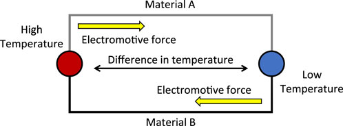
This study proposes a dynamic thermocouple method for measuring the temperature of the raceway of rolling bearings. The dynamic thermocouple method is based on the Seebeck effect. The Seebeck effect is a phenomenon in which an electromotive force is generated and an electric current flow when there is a temperature difference between two different metals at each contact point in a closed circuit, as shown in Figure 1.
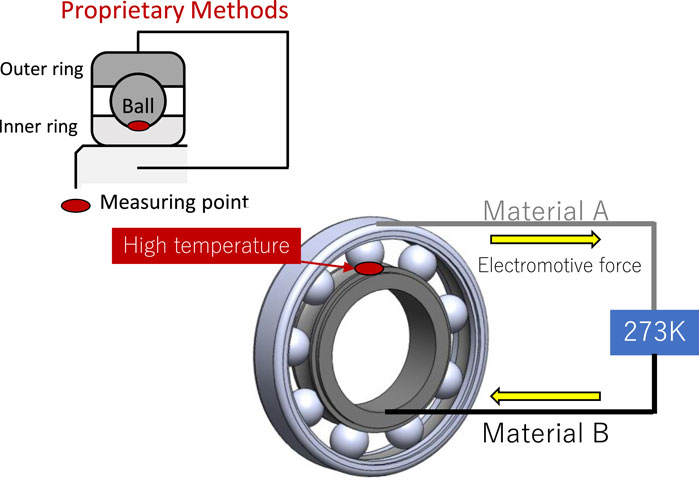
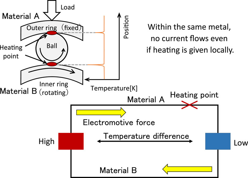
To apply the Seebeck effect to rolling bearings, different materials were used for the outer ring and rolling element material A and the inner ring material B, so that the rolling element and inner ring raceway temperatures could be measured. Figure 2 shows the details. When measuring raceway temperatures using the dynamic thermocouple method, the law of homogeneous circuits was used because rolling bearings generate heat at two points: between the inner ring and rolling elements and between the outer ring and rolling elements. The homogeneous circuit law states that when two different metals are assembled in a closed circuit, the emf is affected only by the temperature difference at the contact point and not by heating in the middle of the circuit, even if heating occurs in the middle of the circuit. Therefore, when measuring the temperature of the inner ring raceway, it is not affected by the heat generated by the outer ring raceway. Figure 3 shows an explanation of this. In this case, the outer ring and rolling elements are made of material A and the inner ring is made of material B. The heat generated between the outer ring and rolling elements does not affect the measurement on the inner ring raceway surface because the heat generated is within the same material.
2.1 Composition of rolling bearings
In the dynamic thermocouple method, the average value of each contact points between the different metals generates the emf (electromotive force), so the temperature rise of all the each rolling elements in contact becomes the average value, and the exact point of temperature rise is not clear. Therefore, all but one rolling element was changed to electrically insulating zirconia balls. With this method, the contact points between many different metals became one, making it possible to identify the locations of temperature rises on the raceway surface. This method made it possible to directly measure the temperature change of the raceway. As shown in Figure 4, the contact point between the different metals became one, and the temperature rose point on the raceway surface could be identified. The breakdown voltage of the zirconia sphere used in this study was large. The voltage measured in this study was on the order of 10 mV at the maximum, which did not exceed the breakdown voltage, and thus was considered sufficient for insulation. The metal material specifications in the figure are those of JIS (Japanese Industrial Standards).
2.2 Calibration of electromotive force
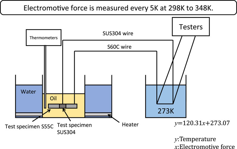
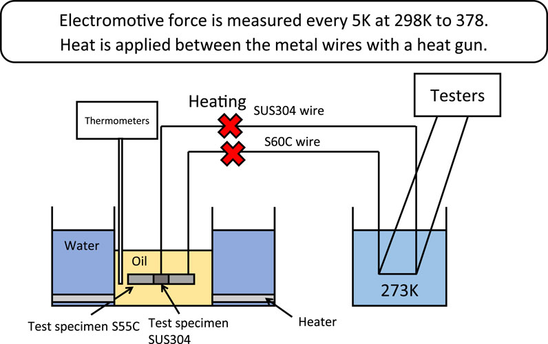
Connect the test piece and the metal wire in the following combinations. Combine the test piece (JIS S55C) and metal wire (JIS S60C) and the test piece (JIS SUS304) and metal wire (JIS SUS304) in a crisscross pattern as shown in Figure 5. Insert the combined test piece and thermometer into a beaker filled with oil. Place the thermos in a heater filled with water. To make the zero contact, fill the thermos with ice water and check that the temperature is 273 K with a thermometer. Insert a metal wire other than the one connected to the test piece into the thermos (zero contact point) at the connection point of the extension cord. Insert and connect the tester to the other end of the extension cord. The emf at the starting temperature of the calibration test was measured, the temperature of the oil in the beater was increased by the heater in 5K increments from 298 to 348K, and the emf was measured at each temperature. The relationship between the obtained temperatures and emf was shown in Figure 5. The test to confirm the law of homogeneous circuits using the test specimens was conducted in the same manner as the emf calibration test described above. Here, the thermometer used was MT-851, MOTHERTOOL, Japan, and the tester was MS8218, MASTACH, China.
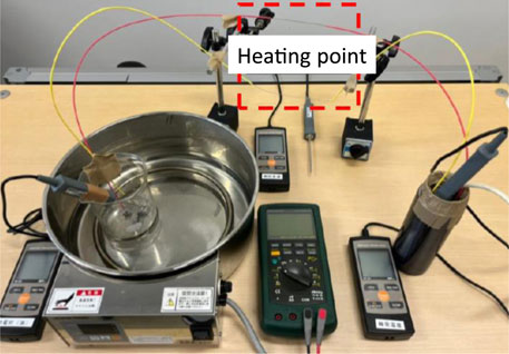
The electromotive force at each temperature is measured, and at the same time, the law of homogeneous circuits was confirmed to be valid by heating the middle point of the metal wire S60C and SUS304 with a heat gun. Figures 6, 7 below show a schematic diagram of the homogeneous circuit law verification test using a test specimen and the actual test. The relationship between temperature and emf did not change when the middle point was heated with a heat gun.
2.3 Raceway surface temperature measurement test
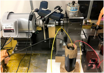
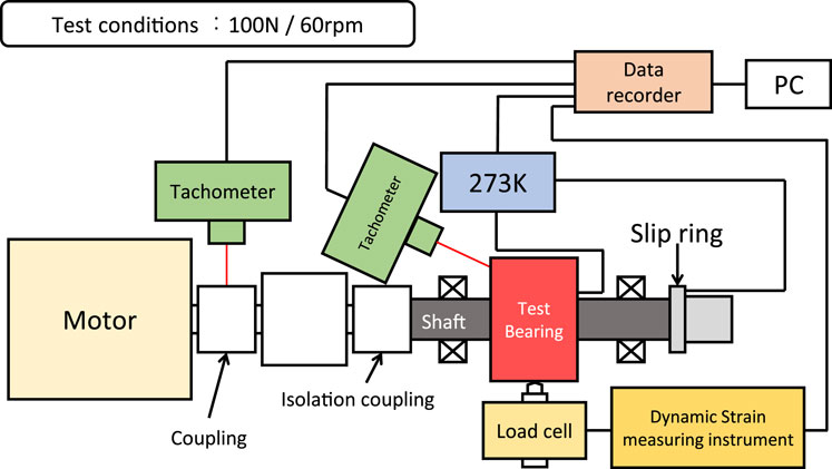
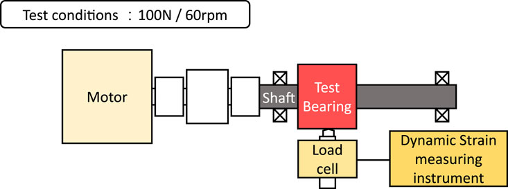
Figure 8 shows the experimental setup for a test to measure the raceway temperature of a rolling bearing using the dynamic thermocouple method. The shaft was fixed to the motor, and the load was varied by applying a load to the bearing measuring a load cell. The test bearing and the test shaft must be insulated. An insulating coupling was used between the test shaft and the motor, and a ceramic ball bearing was used as the bearing supporting the test shaft. A slip ring was attached to the other end of the test shaft to extract the electromotive force from the rotating element. A data recorder was used to measure the emf. A schematic diagram of the test apparatus is shown in Figure 9. Here, the tachometer used was HT-5500, Ono Sokki Co., LTD., Japan, the data recorder was DC-004P, Tokyo Measuring Instrument Co., Ltd., Japan, and the load cell was LUK-A-5KNSA1, KTOWA ELECTRONIC INSTRUMENT Co., LTD., Japan. The test was conducted with a bearing load of 100 N and a rotational speed of 60 rpm. The load and rotational speed conditions were set so that test could be carried out safely, since a safety cover could not be attached in order to measure temperature and the rotational speed of the rolling elements.
3 Temperature and rolling element behavior measurement test
The test focused on the accuracy of the bearing outer ring and compared two types of bearings. To improve the accuracy of the bearing inner and outer rings, the bearing material was also changed. Basically, the same procedure was used to prepare for the test as for the material with poor bearing accuracy. The material differences are shown in Table 1.
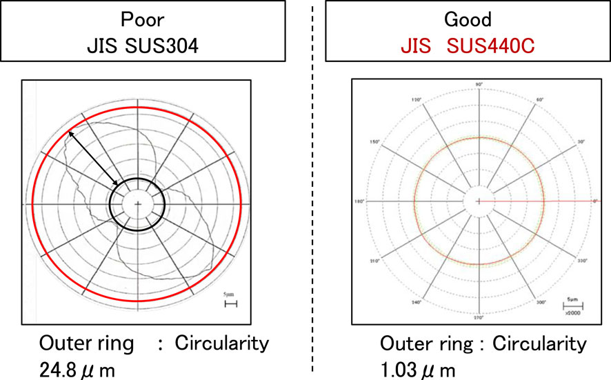
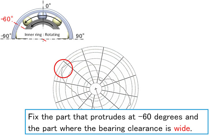
Next, a comparison of the roundness of the bearing outer rings is shown in Figure 10. The accuracy of the inner ring has also improved (4.73 μm ⇒ 0.35 μm). However, the inner ring rotates and the outer ring is stationary under the operating conditions and the roundness of the outer ring is extremely poor (24.82 μm ⇒ 1.03 μm). Figure 11 shows the installation method of the outer ring with poor bearing accuracy. The bearing load is applied at 0°, and the left and right. The angle was determined to be −60°. The point where the circularity increases was set to −60°.
3.1 Temperature measurement test results
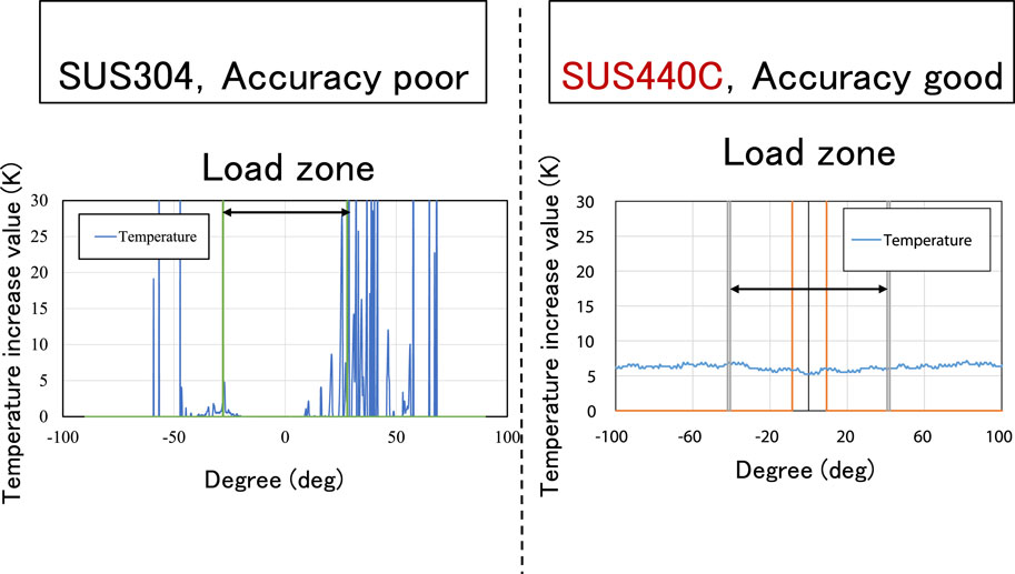
To compare the temperature rise caused by differences in raceway accuracy, Figure 12 shows the results for bearings with poor and good accuracy. Figure 12 shows that when bearing accuracy is poor, the temperature rises outside the load distribution area or at points where the rolling element load is small. By observing Figure 12, it was confirmed that the temperature rise pattern differs depending on the bearing accuracy. In the case of poorly accurate bearings, the rolling elements showed a large amount of slippage in the load zone, which was thought to be the cause of the increase in temperature on the raceway surface.
3.2 Confirmation of reproducibility
To confirm the reproducibility of the temperature measurement, we confirmed the reproducibility under the condition of good accuracy. The results are shown in Figure 13. The temperature rise value was almost the same for the first and second measurements, and reproducibility was confirmed. No difference in reproducibility due to noise or the like was observed. In this test, the low-pass filter used for temperature measurement was 50 Hz, and no high-pass filter was set.
3.3 Rolling element behavior measurement methods
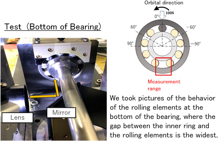
Figure 14 shows a schematic of the apparatus used to measure the rolling element behavior. The rolling elements (zirconia balls) were marked to make their behavior easier to understand during the observation. A high-speed camera was used to check the rolling element behavior of the bearing by taking pictures through a mirror as shown in Figure 15.
3.4 Rolling element behavior measurement results
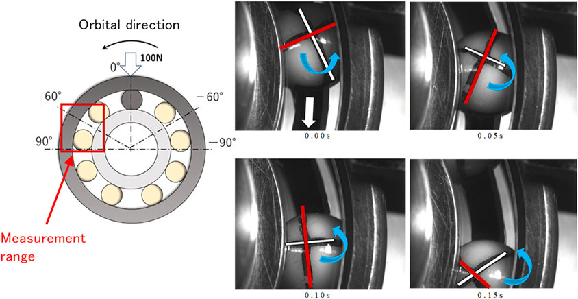
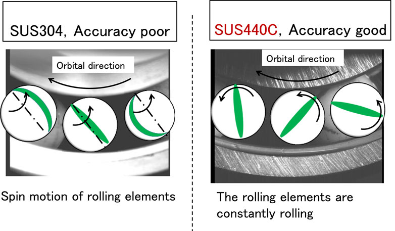
Figure 16 shows the results of the observation of the rolling element behavior in the lateral portion of the bearing with good accuracy. The measurement start time was set at 0.000 s, and the results were recorded every 0.050 s. Note that the image was taken through a mirror, so the direction of rotation is reversed from the actual direction of rotation. When we checked the behavior of the rolling elements on the side of the bearing, we found that they were rotating with almost no slippage. Figure 16 shows the method used to observe the rolling element behavior at the bottom of the bearing. The measurement start time was set at 0.000 s, and the data was recorded every 0.050 s. The image was taken through a mirror, so the direction of rotation was reversed from the actual direction of rotation. Figure 17 shows the measurement results. It was confirmed that the rolling element did not slide much even at the bottom of the bearing when the raceway accuracy was good, and that the rolling element was almost rolling. From Figure 18, it can be seen that in bearings with poor raceway surface accuracy, the rolling elements spin and slip along an axis perpendicular to the direction of revolution.
4 Research results
Due to various backgrounds, rolling bearings are used more and more in harsh environments, and damage is more likely to occur on the raceway. In this study, we focused on the cause of damage to the raceway from the viewpoint of temperature rise, and measured the temperature of the raceway using the dynamic thermocouple method and the homogeneous circuit law. The temperature rise of the bearing raceways was also compared with different bearing raceway accuracy.
1) For bearings with poor raceway accuracy, the temperature rose in the non-loading zone, and slippage was observed when the rolling element behavior was checked by a high-speed camera. For bearings with good raceway accuracy, the temperature of the raceway remained almost constant in the non-loading zone.
2) When the behavior of the rolling elements in the lower part of the bearing (non-loading zone) was checked with a high-speed camera, the rolling elements in the bearing with a poor raceway accuracy exhibited spinning and sliding motion around an axis perpendicular to the orbital direction. In the case of a bearing with a good raceway accuracy, the rolling element was observed to be in pure rolling motion.
The above results indicate that if the accuracy of the raceway surface is poor, the bearing clearance changes significantly and no load is applied in the unloaded zone, and the direction of rotation is not constant. In addition, the temperature of the raceway cannot be detected because contact between the inner ring and rolling elements is unlikely to occur. The better the raceway accuracy and the smaller the bearing clearance, the more constant the direction of rotation becomes even in the unloaded range. Therefore, the temperature was considered to be almost constant because there was little sliding of the rolling elements. Therefore, it is concluded that the accuracy of the bearing raceway has a significant effect on the temperature rise of the raceway.
5 Conclusion
A useful method to continuously measure the surface temperature of the raceway of rolling bearings was developed, and confirmed that the temperature generation patterns differ depending on whether the bearing accuracy is good or bad. This method will contribute to improving design or calculating methods for reducing friction and confirming reliability of rolling bearings. The Seebeck effect and the law of homogeneous metals are common knowledge in the world of physics, but by appropriately combining these two laws, we were able to propose a method for continuously measuring the temperature of rolling bearing raceways, which was previously very difficult. We believe that the fact that we have demonstrated a quantitative evaluation method for areas where no suitable measurement method existed previously will lead to useful developments in mechanical engineering.
Data availability statement
The original contributions presented in the study are included in the article/Supplementary Material, further inquiries can be directed to the corresponding author.
Author contributions
HT: Investigation, Methodology, Validation, Visualization, Writing–review and editing. NU: Data curation, Investigation, Validation, Visualization, Writing–review and editing. YT: Conceptualization, Methodology, Project administration, Supervision, Writing–original draft.
Funding
The author(s) declare that financial support was received for the research, authorship, and/or publication of this article. This research is supported by JSPS Grant-in-Aid for Scientific Research (C) 21K03843.
Conflict of interest
The authors declare that the research was conducted in the absence of any commercial or financial relationships that could be construed as a potential conflict of interest.
Publisher’s note
All claims expressed in this article are solely those of the authors and do not necessarily represent those of their affiliated organizations, or those of the publisher, the editors and the reviewers. Any product that may be evaluated in this article, or claim that may be made by its manufacturer, is not guaranteed or endorsed by the publisher.
Supplementary material
The Supplementary Material for this article can be found online at: https://www.frontiersin.org/articles/10.3389/fmech.2024.1462450/full#supplementary-material
References
AlShorman, O., Irfan, M., Saad, N., Zhen, D., Haider, N., Glowacz, A., et al. (2020). A review of artificial intelligence methods for condition monitoring and fault diagnosis of rolling element bearings for induction motor. Shock Vib. 2020, 1–20. Article ID 8843759. doi:10.1155/2020/8843759
Bukvic, M., Gagevic, S., Skulic, A., Savic, S., Asonja, A., and Stojanovic, B. (2024). Tribological application of nanocomposite additives in industrial oils. Lubricants 12 (6), 1–21. doi:10.3390/lubricants12010006
Cui, Y., Gao, P., Tang, W., Mo, G., and Yin, J. (2022). Adaptive thin film temperature senor for bearing's elements temperature measurement. Sensors 22 (2838), 1–17. doi:10.3390/s22082838
Dong, Y., Zhou, Z., Liu, Z., and Zheng, K. (2015). Temperature field measurement of spindle ball bearing under radial force based on fiber Bragg grating sensors. Adv. Mech. Eng. 7 (12), 1–6. doi:10.1177/1687814015620332
Farfan-Cabrera, L. I. (2019). Tribology of electric vehicles: a review of critical components, current state and future improvement trends. Tribol. Int. 138 (2019), 473–486. doi:10.1016/j.triboint.2019.06.029
Flouros, M. (2006). Correlations for heat generation and outer ring temperature of high speed and highly loaded ball bearings in an aero-engine. Aerosp. Sci. Technol. 10 (2006), 611–617. doi:10.1016/j.ast.2006.08.002
Jakubek, B., Grochalski, K., Rukat, W., and Sokol, H. (2021). Thermovision measurement of rolling bearings. Measurement 2021, 1–25. doi:10.1016/measurement.2021.110512
Janic, N., Adamovic, Z., Nikolic, D., Asonja, A., and Stojanovic, B. (2015). Impact of diagnostics state model to the reliability of motor vehicles. J. Balkan Tribol. Assoc. 21 (2), 452–463.
Liu, M., Zhang, E., Zhou, Z., Tan, Y., and Liu, Y. (2013). Measurement of temperature field the spindle of machine tool based on optical fiber Bragg grating sensors. Adv. Mech. Eng. 2013, 1–6. Article ID 940626. doi:10.1155/2013/940626
Milojevic, S., Glisovic, J., Savic, S., Boskovic, G., Bukvic, B., and Stojanovic, B. (2024). Particulate matter emission and air pollution reduction by applying variable systems in tribologically optimized diesel engines for vehicles in road traffic. Atmosphere 15 (184), 184–225. doi:10.3390/atmos15020184
Sada, T. (2017). Loss reduction of rolling bearings for automobile. Tribol. Online 12 (3), 94–98. doi:10.2474/trol.12.94
Takabi, J., and Khonsari, M. M. (2013). Experimental testing and thermal analysis of ball bearings. Tribol. Int. 60 (2013), 93–103. doi:10.1016/j.triboint.2012.10.009
Tarawneh, C., Cole, K., Wilson, B., and Alnaimat, F. (2008). Experiments and models for the thermal response of railroad tapered-roller bearings. Int. J. Heat Mass Transf. 51 (25-26), 5794–5803. doi:10.1016/j.ijheatmasstransfer.2008.05.011
Usamentiaga, R., Venegas, P., Guerediaga, J., Vega, L., Molleda, J., and Bulnes, F. G. (2014). Infrared thermography for temperature measurement and non-destructive testing. Sensors 2014 (14), 12305–12348. doi:10.3390/s140712305
Vencl, A., Gasic, V., and Stojanovic, B. (2017). Fault tree analysis of most common rolling bearing tribological failures. IOP Conf. Ser. Mater. Eng. 174, 012048–12110. doi:10.1088/1757-899X/174/1/012048
Keywords: rolling bearing, temperature, seebeck effect, dynamic thermocouple, law of homogeneous, raceway, electromotive force
Citation: Tamae H, Ueda N and Tozaki Y (2024) A study of measurement of raceway direct measurement of rolling bearings. Front. Mech. Eng. 10:1462450. doi: 10.3389/fmech.2024.1462450
Received: 10 July 2024; Accepted: 27 September 2024;
Published: 31 October 2024.
Edited by:
Sorin-Cristian Vladescu, King’s College London, United KingdomReviewed by:
Aleksandar Ašonja, Business Academy University, SerbiaSaša Milojević, University of Kragujevac Faculty of Engineering, Serbia
Copyright © 2024 Tamae, Ueda and Tozaki. This is an open-access article distributed under the terms of the Creative Commons Attribution License (CC BY). The use, distribution or reproduction in other forums is permitted, provided the original author(s) and the copyright owner(s) are credited and that the original publication in this journal is cited, in accordance with accepted academic practice. No use, distribution or reproduction is permitted which does not comply with these terms.
*Correspondence: Yasuyoshi Tozaki, dG96YWtpQG1lY2gua2luZGFpLmFjLmpw
 Hiromu Tamae1
 Yasuyoshi Tozaki