 Shervin Azadi
 Ali Abjadi1*
 Hossein Afshar
- 1Department of Mechanical Engineering, South Tehran Branch, Islamic Azad University, Tehran, Iran
- 2Department of Mechanical Engineering, East Tehran Branch, Islamic Azad University, Tehran, Iran
In today’s world, research on cooling systems that can effectively reduce the cooling time of heat sinks and enhance heat transfer efficiency in a shorter duration is extremely crucial. This experimental study analyzed the cooling time by simultaneously utilizing two cooling techniques. This involved the passage of ferrofluid (Fe3O4/water) through three channels of a heat sink under the influence of a magnetic field, as well as the application of an air impingement jet on the heat sink’s surface. A novel plate-fin heat sink with dimensions of 40 mm (L) × 31.32 mm (W) × 23.5 mm (H) consists of three channels with a diameter of 3 mm for crossing ferrofluid flow and 24 channels on the top of the heat sink for crossing the air was designed and built for the study. The heat sink was exposed to an air impingement jet and an external magnetic field simultaneously. Multiple tests were conducted to determine the convective heat transfer coefficients of the heat sink over time under specific conditions, including a magnetic field of 800 G, a volume fraction of 3%, a Reynolds number of 600 for the ferrofluid, and a mass flow rate of 0.1 kg/s. It was discovered that using the combined method of magnetic field and impingement jet (MF-IJ) compared to cooling by air impingement jet with the simultaneous passage of pure water through the ferrofluid channels (Water-IJ), as well as the ferrofluid flow under a magnetic field without the impingement jet (MF) methods for the designed heat sink, can increase the maximum heat transfer coefficient by 27.4% and 46.4%, respectively. The findings of this study suggest that using the MF-IJ cooling method as a flow control mechanism, along with this innovative geometry, can reduce the cooling time of the heat sinks.
1 Introduction
Flow control refers to any method by which fluid flow is regulated in a desired manner. Over the past few decades, advancements in flow control have been made through the utilization of various mechanisms, including pulse jet (Abdolahipour, 2023), modulated pulse jet (Abdolahipour et al., 2021; Abdolahipour et al., 2022a; Abdolahipour et al., 2022b), surface acoustic waves (Noori et al., 2020a; Noori et al., 2020b; Noori et al., 2021; Rahni et al., 2022; Shams Taleghani and Sheikholeslam Noori, 2022), plasma actuators (Mirzaei et al., 2012; Taleghani et al., 2012; Salmasi et al., 2013; Mohammadi and Taleghani, 2014; Taleghani et al., 2018), and subcavity (Bhaduri et al., 2024). These developments have proven instrumental in addressing engineering challenges and requirements. These methods offer significant potential for achieving engineering objectives, such as improvement of heat transfer and drag reduction. Moreover, extensive studies have been conducted on improving heat transfer using a magnetic field (Sadighi et al., 2022; Sadighi et al., 2023a; Sadighi et al., 2023b). Based on studies conducted thus far, another application of flow control is improving heat transfer in heat exchangers (Shabi et al., 2024). The electronics industry is confronted with a major challenge: achieving a low and monotone temperature dispensation on the surface of heat sink body, while also maximizing convective heat transfer. It is imperative to thoroughly study and explore different cooling methods for heat sinks as the use of electronic devices and their subsequent heat production continue to increase. The potential of advanced cooling technologies is to significantly improve thermal performance in cooling heat sinks, while also reducing greenhouse gas emissions and minimizing the environmental impact of cooling systems. Nevertheless, despite the numerous researches on heat sink cooling methods, there is still a lack of research on the reduction of cooling time in the combined method of magnetic field and impingement jet (MF-IJ) and the influence of air jet transfer channels in this method. In a numerical study conducted by Azadi et al. (2023), researchers found that, using of the MF-IJ method can lead to improvement the heat transfer coefficient by 32% in the heat sink. Ferrofluid is a type of nanofluid, has shown remarkable magnetization properties and outstanding thermophysical properties. Combining these unique characteristics has made it highly effective in cooling applications. The magnetization properties of ferrofluid allow it to respond to magnetic fields, making it suitable for applications where heat needs to be efficiently transferred or removed. By applying a magnetic field, the ferrofluid can be directed to specific areas and enhancing heat transfer within a system. This magnetic responsiveness allows for precise control and adjustment of cooling mechanisms, making ferrofluid a proper option for cooling electronic devices and other heat-generating components (Hwang et al., 2022). As yet, numerous studies have been carried out on investigating the increase of heat transfer using ferrofluid subject the impact of a magnetic field: Hai et al. (2023) studied the hydrothermal efficiency of thermal management devices by integrating active and passive heat transfer techniques. Specifically, the focus was on analyzing the performance of pin-finned heat sinks when a magnetic field is present. The analysis was conducted by numerically studying the flow of a Fe3O4 ferrofluid with a nanoparticle concentration ratio of 2% inside different pin-finned heat sink configurations (squares, circles, and triangles). Shahsavar et al. (2023), conducted an experimental study on the effect of ferrofluid flow inside the rifled tube under vibration and rotational magnetic field (RMF). The investigators discovered that the application of vibration can improve hydrothermal performance by disrupting the thermal boundary layer. Additionally, they found that using a magnetic field can enhance the mixing of ferrofluids. Wiriyasart et al. (2023), studied the heat transfer performance of a thermoelectric cooling system combined with a wavy channel heat sink at various magnetic distances. Studies have shown that, utilization of pulsating flow has been shown to significantly enhance thermal efficiency, leading to an approximate improvement of 23%. Hashemi et al. (2012), conducted a study where they examined how the heat transfer coefficient is influenced by the channel aspect ratio and porosity in a miniature plate-fin heat sink. The investigators discovered a straight relationship among the convective heat transfer and parameters they studied, namely, the porosity and channel aspect ratio. In recent years, many researchers have been exploring the use of a magnetic field to improve heat dissipation. (Li and Xuan, 2009; Zamzamian et al., 2011; Selvakumar and Suresh, 2012; Bezaatpour and Goharkhah, 2019; Zhong et al., 2021). Furthermore, Ashjaee et al. (2015) conducted an experiment on the influence of magnetic field on the pressure drop and convective heat transfer of a magnetic nanofluid in a tiny heat sink. Results showed, the presence of ferrofluid results in a maximum of 14% enhancement in heat transfer contrasted to pure water. This improvement in heat transfer is increased by 38% when 1200G magnetic field intensity is applied. Fateh et al. (2024) found that applying a magnetic field to ferrofluids enhances heat transfer by altering their flow characteristics. The impact of a constant magnetic field on laminar ferrofluid flow was investigated, and the results showed that the magnetic field significantly improved fluid acceleration and heat transfer. This led to the creation of recirculation zones that enhanced fluid mixing. Suqi et al. (2024) have studied the simultaneous use of a magnetic field, ferrofluid, and turbulator, along with changes in the cross-section of the absorber tube and finally the numerical results showed that these proposed modifications led to improvements in the parameters. Neural network modeling was utilized to predict the total rate of entropy generation and useful heat generation under the influence of a magnetic field. The application of impingement jet (IJ) to improve heat transfer in constant heat flux flat plates (Kotb et al., 2023), engine components (Nasif et al., 2024), and heat sinks has been thoroughly investigated to date. Zhang et al. (2023) used numerical methods to analyze the thermal and hydraulic performance of a heat sink composed of stacked-plate jet-impingement and microchannels (SP-JIMC). The investigators found that the use of SP-JIMC heat sink with highly-dense micro-fins can enhance cooling performance and improve temperature uniformity when implemented. The use of a hydrogen impingement-effusion array jet to cool a heat sink was numerically investigated by Salehi and Fattahi (Salehi and Fattahi, 2024). Researchers have observed that using hydrogen as a coolant decreases the maximum temperature by up to 2% and increases heat transfer by around 10%. Additionally, the use of porous fins further enhances heat dissipation by approximately 10% and 17% for air and hydrogen coolants, respectively, compared to cases without fins. Furthermore, a study conducted by Mostafa et al. (Mostafa et al., 2023) investigated a hybrid double layer microchannel heat sink with jet impingement. The results of their numerical analysis revealed that increasing the channel height led to a decrease in pressure drop and improved temperature uniformity. Also, Li et al. (2023) studied the performance of heat transfer using an array of finned channels coupled with a jet heat sink. This research was aimed at addressing the issue of the fast increase in temperature of perovskite tandem in solar cells when exposed to high concentration ratios. To tackle this problem, the researchers designed an array finned channel coupled jet heat sink and the findings indicated that the micro-jet heat sink outperforms the smooth cooled surface heat sink in terms of efficiency. Additionally, extensive studies have been conducted in the field of heat sink cooling using impingement jet, demonstrating the significance of this topic in recent years (Do et al., 2010; Yakut et al., 2016; Naphon et al., 2019; Wang et al., 2019; Gan et al., 2020; Kempers et al., 2020; Huang et al., 2021; Thakar et al., 2021; Cui et al., 2022; Yi et al., 2022; Cui et al., 2023). Salehi and Fattahi (2024) investigated the use of hydrogen impingement jets to numerically cool hot surfaces of electrical devices. The findings indicated that using hydrogen as a coolant leads to a decrease in the maximum temperature by up to 2% and increases heat dissipation by roughly 10%. Baz et al. (2024) studied a new cooling technique that uses a double air jet to cool protruding heat sources in a rectangular channel. Scientists investigated parameters such as the aspect ratio, Reynolds number of the air, jet inclination angle, and double jet position ratio. The results show that improved performance and longevity of heat sources are achieved by the novel double-air jet method.
A review of previous studies on heat sink cooling reveals that the primary challenge is to develop a cooling method that can efficiently dissipate heat from the heat sink at a faster rate and with a uniform temperature distribution across its surface. With the increase in electronic device usage and heat production, it is essential to explore and investigate new cooling methods to reduce the cooling time of heat sinks. Since there has been no study conducted on the impact of using the MF-IJ in reducing the cooling time of the heat sinks, the main objectives and innovations of this experimental study are:
• Investigate the effects of using the MF-IJ method in reducing the cooling time of the heat sinks.
• A novel heat sink geometry was designed and produced, including channels for the transfer of ferrofluid and air flow.
• The local convective heat transfer coefficient, temperature values of the heat sink surface, and pressure drops at the inlet and outlet of the heat sink were measured over time.
• Finally, the improvement in heat transfer and cooling time with the MF-IJ method was compared to the Water-IJ and MF methods, evaluating the efficiency of each method.
2 Experimental method
2.1 Preparation of the ferrofluid
To prepare Fe3O4 ferrofluid solution, the conventional coprecipitation method was used in this experimental research (Ahmadi et al., 2013). In this process, by dissolving FeCl2-4H2O and FeCl3-6H2O in deionized water, it will lead to the chemical composition of Fe3O4. In the next step, the obtained solution is degassed using argon gas to remove oxygen (Ahmadi et al., 2011; Ahmadi et al., 2013). Also, NH4OH is slowly added to the Fe3O4 solution until the pH level reaches 12. The reason for creating this alkaline environment is that under these conditions, the stability of the solid Fe3O4 product increases, as well as the solubility and reactivity of the materials and the dispersion of Fe3O4 particles also increase. During this process, the black deposit is separate mechanically which is separated from the liquid phase using centrifugal separation techniques and it was rinsed multiple times with acetone and deionized water. In the subsequent step, after adding NH4OH to the Fe3O4 solution until the pH reaches 12, the resulting solid product is carefully dispersed in deionized water. This dispersion process involves gently mixing the solid product with deionized water to create a homogeneous mixture. The purpose of dispersing the solid product in deionized water is to facilitate further processing or analysis. By dispersing the solid in water, it allows for better solubility or suspension of the particles, making it easier to study the material’s properties. The deionized water used in this step is free from any impurities or ions, ensuring that the dispersion process is carried out under controlled conditions. Finally, to achieve a volume fraction value of 3%, TMAH (Tetramethylammonium hydroxide) under stirring process is added to the solution. The chemical structure of TMAH includes a hydrophilic end (OH) and a hydrophobic end (CH3), which ultimately prevents the accumulation of nanoparticles. In other words, TMAH acts as a surfactant and dispersing agent, primarily through its hydrophilic end. The hydrophilic end allows TMAH to dissolve in water and form a stable colloidal suspension of Fe3O4 nanoparticles. The hydrophobic end of TMAH interacts with the nanoparticle surface, providing stability and preventing agglomeration (Andrade et al., 2012; Sunaryono et al., 2018). With this process, the volume fraction amount can be controlled.
The solution is then stirred continuously for 1 h to ensure the formation of a stable ferrofluid. Eventually, a transmission electron microscopy (TEM) image is captured using the obtained stable solution. This image according to Figure 1A is utilized to analyze and determine the average dimensions of the ferrofluid nanoparticles.
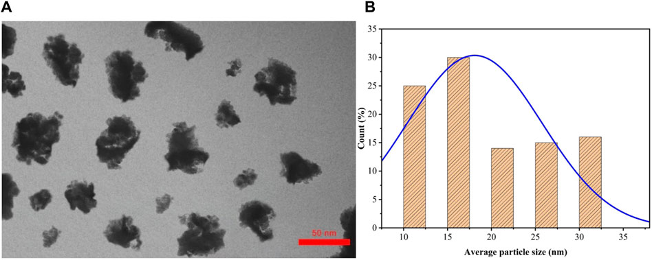
Figure 1. (A) TEM image of the sample preparation. (B) Average particle size of the ferrofluid.
Based on Figure 1B, the average size distribution of Fe3O4 nanoparticles has been investigated for at least 40 particles. In this analysis, it was found that most of the particles have a spherical structure, and according to Figure 1A are formed larger agglomerates. Also, after TEM analysis, according to the histogram diagram in Figure 1B, the average size of the nanoparticles was reported to be 16.2 nm. In this study, the volume fraction of the sample was determined using Equation 1 (Ashjaee et al., 2015):
The bulk density, specific heat, and viscosity values of the nanofluid obtained are expressed as Equations 2–4, respectively:
In these Eq.s,
2.2 Experimental device
The experimental device used in this research is illustrated in Figure 2. This study focuses on investigates the cooling time using a combined cooling method of MF-IJ (Azadi et al., 2023). This method involves two flows: the impingement jet flow and the ferrofluid flow under the impact of a magnetic field. According to Figure 2A, the impingement jet flow hits the top of the heat sink and enters the heat sink through the microchannels located on the top surface. Simultaneously, the ferrofluid flow passes through three channels with circular cross-sections, as depicted in Figure 3B, and enters the heat sink. The setup includes a closed-loop for the ferrofluid flow, which consists of a constant temperature bath and a magnetic field generation system. Additionally, the impingement jet part of the setup comprises a blower fan, flow meter, and nozzle. The overall schematic of the setup can be seen in Figure 2A.
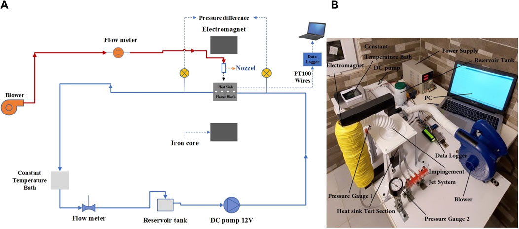
Figure 2. The schematic diagram and components of the experimental apparatus.
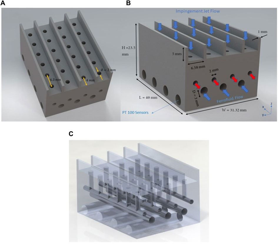
Figure 3. The geometrical model of designed heat sink. (A) Top view. (B) Front view. (C) Transparent view.
2.2.1 Heat sink test section
The heat sink test section includes a heat sink with a structure shown in Figure 3. Additionally, there is a heater block under the heat sink designed to accommodate cartridge heaters. To reduce the impact of thermal conductivity near the test section, the heat sink and heater block are placed inside a plexiglass chamber, except for the top part of the heat sink. This is to minimize the effects of thermal conductivity on the test section. This was done to ensure that heat transfer occurred only between the heater block and the heat sink, without any interference by the ambient environment. In this study, a heat sink made of aluminum 6,061 is utilized. According to Figure 3, the dimensions of the heat sink are 40 mm (L) × 31.32 mm (W) × 23.5 mm (H). The heat sink consists of 3 channels with a diameter of 3 mm, which serve the purpose of transferring the ferrofluid flow and also to transfer the impingement jet flow according to Figure 3A, there are 24 channels on the top of the heat sink with a diameter of 2 mm, and as shown in Figure 3C, they end to 4 channels at the back and front of the heatsink.
Based on Figure 3B, to measure the base temperature of the heat sink, four holes with a diameter of 4.12 mm and a depth of 25 mm were made to install four PT100 temperature sensors in the wall of the heat sink and near its bottom wall. All four temperature sensors were calibrated before the experiment, and their uncertainty value was calculated to be 0.21°C. Moreover, two temperature sensors were installed at the inlet and outlet of the heat sink to measure the nanofluid temperature at the inlet and outlet. For producing a constant heat flux from the downward of the heat sink, a heater block made from aluminum 6,061 with measurements of 40 mm (L) × 31.32 mm (W) × 20 mm (H) was used that the heater block and the heat sink are shown in Figure 4. In this investigation, two cartridge heaters were positioned inside the aluminum heater block. For this purpose, according to Figure 4, two holes with a diameter of 6.48 mm were created inside the heater block.
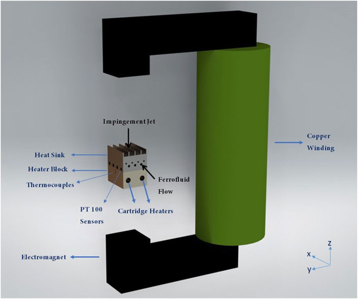
Figure 4. Schematic of the heat sink and heating block in the air gap of the electromagnet.
Also, as depicted in Figure 4, two holes with a diameter of 1 mm and a depth of 15 mm are drilled in the upper part of the heater block to measure the amount of heat flux added under the heat sink by thermocouples. Moreover, as shown in Figure 2B, an ABS (Acrylonitrile Butadiene Styrene) stand was used to hold the jet nozzle, heat sink, and heater block set in the space of the electromagnet device. The ABS stand was chosen because it has low thermal conductivity and non-magnetic nature. It should be mentioned that in this experimental research, thermal grease was used to enhance the heat conduction between the interface of the heater block and the heat sink.
2.2.2 Nanofluid flow circulation device
In this study, a ferrofluid (Fe3O4/water) flows in a closed-loop system from a reservoir tank using a 12V DC pump, model R385, with a flow rate of 3 lit/min, and manufactured by REES52, is powered by a power supply as depicted in Figures 2A, B. Table 1 shows the thermophysical properties of the nanoparticles and the base fluid (water). Additionally, a calibrated flow meter with accuracy of ±2% was used to measure the volumetric flow rate of the nanofluid flowing through the loop. The DC power supply voltage was altered to control the flow rate. Considering that the temperature of the ferrofluid rises after each pass through the heat sink channels, a digital constant temperature bath, as shown in Figure 2, was used in this experimental study for controlling the temperature of the ferrofluid flow.
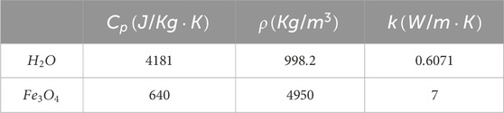
Table 1. Thermophysical properties of the base fluid (water) and nanoparticles (Bezaatpour et al, 2019).
2.2.3 Impingement jet flow device
In this experimental study, a blower fan with an impingement jet inlet temperature of 298 K according to Ref. (Li H. Y. et al., 2005), and the following specifications was used: maximum air volume of 10 m3/min, rated power of 2100 W, and speed of 16,000 rpm. Additionally, a digital flow meter, the cdi 5,200, with a flow rate range of 100 cfm was used to measure the air flow rate, and a converging nozzle with a diameter of 18 mm was utilized to generate a jet flow on the heat sink, as depicted in Figure 2. Also, an ABS confining plate was used for confine the impingement jet and to install the jet device, heater block and heat sink at the center of the electromagnet. The space among top of the heat sink and the nozzle is set as 15 mm and in the jet inlet, a K-type thermocouple was used to measure the jet inlet temperature. It should also be mentioned that the nozzle was positioned in such a way that the center of the heat sink.
2.2.4 Magnetic field production apparatus
In this study, an electromagnetic device shown in Figure 4 is used to create a uniform magnetic field. Due to the high magnetic susceptibility of the ferrite core, it was used in the basic material of the electromagnet device. Additionally, the electromagnet device had a height of 350 mm and a coil diameter of 1.5 mm. As well, the coil is wrapped around the ferrite core, and its total electrical resistance is 14 Ω. To place the heat sink experiment part, there is 190 mm of free space between the tips of the ferrite core. Furthermore, by using a DC power supply and adjusting the current voltage to ranges of 0–5 A and voltage to ranges of 0–24V, the magnetic flux density was controlled within the range of 0–1,000 G. As shown in Figure 4, the magnetic field is applied in the Z direction. According to Ref. (Ashjaee et al., 2015), it is assumed that the magnetic field remains constant under these conditions in the middle of the air gap and the installation site of the heat sink test section. Moreover, in this experimental study, during the experiment the intensity of the magnetic field was measured using a HT 208 digital Gauss meter that had an error within 2%.
2.2.5 Pressure drop measurement throughout the ferrofluid channels
Two Dust Spares model pressure gauges made in England were used to measure the pressure drop at the inlet and outlet of the ferrofluid channels manifold in the heat sink, as shown in Figure 2B. The operational range of these pressure gauges is 0–500 Pa, and they have been calibrated by the manufacturer to have an accuracy of ±1.5%.
3 Data processing
In this section, the Equations used in data processing are provided. As mentioned in section 2.2.1, a heater block and two cartridge heaters have been used for heat generation. Additionally, Equation 6 has been used to compute the heat flux produced by the heater block.
Where, kal is the thermal conductivity of the aluminum heater block, and Tu and Tl denotes the temperatures of the upper and lower thermocouples, respectively. In addition, d indicates the distance between the lower and upper thermocouples. Furthermore, in this study, Equation 7 has been used to calculate the h(x) inside the ferrofluid channels:
Where, Tm (x) and TS (x) are the bulk fluid temperatures and surface temperatures of the heat sink, respectively. According to Figure 3B, four holes were created on the flank of the heat sink to install four PT100 temperature sensors. TS (x) values have been obtained at positions of x = 5, 15, 25, and 35 mm along the length of the heat sink, which are relative to time. Moreover, Tm (x) values were determined based on the energy balance using Equation 8 (Ashjaee et al., 2015).
In Equation 8, Tmi is the inlet temperature of the ferrofluid, q is the total heat flow, L is the heat sink length and
Where,
4 Uncertainty analysis
Uncertainty estimation involves considering various factors, including instrument errors, and calibration errors. These factors contribute to the overall uncertainty associated with a measurement. Measurement errors in quantities like heat flux or temperature can lead to uncertainty in experimental data. Table 2 presents the measurement uncertainties in this experimental research. According to Equation 6, the uncertainty of the heat flux is obtained by Equation 10:
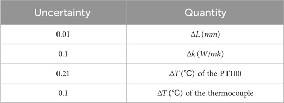
Table 2. Uncertainty of the measured parameters.
In addition, to calculate the uncertainty of the h, as demonstrated by Equation 7, the following relationship is obtained (Ashjaee et al., 2015):
As reported in Ref. (Holman, 2012), the uncertainty of the thermal conductivity is also calculated in a similar manner. In addition, the average uncertainty of the h has been determined to be 8.4% using Equation 11.
5 Data logging of the temperature
In this experimental investigation, four holes were provided in the heat sink body to embed four PT100 sensors. Additionally, two holes were drilled on the heater block to install thermocouple sensors, as shown in Figure 4. To facilitate the measurement and recording of temperatures, six electronic circuits were employed to trigger the PT100 and thermocouple sensors. These sensors were connected to an Arduino board. Each circuit was integrated with a 120 Ω resistance to generate a voltage difference, with a current of 20 mA passing through each circuit. The fluctuation in temperature on the PT100 and thermocouple sensors resulted in corresponding changes in the voltage passing through the circuits. This allowed the heat sink temperature to be recorded using RAM, while simultaneously displaying and recording the information on a PC. Additionally, an LCD was utilized to display the data values, as depicted in Figure 2. Throughout the study, data were recorded at regular intervals of every 2 s.
6 Results and discussion
6.1 Heat transfer experiments in the MF-IJ
In this experimental study, the main goal is to investigate the cooling time of a cooling heat sink using the MF-IJ combined method. Also, ferrofluid flow and air impingement jet flow cross through the channels simultaneously. For this intention, the ferrofluid were entered into the heat sink in three states of inlet temperature of 293, 296 and 298 K and as well, the inlet temperature of the impingement jet of 298 K, where a steady heat flux of 54,000 W/m2 is simultaneously applied of the base surface of the heat sink. The ferrofluid volume fraction is 3% and the Reynolds number (Re) of the ferrofluid in the laminar flow range has been prepared for seven different Re values: 250, 400, 500, 600, 700, 800, and 900. Moreover, the mass flow rate of the air impingement jet produced by the blower have been considered 0.05, 0.1, 0.15 and 0.2 kg/s for this experimental study.
To investigate impact of the uniform magnetic field on cooling time of the heat sink surface temperature in the case of using the combined MF-IJ cooling method, five magnetic field values of 200, 400, 600, 800 and 1,000 were applied. Also, to obtain the h, the surface temperature of the heat sink has been measured in four different locations with the same distance at 5, 15, 25, and 35 mm along the lengths of the heat sink.
To ensure the experimental setup is functioning properly, the outcomes of the current work were compared to the empirical outcomes of Ashjaee et al. (2015). This comparison was done using the heat sink geometry from Ref (Ashjaee et al., 2015). under the flow of DI-water and without the magnetic field and impingement jet flow and also, under the magnetic field of 600 G and without applying the impingement jet flow, have been investigated according to Figures 5A, B.
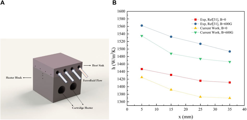
Figure 5. Validation of this experimental study compared with the experimental study of Ashjaee et al. (2015). (A) Schematic of the heat sink and heater block of Ref. (Ashjaee et al., 2015). (B) Variation of the h along the heat sink length.
As is evident from Figure 5B, the maximum variation between the current work and the experimental results is 2.8% for the state of B = 0 and also about 3% for the state of B = 600G. Therefore, the experimental results of Ashjaee et al. are in good agreement with the outcomes of this experimental research.
6.2 Comparison of improvement heat transfer
In this investigation, the essential aim is to determine the cooling time of the combined MF-IJ system. As a result, all tests were conducted with the heat sink surface temperature initially set at an average temperature of 321 K. This temperature was measured by PT100 sensors that were installed on the heat sink, as shown in Figure 4, and it remained consistent for each test. Additionally, considering the heat sink’s geometry and the test conditions, the experiments were performed for up to 80 s in each mode. As shown in Figure 6, the cooling time of the heat sink surface temperature is depicted at x = 0.005 m with utilizing the MF-IJ, MF and IJ cooling methods. It can be seen that if the MF-IJ cooling method is used under Re = 600,
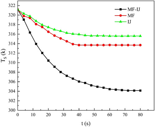
Figure 6. The TS changes over time in different methods for a ferrofluid inlet temperature of 293 K, Re = 600, ∅ = 3%, and a mass flow rate of the impingement jet of 0.1 kg/s.
The temperature difference between the surface and internal areas of the heat sink must equilibrate, necessitating more time for the surface temperature to stabilize. Consequently, as illustrated in Figures 7, 9, the MF-IJ method enhances heat dissipation from the heat sink and decreases the surface temperature due to the increased heat transfer coefficient.
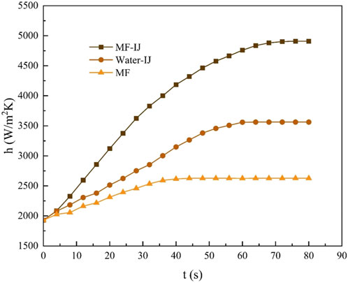
Figure 7. Variations of the h against time at x = 0.005 m, under the conditions of Re = 600, ∅ = 3%, B = 800 G, impingement jet inlet temperature of 298 K, ferrofluid inlet temperature of 293k and mass flow rate of impingement jet of 0.1 kg/s for different methods.
Furthermore, according to Figure 6, the drastic reduction in temperature seen when employing both magnetic field and impingement jet cooling techniques, as opposed to using them individually for cooling and dissipating heat from the heat sink, can be credited to the collaborative effects of these methods. When the magnetic field and impingement jet work simultaneously, they synergistically enhance heat transfer from the surface of the heat sink to the surroundings. The impingement jet boosts convective heat transfer by directing a swift fluid stream onto the heat sink surface, effectively carrying away heat. On the other hand, the presence of a magnetic field influences the behavior of nanoparticles in the nanofluid, resulting in improved heat transfer characteristics. The magnetic field can induce particle alignment or motion, disrupting the formation of thermal boundary layers and promoting even heat distribution throughout the fluid. Combining these techniques results in a more effective heat dissipation process, enabling the heat sink to maintain a lower temperature than when using only the impingement jet or magnetic field methods alone.
The temperature changes on the heat sink surface against time are depicted in Figure 8 for three different ferrofluid inlet temperatures of 293, 296, and 298 K using the MF-IJ method. Figure 8 demonstrates how the TS changes as the inlet temperature of the ferrofluid flow decreases. The steady state results for various investigations of this study are summarized in Table 3. As expected, when the inlet temperature of the ferrofluid reductions, due to the gain in temperature gradient, the TS also reductions over time.
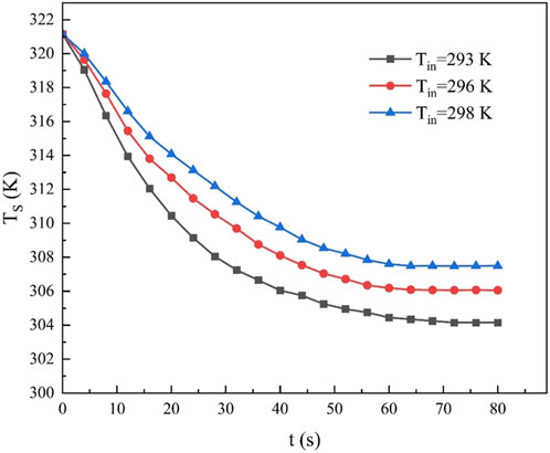
Figure 8. Variations of the TS at x = 0.005 m in response to changes the ferrofluid inlet temperature against time, under the conditions of Re = 600, ∅ = 3%, mass flow rate of the impingement jet of 0.1 kg/s, and impingement jet inlet temperature of 298 K by using the MF-IJ method.
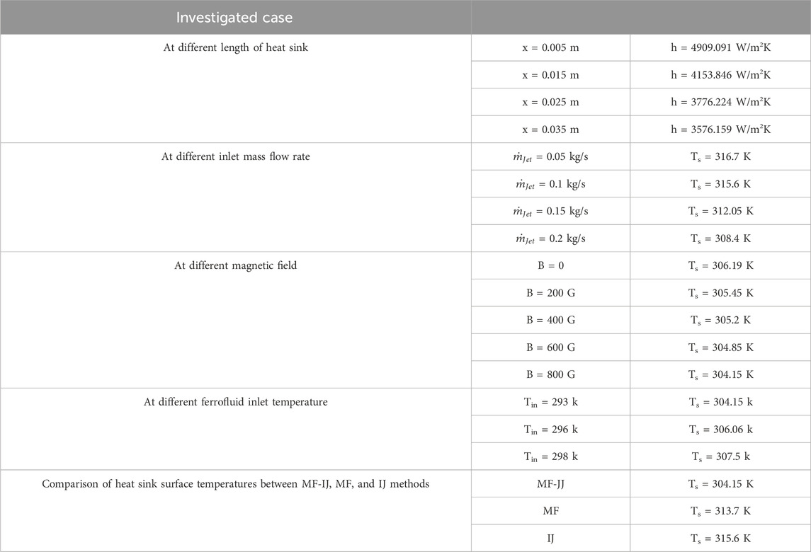
Table 3. Steady state results in different cases.
It is worth noting that in three different ferrofluid inlet temperatures, the TS eventually reaches a steady-state temperature after approximately 70 s. This indicates that the MF-IJ system under these conditions after 70 s reaches a thermal equilibrium.
Interestingly, the temperature of the heat sink surface experiences the most significant changes until reaching 45 s. Beyond this point, the temperature variations become less, suggesting that the MF-IJ system has stabilized. This observation can be attributed to the time required for the heat sink to effectively dissipate the heat by simultaneously affecting the ferrofluid flow and the air impingement jet.
Furthermore, these findings highlight the importance of controlling the inlet temperature of the ferrofluid flow for efficient thermal management. By adjusting the inlet temperature of the ferrofluid, it is possible to regulate the TS and ensure optimal cooling performance.
The variations of the h along the heat sink length against time are presented in Figure 9. It is observed that as the heat sink length increases, the rate of increase in the heat transfer coefficient gradually decreases. This can be attributed to the decrease in the temperature gradient between the ferrofluid and the wall of the heat sink channels. Furthermore, up to 50 s, the changes in the h are very intense, and after 70 s, these values become steady. The steady-state values of the h at lengths of 0.005, 0.015, 0.025, and 0.035 m are determined as 4909.091, 4153.846, 3776.224, and 3576.159 W/m2K, respectively.
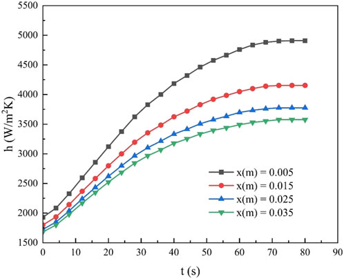
Figure 9. Variations of the h along the heat sink length against time, under the conditions of Re = 600, B = 800 G, ∅ = 3%, impingement jet inlet temperature of 298 K, ferrofluid inlet temperature of 293k, and mass flow rate of the impingement jet of 0.1 kg/s by using the MF-IJ method.
For compare the cooling time of all three cooling methods, namely, the MF-IJ, MF and Water-IJ methods the values of the h against time to reach a steady heat transfer coefficient are depicted in Figure 7. As is evident, the steady heat transfer coefficient values for the methods of MF-IJ, Water-IJ, and MF have been obtained 4909.091, 3562.59, and 2627.73 W/m2K respectively, at the length of x = 0.005 m. It can also be seen that the use of the MF-IJ method in this provided heat sink, compared to the Water-IJ and MF methods, can increase the maximum h by 27.4% and 46.4%, respectively. As mentioned earlier, the combination of magnetic field and impingement jet methods improves the heat transfer process from the heat sink’s surface to its surroundings more effectively than other methods. The results presented in Figure 7 demonstrate that the heat transfer coefficient steadily increases from 0 to 70 s, and then become constant at 4909.091 W/m2K.
The impingement jet’s mass flow rate can affect the temperature of the heat sink surface over time, as demonstrated in Figure 10. It can be seen that the TS decreases when the impingement jet’s mass flow rate increases. This is because, with an increase in the mass flow rate, the temperature gradient increases. Therefore, the h is also improved. Furthermore, this reduction in the temperature of the heat sink surface is more intense up to 30 s, and after approximately 45 s, the temperature of the heat sink surface reaches a steady state. Additionally, the steady values of the TS have been obtained for the MF-IJ method in the mass flow rates of 0.05, 0.1, 0.15, and 0.2 kg/s, which were 316.7, 315.6, 312.05, and 308.4 K respectively.
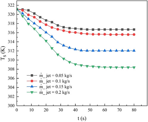
Figure 10. Variations of the TS against time at x = 0.005 m for different mass flow rates, under the conditions of Re = 600, ∅ = 3%, B = 800 G, impingement jet inlet temperature of 298 K, ferrofluid inlet temperature of 293 k by using the MF-IJ method.
The impact of magnetic field intensity on the surface temperature of the heat sink over time is depicted in Figure 11 of this research.
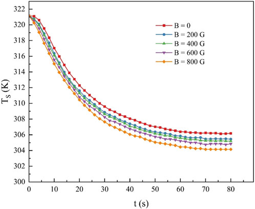
Figure 11. Impact of magnetic field on variation of the TS against time at x = 0.005 m, under the conditions of Re = 600, ∅ = 3%, impingement jet inlet temperature of 298 K, ferrofluid inlet temperature of 293k and mass flow rate of impingement jet of 0.1 kg/s by using the MF-IJ method.
It is observed with rise in magnetic field, the temperature of the heat sink surface gradually decreases over time. For example, for magnetic fields of 200 G and 800 G, the temperature of the heat sink surface in a steady state has reached 305.45 K and 304.15 K, respectively.
Additionally, these temperature changes exhibit the most significant variations within the first 45 s. As mentioned before, in this experimental study, the initial TS was considered to be 321 K for each experiment. This means that before starting each experiment, the TS was raised to 321 K using a heater block installed beneath it, and then each test was performed.
The efficiency values are calculated with Equation 12 from Ref. (Ashjaee et al., 2015). Where,
According to Figure 12, the efficiency values against time are shown for each of the methods MF-IJ, Water-IJ, and MF. It is observable that the changes in efficiency with respect to time for each of the mentioned methods decrease from 75, 65 and 45 s onwards, respectively. In addition, the constant efficiency values for the MF-IJ, Water-IJ and MF methods for the designed heat sink were obtained as 1.175, 1.05, and 0.95, respectively.
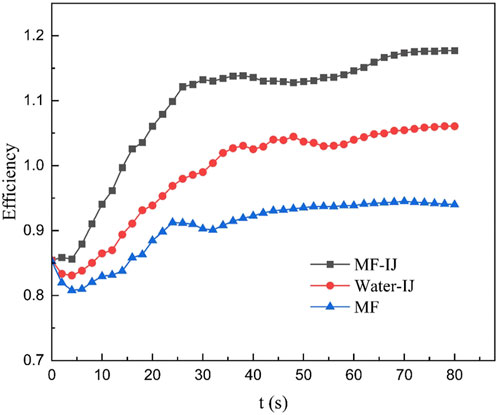
Figure 12. Variation of efficiency against time for different methods.
For the MF-IJ method, the variations of the Nu against time in different lengths of the heat sink are depicted in Figure 13. As shown, the values of the Nu increase with time, and this increase is more intense until 45 s. It is also found that the variations in the Nu at the beginning of the channel (x = 0.005 m) are greater than other lengths. The Nusselt numbers at x = 0.005, 0.015, 0.025, and 0.035 m have reached steady state as 32, 27, 24.7, and 23.3, respectively. Due to the high flow velocity at the beginning of the channel, this phenomenon occurs, which enhances convective heat transfer. The temperature gradient is also steeper at the inlet, resulting in more significant variations in the Nu.
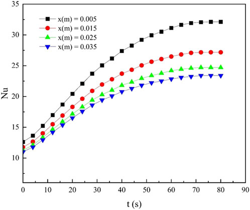
Figure 13. Variations of the Nu in the channels of ferrofluid against time for different lengths of the heat sink under the conditions of Re = 600, ∅ = 3%, impingement jet inlet temperature of 298 K, ferrofluid inlet temperature of 293k and mass flow rate of impingement jet of 0.1 kg/s.
6.3 Pressure drop experiments in the channels of ferrofluid
In this experimental research, the pressure drop along the ferrofluid channels was measured using pressure gauges at the inlet and outlet of the heat sink, as shown in Figure 2. According to Figure 14, the effect of magnetic field variations on the pressure drop in the ferrofluid channels within the heat sink is shown under the following conditions: a volume fraction of 3%, an impingement jet inlet temperature of 298 K, and a ferrofluid inlet temperature of 293 K.
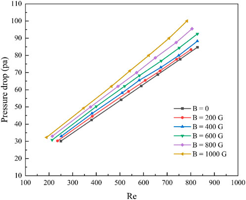
Figure 14. Investigation of variations in magnetic field intensities on the pressure drop along the channels of the ferrofluid for the MF-IJ method.
As shown, the pressure drops increases with rise in the magnetic field and the Reynolds number inside the ferrofluid channels. When an external magnetic field is existence, the magnetic particles in the base fluid align in a chain-like pattern in line with the field’s direction and therefore, the ferrofluid’s viscosity increases due to this alignment (Li Q. et al., 2005). Thus, even though there is an improvement in heat transfer with magnetic field, it also results in a higher pressure drop (Ashjaee et al., 2015). Furthermore, it can be concluded that with an increase in the magnetic field, a higher pressure drop at the same Reynolds number can be observed.
7 Conclusion
The current study experimentally investigated the combined effects of using an impingement jet (IJ) on the surface of a heat sink with air flow channels and passing ferrofluid under the influence of a magnetic fields (MF) to reduce cooling time and improve heat transfer. The h, TS, pressure drop throughout the heat sink, and the variation of efficiency against time have been calculated for the MF-IJ, Water-IJ, and MF methods. Finally, the aforementioned findings have been obtained:
• It was observed that when using the MF-IJ, only MF, and only IJ methods for the proposed heat sink under the conditions of Re = 600,
• The TS at x = 0.005 m was reduced with changes in the ferrofluid inlet temperature to 293, 296, and 298 K against time.
• During the heat sink length, the rate of increase in h gradually decreases. After 70 s, the steady-state values of convective heat transfer coefficient at lengths of 0.005, 0.015, 0.025, and 0.035 m are obtained as 4909.091, 4153.846, 3776.224, and 3576.159 W/m2K, respectively.
• By comparing the cooling times of three methods, MF-IJ, Water-IJ, and MF, it is evident that using the MF-IJ method in the heat sink being studied can increase the maximum convective heat transfer coefficient by 27.4% and 46.4% in comparison to the Water-IJ and MF methods, respectively.
• By increasing the mass flow rate of the impingement jet to values of 0.005, 0.1, 0.15, and 0.2 kg/s, the TS under cooling by the MF-IJ method at x = 0.005 m decreased by 316.7, 315.6, 312.05, and 308.4 K, respectively.
• As the B increased, the TS slowly decreased over time.
• The maximum efficiency of the combined MF-IJ method has improved by approximately 10.6% compared to the Water-IJ method and by approximately 19.1% compared to the MF method in this novel heat sink.
Based on the results obtained in this study, the use of the MF-IJ method can decrease cooling time compared to the Water-IJ and MF methods, while also enhancing heat dissipation from the heat sinks.
Data availability statement
The original contributions presented in the study are included in the article/supplementary material, further inquiries can be directed to the corresponding author.
Author contributions
SA: Investigation, Validation, Visualization, Writing–original draft. AA: Data curation, Investigation, Project administration, Writing–review and editing. AV: Investigation, Methodology, Supervision, Writing–review and editing. HAh: Investigation, Methodology, Supervision, Writing–original draft. HAf: Investigation, Methodology, Supervision, Validation, Writing–original draft.
Funding
The author(s) declare that no financial support was received for the research, authorship, and/or publication of this article.
Conflict of interest
The authors declare that the research was conducted in the absence of any commercial or financial relationships that could be construed as a potential conflict of interest.
Publisher’s note
All claims expressed in this article are solely those of the authors and do not necessarily represent those of their affiliated organizations, or those of the publisher, the editors and the reviewers. Any product that may be evaluated in this article, or claim that may be made by its manufacturer, is not guaranteed or endorsed by the publisher.
References
Abdolahipour, S. (2023). Effects of low and high frequency actuation on aerodynamic performance of a supercritical airfoil. Front. Mech. Eng. 9, 1290074. doi:10.3389/fmech.2023.1290074
Abdolahipour, S., Mani, M., and Shams Taleghani, A. (2022a). Pressure improvement on a supercritical high-lift wing using simple and modulated pulse jet vortex generator. Flow. Turbul. Combust. 109 (1), 65–100. doi:10.1007/s10494-022-00327-9
Abdolahipour, S., Mani, M., and Shams Taleghani, A. (2022b). Experimental investigation of flow control on a high-lift wing using modulated pulse jet vortex generator. J. Aerosp. Eng. 35 (5), 05022001. doi:10.1061/(asce)as.1943-5525.0001463
Abdolahipour, S., Mani, M., and Taleghani, A. S. (2021). Parametric study of a frequency-modulated pulse jet by measurements of flow characteristics. Phys. Scr. 96 (12), 125012. doi:10.1088/1402-4896/ac2bdf
Ahmadi, R., Hosseini, H. R. M., Masoudi, A., Omid, H., Namivandi-Zangeneh, R., Ahmadi, M., et al. (2013). Effect of concentration on hydrodynamic size of magnetite-based ferrofluid as a potential MRI contrast agent. Colloids Surfaces A Physicochem. Eng. Asp. 424, 113–117. doi:10.1016/j.colsurfa.2012.11.069
Ahmadi, R., Malek, M., Hosseini, H. R. M., Shokrgozar, M. A., Oghabian, M. A., Masoudi, A., et al. (2011). Ultrasonic-assisted synthesis of magnetite based MRI contrast agent using cysteine as the biocapping coating. Mater. Chem. Phys. 131 (1-2), 170–177. doi:10.1016/j.matchemphys.2011.04.083
Andrade, Â. L., Fabris, J. D., Ardisson, J. D., Valente, M. A., and Ferreira, J. M. (2012). Effect of tetramethylammonium hydroxide on nucleation, surface modification and growth of magnetic nanoparticles. J. Nanomater. 2012 (1), 1–10. doi:10.1155/2012/454759
Ashjaee, M., Goharkhah, M., Khadem, L. A., and Ahmadi, R. (2015). Effect of magnetic field on the forced convection heat transfer and pressure drop of a magnetic nanofluid in a miniature heat sink. Heat. Mass Transf. 51, 953–964. doi:10.1007/s00231-014-1467-1
Azadi, S., Abjadi, A., Vahdat Azad, A., Ahmadi Danesh Ashtiani, H., and Afshar, H. (2023). Enhancement of heat transfer in heat sink under the effect of a magnetic field and an impingement jet. Front. Mech. Eng. 9, 1266729. doi:10.3389/fmech.2023.1266729
Baz, F. B., Elshenawy, E. A., El-Agouz, S. A., El-Samadony, Y. A. F., and Marzouk, S. A. (2024). Experimental study on air impinging jet for effective cooling of multiple protruding heat sources. Int. J. Therm. Sci. 196, 108707. doi:10.1016/j.ijthermalsci.2023.108707
Bezaatpour, M., and Goharkhah, M. (2019). Effect of magnetic field on the hydrodynamic and heat transfer of magnetite ferrofluid flow in a porous fin heat sink. J. Magn. Magn. Mater. 476, 506–515. doi:10.1016/j.jmmm.2019.01.028
Bhaduri, S., Ray, A., De, A., and Sugarno, M. I. (2024). Flow control in a confined supersonic cavity flow using subcavity. Front. Mech. Eng. 10, 1378433. doi:10.3389/fmech.2024.1378433
Cui, H. C., Shi, C. Y., Yu, M. J., Zhang, Z. K., Liu, Z. C., and Liu, W. (2023). Optimal parameter design of a slot jet impingement/microchannel heat sink base on multi-objective optimization algorithm. Appl. Therm. Eng. 227, 120452. doi:10.1016/j.applthermaleng.2023.120452
Cui, H. C., Xie, J. H., Zhao, R. Z., Wang, M. Z., Liu, Z. C., and Liu, W. (2022). Thermal-hydraulic performance analysis of a hybrid micro pin–fin, jet impingement heat sink with non-uniform heat flow. Appl. Therm. Eng. 208, 118201. doi:10.1016/j.applthermaleng.2022.118201
Do, K. H., Kim, T. H., and Kim, S. J. (2010). Analytical and experimental investigations on fluid flow and thermal characteristics of a plate-fin heat sink subject to a uniformly impinging jet. Int. J. Heat. mass Transf. 53 (9-10), 2318–2323. doi:10.1016/j.ijheatmasstransfer.2009.12.049
Fateh, S., Shafii, M. B., Najafi, M., and Aghanajafi, C. (2024). Experimental investigation on the ferrofluid flow in a horizontal mini channel under the constant magnetic field using PIV. Powder Technol. 431, 119090. doi:10.1016/j.powtec.2023.119090
Gan, T., Ming, T., Fang, W., Liu, Y., Miao, L., Ren, K., et al. (2020). Heat transfer enhancement of a microchannel heat sink with the combination of impinging jets, dimples, and side outlets. J. Therm. Anal. Calorim. 141, 45–56. doi:10.1007/s10973-019-08754-z
Ghofrani, A., Dibaei, M. H., Sima, A. H., and Shafii, M. B. (2013). Experimental investigation on laminar forced convection heat transfer of ferrofluids under an alternating magnetic field. Exp. Therm. Fluid Sci. 49, 193–200. doi:10.1016/j.expthermflusci.2013.04.018
Hai, T., Sharma, K., Marjan, R. K., Farhang, B., Mahmoud, M. H., Fouad, H., et al. (2023). Numerical analysis of the magnetic field impact on hydrothermal characteristics of a microchannel heatsink with Fe3O4 ferrofluid and various pin-fin shapes. J. Magn. Magn. Mater. 585, 171102. doi:10.1016/j.jmmm.2023.171102
Hashemi, S. M. H., Fazeli, S. A., Zirakzadeh, H., and Ashjaee, M. (2012). Study of heat transfer enhancement in a nanofluid-cooled miniature heat sink. Int. Commun. Heat. Mass Transf. 39 (6), 877–884. doi:10.1016/j.icheatmasstransfer.2012.04.005
Huang, L., Yeom, T., Simon, T., and Cui, T. (2021). An experimental and numerical study on heat transfer enhancement of a heat sink fin by synthetic jet impingement. Heat. Mass Transf. 57, 583–593. doi:10.1007/s00231-020-02974-y
Hwang, S. G., Garud, K. S., Seo, J. H., and Lee, M. Y. (2022). Heat flow characteristics of ferrofluid in magnetic field patterns for electric Vehicle power electronics cooling. Symmetry 14 (5), 1063. doi:10.3390/sym14051063
Kempers, R., Colenbrander, J., Tan, W., Chen, R., and Robinson, A. J. (2020). Experimental characterization of a hybrid impinging microjet-microchannel heat sink fabricated using high-volume metal additive manufacturing. Int. J. Thermofluids 5, 100029. doi:10.1016/j.ijft.2020.100029
Kotb, A., Askar, H., and Saad, H. (2023). On the impingement of heat transfer using swirled air jets. Front. Mech. Eng. 9, 1120985. doi:10.3389/fmech.2023.1120985
Li, H. Y., Chao, S. M., and Tsai, G. L. (2005b). Thermal performance measurement of heat sinks with confined impinging jet by infrared thermography. Int. J. Heat. Mass Transf. 48 (25-26), 5386–5394. doi:10.1016/j.ijheatmasstransfer.2005.07.007
Li, Q., and Xuan, Y. (2009). Experimental investigation on heat transfer characteristics of magnetic fluid flow around a fine wire under the influence of an external magnetic field. Exp. Therm. Fluid Sci. 33 (4), 591–596. doi:10.1016/j.expthermflusci.2008.12.003
Li, Q., Xuan, Y., and Wang, J. (2005a). Experimental investigations on transport properties of magnetic fluids. Exp. Therm. Fluid Sci. 30 (2), 109–116. doi:10.1016/j.expthermflusci.2005.03.021
Li, Z., Sun, J., Li, J., Fan, B., Zhong, M., Jiang, N., et al. (2023). Flow and heat transfer performance of array finned channel coupled jet heat sink. Appl. Therm. Eng. 221, 119813. doi:10.1016/j.applthermaleng.2022.119813
Mirzaei, M., Taleghani, A. S., and Shadaram, A. (2012). Experimental study of vortex shedding control using plasma actuator. Appl. Mech. Mater. 186, 75–86. doi:10.4028/www.scientific.net/amm.186.75
Mohammadi, M., and Taleghani, A. S. (2014). Active flow control by dielectric barrier discharge to increase stall angle of a NACA0012 airfoil. Arab. J. Sci. Eng. 39, 2363–2370. doi:10.1007/s13369-013-0772-1
Mostafa, Y. T., El-Dosoky, M. F., Abdelgawad, M., and Hassan, O. (2023). Numerical investigation of a hybrid double layer microchannel heat sink with jet impingement. Int. J. Thermofluids 20, 100465. doi:10.1016/j.ijft.2023.100465
Naphon, P., Wiriyasart, S., Arisariyawong, T., and Nakharintr, L. (2019). ANN, numerical and experimental analysis on the jet impingement nanofluids flow and heat transfer characteristics in the micro-channel heat sink. Int. J. Heat. Mass Transf. 131, 329–340. doi:10.1016/j.ijheatmasstransfer.2018.11.073
Nasif, G., Shinneeb, A. M., and Balachandar, R. (2024). Cooling enhancement for engine parts using jet impingement. Front. Mech. Eng. 10, 1251587. doi:10.3389/fmech.2024.1251587
Noori, M. S., Rahni, M. T., and Taleghani, A. S. (2020b). Effects of contact angle hysteresis on drop manipulation using surface acoustic waves. Theor. Comput. Fluid Dyn. 34, 145–162. doi:10.1007/s00162-020-00516-0
Noori, M. S., Taleghani, A. S., and Rahni, M. T. (2020a). Phenomenological investigation of drop manipulation using surface acoustic waves. Microgravity Sci. Technol. 32, 1147–1158. doi:10.1007/s12217-020-09839-3
Noori, M. S., Taleghani, A. S., and Rahni, M. T. (2021). Surface acoustic waves as control actuator for drop removal from solid surface. Fluid Dyn. Res. 53 (4), 045503. doi:10.1088/1873-7005/ac12af
Rahni, M. T., Taleghani, A. S., Sheikholeslam, M., and Ahmadi, G. (2022). Computational simulation of water removal from a flat plate, using surface acoustic waves. Wave Motion 111, 102867. doi:10.1016/j.wavemoti.2021.102867
Sadighi, S., Afshar, H., Ashtiani, H. A. D., and Jabbari, M. (2023b). MHD flow and conductive heat transfer on a permeable stretching cylinder: benchmark solutions. Case Stud. Therm. Eng. 44, 102886. doi:10.1016/j.csite.2023.102886
Sadighi, S., Afshar, H., Jabbari, M., and Ahmadi Danesh Ashtiani, H. (2022). An analytical approach to entropy production in MHD mixed convection micropolar fluid flow over an inclined porous stretching sheet. Front. Mech. Eng. 8, 900316. doi:10.3389/fmech.2022.900316
Sadighi, S., Afshar, H., Jabbari, M., and Ashtiani, H. A. D. (2023a). Heat and mass transfer for MHD nanofluid flow on a porous stretching sheet with prescribed boundary conditions. Case Stud. Therm. Eng. 49, 103345. doi:10.1016/j.csite.2023.103345
Salehi, A., and Fattahi, A. (2024). A numerical investigation of hydrogen impingement-effusion array jet for a heat sink cooling using solid/porous fins: a thermo-hydrodynamic analysis. Int. J. Hydrogen Energy 52, 381–396. doi:10.1016/j.ijhydene.2023.05.257
Salmasi, A., Shadaram, A., and Taleghani, A. S. (2013). Effect of plasma actuator placement on the airfoil efficiency at poststall angles of attack. IEEE Trans. Plasma Sci. 41 (10), 3079–3085. doi:10.1109/tps.2013.2280612
Sawada, T., Kikura, H., Saito, A., and Tanahashi, T. (1993). Natural convection of a magnetic fluid in concentric horizontal annuli under nonuniform magnetic fields. Exp. Therm. fluid Sci. 7 (3), 212–220. doi:10.1016/0894-1777(93)90004-3
Selvakumar, P., and Suresh, S. (2012). Convective performance of CuO/water nanofluid in an electronic heat sink. Exp. Therm. Fluid Sci. 40, 57–63. doi:10.1016/j.expthermflusci.2012.01.033
Shabi, O. A., Alhazmy, M., Negeed, E. S. R., and Elzoghaly, K. O. (2024). Experimental investigation of shell and helical coiled heat exchanger with Al2O3 nano-fluid with wide range of particle concentration. Front. Mech. Eng. 10, 1386254. doi:10.3389/fmech.2024.1386254
Shahsavar, A., Askari, I. B., Ghodrat, M., Arıcı, M., Nižetić, S., Rehman, T. U., et al. (2023). Experimental investigation of the effect of mechanical vibration and rotating magnetic field on the hydrothermal performance of water-Fe3O4 ferrofluid inside a rifled tube. J. Magn. Magn. Mater. 572, 170586. doi:10.1016/j.jmmm.2023.170586
Shams Taleghani, A., and Sheikholeslam Noori, M. (2022). Numerical investigation of coalescence phenomena, affected by surface acoustic waves. Eur. Phys. J. Plus 137, 975. doi:10.1140/epjp/s13360-022-03175-8
Sunaryono, S., Taufiq, A., Mufti, N., Susanto, H., Putra, E. G. R., Darminto, D., et al. (2018). Contributions of TMAH surfactant on hierarchical structures of PVA/Fe 3 O 4–TMAH Ferrogels by using SAXS instrument. J. Inorg. Organomet. Polym. Mater. 28, 2206–2212. doi:10.1007/s10904-018-0939-z
Suqi, W., Chao, Z., Congxiang, T., and Junyi, Y. (2024). Use of machine learning in predicting heat transfer and entropy generation in a flat plate solar collector with twisted tape turbulator and ferrofluid under the influence of an external uniform magnetic field: a numerical study. J. Magn. Magn. Mater. 590, 171657. doi:10.1016/j.jmmm.2023.171657
Taleghani, A. S., Shadaram, A., and Mirzaei, M. (2012). Effects of duty cycles of the plasma actuators on improvement of pressure distribution above a NLF0414 airfoil. IEEE Trans. Plasma Sci. 40 (5), 1434–1440. doi:10.1109/tps.2012.2187683
Taleghani, A. S., Shadaram, A., Mirzaei, M., and Abdolahipour, S. (2018). Parametric study of a plasma actuator at unsteady actuation by measurements of the induced flow velocity for flow control. J. Braz. Soc. Mech. Sci. Eng. 40, 173–213. doi:10.1007/s40430-018-1120-x
Thakar, S. S., Nambiar, S., Chandavarkar, G. A., and Prabu, S. S. (2021). Investigation of impingement cooling on a heat sink using CFD simulation. Mater. Today Proc. 46, 8753–8760. doi:10.1016/j.matpr.2021.04.066
Wang, J., Kong, H., Xu, Y., and Wu, J. (2019). Experimental investigation of heat transfer and flow characteristics in finned copper foam heat sinks subjected to jet impingement cooling. Appl. energy 241, 433–443. doi:10.1016/j.apenergy.2019.03.040
Wiriyasart, S., Kaewluan, S., and Suksusron, P. (2023). Heat transfer performance of thermoelectric cooling integrated with wavy channel heat sink with different magnetic distances. Heat. Transf. 52 (6), 3936–3952. doi:10.1002/htj.22863
Yakut, R., Yakut, K., Yeşildal, F., and Karabey, A. (2016). Experimental and numerical investigations of impingement air jet for a heat sink. Procedia Eng. 157, 3–12. doi:10.1016/j.proeng.2016.08.331
Yi, L., Yang, S., and Pan, M. (2022). Experimental investigation and parameter analysis of micro-jet impingement heat sink for improved heat transfer performance. Chem. Eng. Processing-Process Intensif. 174, 108867. doi:10.1016/j.cep.2022.108867
Zamzamian, A., Oskouie, S. N., Doosthoseini, A., Joneidi, A., and Pazouki, M. (2011). Experimental investigation of forced convective heat transfer coefficient in nanofluids of Al2O3/EG and CuO/EG in a double pipe and plate heat exchangers under turbulent flow. Exp. Therm. Fluid Sci. 35 (3), 495–502. doi:10.1016/j.expthermflusci.2010.11.013
Zhang, Y., Zhang, P., Chen, L., Chen, S., and Hou, Y. (2023). Numerical study on thermal and hydraulic performance of a stacked-plate jet-impingement/microchannel heat sink. Appl. Therm. Eng. 225, 120134. doi:10.1016/j.applthermaleng.2023.120134
Zhong, J. F., Sedeh, S. N., Lv, Y. P., Arzani, B., and Toghraie, D. (2021). Investigation of Ferro-nanofluid flow within a porous ribbed microchannel heat sink using single-phase and two-phase approaches in the presence of constant magnetic field. Powder Technol. 387, 251–260. doi:10.1016/j.powtec.2021.04.033
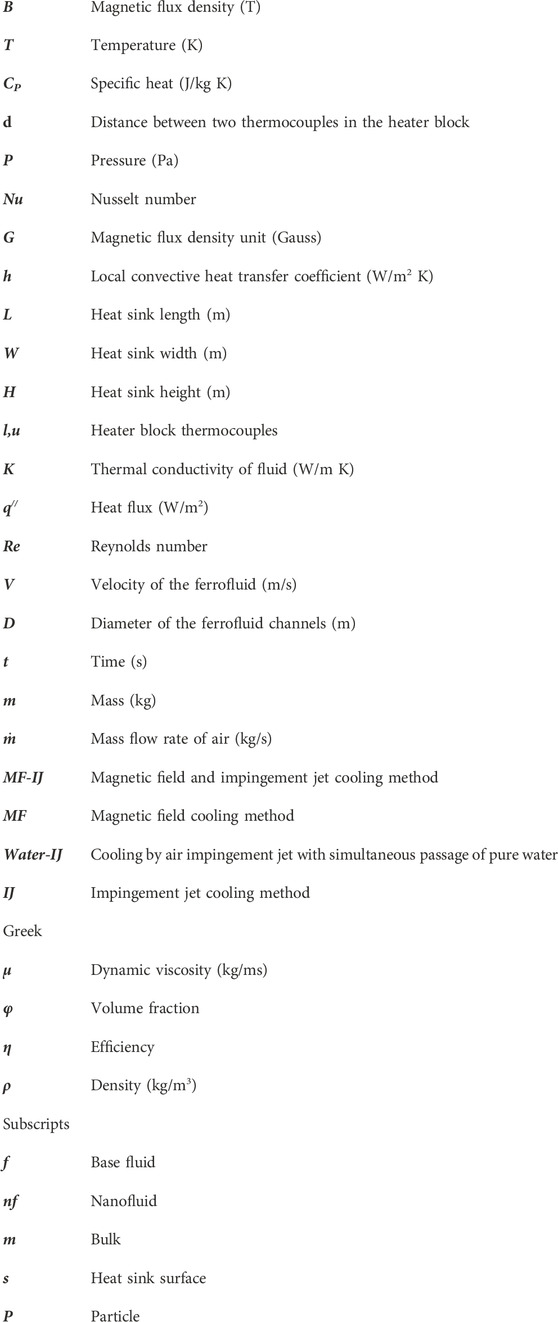
Nomenclature
Keywords: flow control, cooling time, impingement jet, magnetic field, heat sink, ferrofluid, experimental study
Citation: Azadi S, Abjadi A, Vahdat Azad A, Ahmadi Danesh Ashtiani H and Afshar H (2024) Experimental investigation of enhancement heat dissipation in a novel heat sink under simultaneous impact of impingement jet and magnetic field. Front. Mech. Eng. 10:1450972. doi: 10.3389/fmech.2024.1450972
Received: 18 June 2024; Accepted: 30 July 2024;
Published: 13 August 2024.
Edited by:
Mohammad Taeibi Rahni, Sharif University of Technology, IranReviewed by:
Ebrahim Afshari, University of Isfahan, IranArash Shams Taleghani, Ministry of Science, Research and Technology, Iran
Alireza Dehghanisanij, University of Waterloo, Canada
Copyright © 2024 Azadi, Abjadi, Vahdat Azad, Ahmadi Danesh Ashtiani and Afshar. This is an open-access article distributed under the terms of the Creative Commons Attribution License (CC BY). The use, distribution or reproduction in other forums is permitted, provided the original author(s) and the copyright owner(s) are credited and that the original publication in this journal is cited, in accordance with accepted academic practice. No use, distribution or reproduction is permitted which does not comply with these terms.
*Correspondence: Ali Abjadi, YV9hYmphZGlAYXphZC5hYy5pcg==