 Hanul Chun
 Tomoko Hirayama1*
 Naoya Hatano
 Reiko Kuriyama
- 1Graduate School of Engineering, Department of Mechanical Engineering and Science, Kyoto University, Kyoto, Japan
- 2Department of Mechanical Engineering and Physics, Kyoto Institute of Technology, Kyoto, Japan
Grease is used as a lubricant in a wide range of fields, including bearings, because it reduces friction, prevents harmful wear of components, protects against rust and corrosion, and acts as a seal to prevent the invasion of dirt and water. Although most of the research on grease has focused on the environment inside the bearing, there has been little research on the fundamental lubrication mechanism of grease. It is known that thickeners, which keep a complex three-dimensional structure in the grease, have a significant effect on the shear characteristics of grease, and it is assumed that this is due to the orientation of the thickener structure in the shear direction. In this study, the apparent viscosity of grease in a micro-order gap was measured using our original viscometer and compared with the apparent viscosity measured with a submillimeter-order gap rheometer because grease may show different rheological properties compared to conventional measurements. In addition, the dynamic response of viscous resistance that appeared when each grease was subjected to a change in the shear force was quantitatively evaluated using relaxation time. As a result, the apparent viscosity remarkably decreased in a micro-order gap compared to a submillimeter gap, and two types of shear thinning mechanisms were proposed based on the orientation of the thickener: one caused by the narrow gap and the other by the shear force. In addition, the behavior of viscous resistance due to changes in the shear force depended on the type of thickener. It was also confirmed that the relaxation time of each grease correlates with its oil film-forming ability and the entanglement level of the thickener’s structure. Furthermore, the mechanism of the dynamic response was proposed based on the reorientation of thickeners.
1 Introduction
Tribology is one of the academic disciplines in the field of mechanical engineering that studies phenomena and properties related to friction, wear, and lubrication on sliding surfaces, which play an important role in industry and daily life. Understanding the properties of friction and lubrication between sliding surfaces and ensuring their sliding operation with a lower friction coefficient under optimal conditions is critical to improving the efficiency and reliability of mechanical components, resulting in these tribological studies extending the life of machines and reducing maintenance costs even while considering (Bhushan and Ko, 2003; Kandeva et al., 2016; Woydt, 2021; Bukvić et al., 2024).
In the recent trend toward further energy conservation in machinery and equipment, demand for lubricating grease is increasing even more (Akhtar et al., 2016; Gohar and Rahnejat, 2018; Rawat and Harsha, 2019). With the recent trend toward electric vehicles (EVs) in automobiles, there is a stronger need than ever before to reduce friction to meet the growing demand for rolling bearings, and the development of lubricating grease that can achieve lower friction has been recognized as one of the keys to this trend. Compared to lubricating oil, grease has a longer replenishment interval and is less prone to leakage and dispersal (Lugt, 2009; Farfan-Cabrera, 2019; Shah et al., 2021).
Grease is widely used as a lubricant for rolling bearings (Lugt, 2009), and studies have been conducted on the behavior of grease in bearing operation, bearing operating life (Lugt et al., 2023), and frictional resistance (Cousseau et al., 2011) from the viewpoint of grease lubrication. There are churning and channeling, which describe the macroscopic grease lubrication condition in the bearing. On one hand, the churning state is when the grease that has been churned up by the rolling elements flows back into the raceway and is churned up again by the rolling elements (Lugt, 2009). Channeling, on the other hand, is a state in which the grease is kept stirred up by the rolling elements, the amount of grease flowing in the bearing becomes small, and the viscous resistance caused by the grease goes low, making it a preferred lubrication state (Chatra et al., 2020). Numerous studies have been reported for the two states, churning and channeling, in grease lubrication or for the transition process to both states (Cann and Lubrecht, 1999; Cann et al., 2001; Cann, 2007; Lugt, 2009; Gao et al., 2018; Chatra et al., 2020; Chatra et al., 2021; Chatra K R et al., 2022; Obata et al., 2024; Shetty et al., 2024). With the recent development of observation technology, it has become possible to observe the lubrication state inside bearings using X-rays and neutron beams (Noda et al., 2020; Sakai et al., 2021). In addition, various studies have been conducted to analyze and predict the mechanism of grease lubrication in rolling bearings and the film thickness under elastohydrodynamic (EHL) contact (Cann and Lubrecht, 1999; Cann, 2007; Cen and Lugt, 2019; Wu et al., 2022) since rolling bearings are the main application of grease (Cann et al., 2001; Lugt, 2009; Cen and Lugt, 2019; Chatra et al., 2020). However, not many fundamental studies have attempted to elucidate the basic lubrication mechanism of grease away from the concept that is used in rolling bearings (Mansot et al., 1989; Chapkov et al., 2007; Saatchi et al., 2017; Camousseigt et al., 2023).
Typical greases consist of thickener fibers with a three-dimensional structure and base oil (Lugt, 2016). The first consideration in the use of grease on mechanical sliding surfaces is its rheological properties. The relationship between thickeners and grease lubrication properties has been reported. Suetsugu et al. (2013) elucidated that the network density of the thickener in grease is related to its storage modulus. Delgado et al. investigated how the microstructure of the lithium complex soap impacts the tribological properties of greases, the effect of cooling rate during grease production on fiber length and flexibility, and how thickener size influences the structural and fiber strength of thickeners. They also examined the relationship between local viscoelastic properties and thickener structure at the submicron scale, finding that viscosity increased with higher thickener concentrations. Still, the thickness, length, and structural stiffness of the thickener fibers remained constant (Delgado et al., 2005). There is also a precedent for using FE-SEM, FT-IR, and XPS to investigate how the microstructure of the thickener affects the rheological and tribological properties of the grease (Onoda et al., 2021). In addition, the relationship between thickener structure and its shear strength was studied by changing the shear rate in lithium and urea greases, and the effect of thickener chemical structure on grease oil film formation has been studied (Mubashshir and Shaukat, 2019).
However, the specific correlation between the microstructure of the thickener and the rheological property of the grease is still unclear. Hotten proposed a model in which the thickener structure in the grease is oriented or broken down at a high shear rate. Still, the oriented thickener structure partially returns to its original structure when the sliding operation stops and returns to a static state (Hotten, 1955). Moreover, several other theoretical models have been proposed in the past, but they have not yet been established as useful models for actual grease lubrication analysis (Bristeau et al., 1980; Abdali et al., 1992; Radulescu et al., 2003). Furthermore, most studies on grease have been limited to ball bearings, the main application of grease (Hutton, 1975; Cann and Lubrecht, 1999; Cann, 2007; Lugt, 2009; Cousseau et al., 2011; Maksimova et al., 2018; Cen and Lugt, 2019; Hirayama et al., 2020; Noda et al., 2020; Chatra et al., 2021; Sakai et al., 2021; Lugt et al., 2023), and few fundamental studies have focused on the underlying fundamental lubrication mechanisms and properties of grease under shear.
Originally, it is well known that grease shows viscosity reduction characteristics in response to the shear rate. Generally, parallel plate or cone plate viscometers are used to obtain the viscosity characteristics of grease in response to the shear rate. However, in tribological situations, the gap between two sliding surfaces is on the order of the nanometer to the micrometer at most, which is much narrower than the gap realized by such typical viscometers. Considering this, the shear properties of oil films containing oiliness additives in micrometer gaps were investigated. It has been proposed that the absolute size of the gap, not the shear rate, determines whether interfacial sliding occurs, and it has been reported that the shear force decreases as the gap narrows (Hirayama et al., 2020). On the other hand, until now, no studies have evaluated grease properties in few-micron gaps, and the behavior of the grease in gaps narrower than thickener fibers has remained unknown. Since the lubrication environment is expected to become more severe with the miniaturization of future machine elements, research on grease in micrometer gaps is essential.
In this study, the parallel disk viscometer developed in the previous study (Hirayama et al., 2020) was used to investigate the shear characteristics of grease in a micrometer gap. First, the sliding gap was estimated using the base oil to measure the gap length by the vertical load. The apparent viscosity of the grease was then measured according to various gaps in micrometer order and compared to the apparent viscosity measured by a conventional viscometer with a submillimeter gap. In addition, the response force of the grease sandwiched in the micrometer gap to step changes in the shear rate as the input was investigated, and its dynamic viscosity characteristic behavior was finally discussed.
2 Parallel-disk viscometer
2.1 Viscometer configuration and operation
The overall configuration of the parallel-disk viscometer used in this study is described in the paper (Hirayama et al., 2020). The sliding part of the viscometer consists of an upper specimen and a lower disk, as shown in Figure 1, and the viscometer’s main dimensions are shown in Table 1. The upper specimen is made of stainless steel (SUS440C), and the lower disk is made of borosilicate crown glass (BK7). A surface-restricted aerostatic bearing is located at the center of the upper specimen. An air supply hole is made in the center of the upper specimen, through which compressed air flows to form the aerostatic bearing with the lower disk. The aerostatic bearing face is grooved by etching as the surface restriction that changes the pressure distribution when the gap between the upper specimen and the lower disk changes and can keep the gap constant, owing to the generation of bearing stiffness. The details of the pressure distribution that occurs in aerostatic bearings are explained in the previous paper (Hirayama et al., 2020). The compressed air flows from the center of the upper specimen into the aerostatic bearing area. It is exhausted out of the side of the upper specimen through the deep groove between the aerostatic bearing area and the outer ring area. The lubricating oil or sample grease is sandwiched only in the outer ring area between the upper specimen and the lower disk. The lower disk holder, which does not rotate but is softly supported by the leaf springs, can maintain a parallel between the upper specimen and the lower disk due to the tilting stiffness of the aerostatic bearing. When the upper specimen is rotated by a motor using a belt, an arm attached to the lower disk holder pushes a load cell in the rotating direction, which can measure the shear force of the sample oil or grease in the narrow gap. The rotational force measured by the load cell for the rotational direction pushed by the arm is represented as
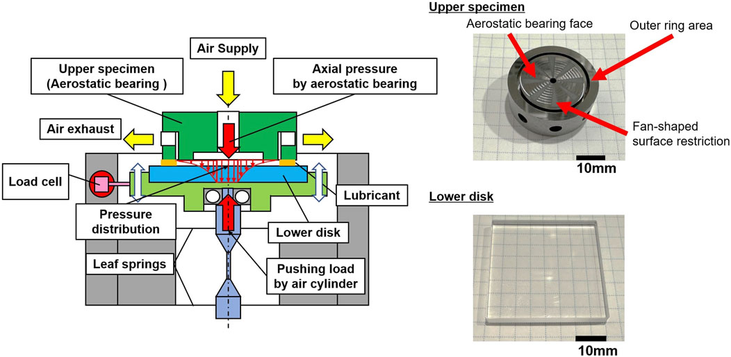
Figure 1. Drawing of the sliding part of the parallel-disk viscometer and the upper specimen and lower disk.
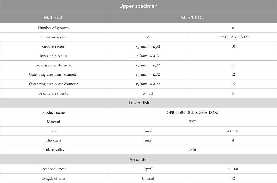
Table 1. Dimensions of the main parts of the parallel-disk viscometer.
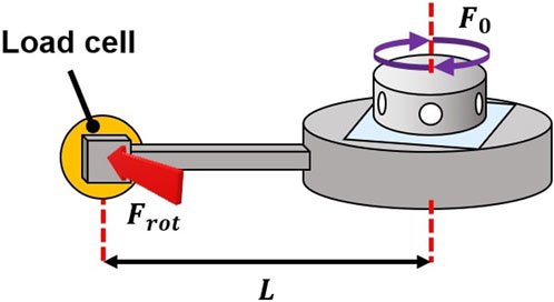
Figure 2. Measurement of rotational force
The gap length is changed by varying the pushing load using an air cylinder assembled below the lower disk holder. The pushing load is then measured by a load cell for the vertical direction set between the lower disk holder and the load cell.
2.2 Estimation method for gap length
Here, the method for estimating the gap length in the parallel-disk viscometer is described. When the upper specimen is rotated, the sample oil or grease that is sandwiched between the upper specimen and the lower disk generates the rotational force
where r and θ are arbitrary radius and angle, respectively, η is the known viscosity of the lubricating oil,
So, the relationship between the rotational torque
On the other hand, considering the relationship between the rotational force measured by the load cell located a distance
Therefore, the shear force
To estimate the gap length h, by differentiating Eq. 3 with respect to the angular velocity
Since the inner and outer radii of the upper specimen,
2.3 Gap length estimation using a base oil
To estimate the gap length h by the pushing force of the air cylinder, three kinds of alkyl diphenyl ether (ADE)-type base oils with different known viscosities were selected. The physical properties of the base oils used are shown in Table 2. The number in the name of each base oil corresponds to the kinematic viscosity at 40°C. Note that ADE is a typical base oil often used as a component of sample greases. The room temperature was maintained at 22°C–23°C in this study.
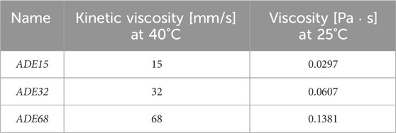
Table 2. Kinetic viscosity and viscosity of base oils.
As an example, Figure 3 shows the rotational force
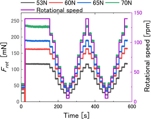
Figure 3. Rotational force for the base oil measured at each rotational speed and pushing load.
To determine the gap length using the pushing force of the air cylinder, the same experiment shown in Figure 3 was conducted with the three base oils listed in Table 2, and
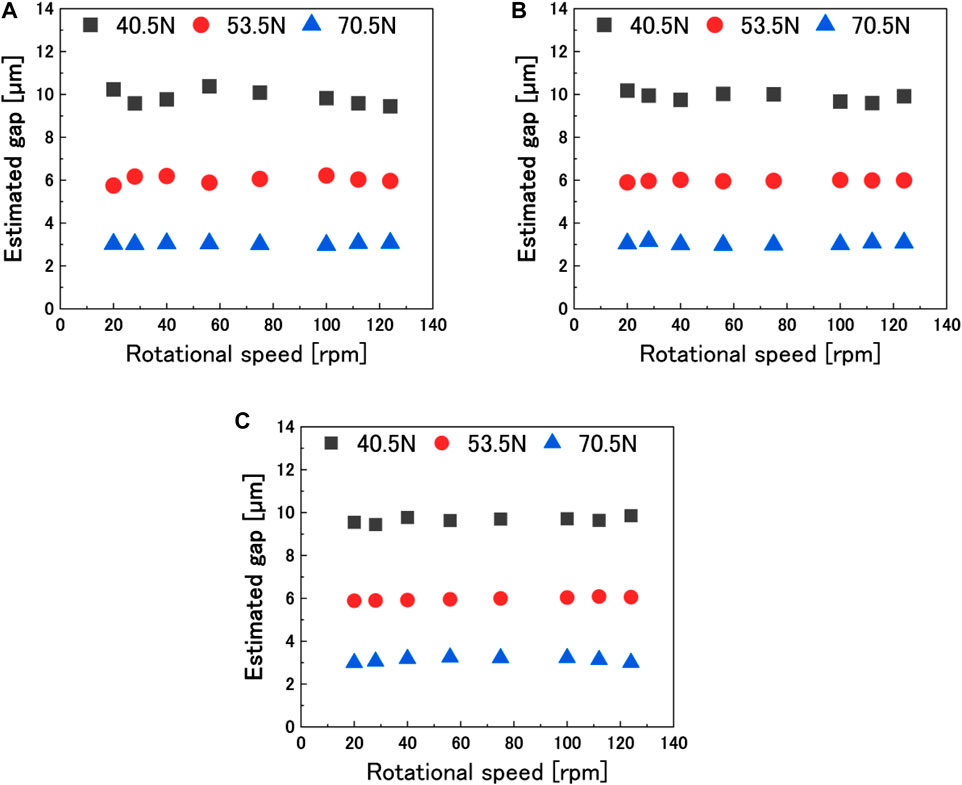
Figure 4. Estimated gap using the base oil under several pushing loads: (A) ADE15, (B) ADE32, and (C) ADE68.
2.4 Calculation of the apparent viscosity of grease
After the gap length h was estimated using the lubricating base oil, the sample grease was sandwiched instead of the lubricating base oil in the outer ring area, and its shear force was measured at each rotational speed. Since the experiment in Section 2.3 has proven that the gap length is constant regardless of the sample viscosity and the rotational speed of the upper specimen and that the gap length h was estimated at 10, 6, and 3 µm under the pushing forces of 40.5, 53.5, and 70.5 N, respectively, the estimated gap length was newly defined as the known value
The viscosity η calculated using Eq. 8 is called the apparent viscosity in this study. The equivalent shear rate
3 Apparent viscosities of greases in the narrow gap at the steady shear rate condition
3.1 Test greases
In this experiment, typical urea grease and lithium grease were used as test greases. Their compositions and physical properties are shown in Table 3. The chemical structures and scanning electron microscopic (SEM) images are shown in Figure 5. Eventually, these samples are denoted as “urea” and “lithium.” The lithium grease used in this experiment is thickened using lithium stearate, which has a chain-like end group, while the urea grease is thickened using aromatic urea, which has a cyclic end group. The difference in the chemical structure of each thickener shown in Figure 5 indicates that the urea grease has a lumpy mesh structure, whereas the lithium grease is intertwined in a fiber-like structure, as shown in the SEM image.
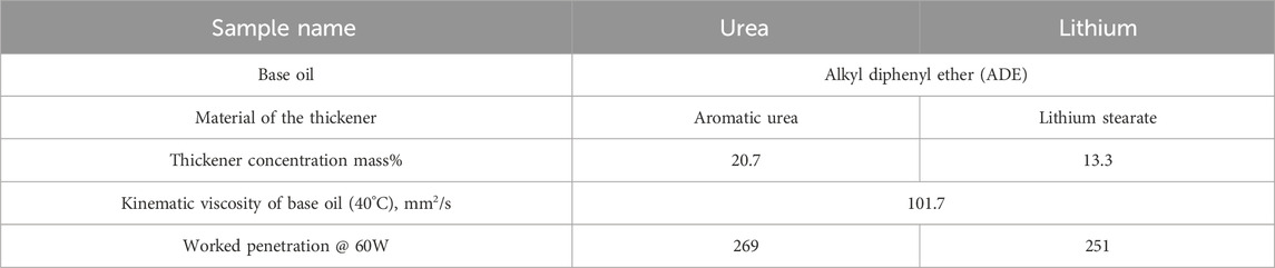
Table 3. Composition and properties of sample greases (Komiya et al., 2019).
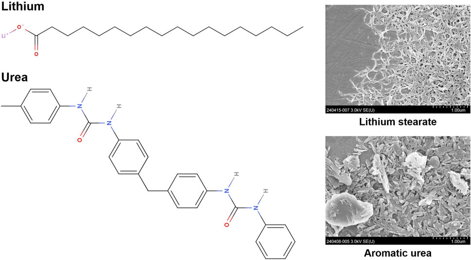
Figure 5. Chemical structure of the thickener and SEM images of the thickener.
3.2 Experimental procedure
In this study, the viscosity of sample greases was measured at a steady shear rate using a parallel-disk viscometer with a narrow gap. Then, the gap length between the upper specimen and the lower disk was varied by changing the pushing load, and the relationship between the pushing load and the gap length is determined in Section 2.3. The experimental procedure is described as follows:
1. Start rotating the upper specimen at 40 rpm for 20 s to distribute grease over the sliding surface.
2. Start rotating the upper specimen at 160 rpm, the maximum speed, for 600 s. This operation allows the grease to be homogeneously placed in the gap and the stable shear force to be measured.
3. Measure the shear force while decelerating every 60 s from the maximum speed of 160 rpm to a minimum speed of 20 rpm. The set of rotational speeds was [160, 140, 120, 100, 80, 60, 40, and 20] rpm.
4. Measure the shear force while accelerating every 60 s from 20 rpm to the maximum speed of 160 rpm after the rotational speed reaches 20 rpm. The set of rotational speeds was the same as shown in the previous step but in reverse order.
5. Stop the rotation and finish the experiment.
3.3 Experimental results and discussion
Figure 6 shows the rotational force
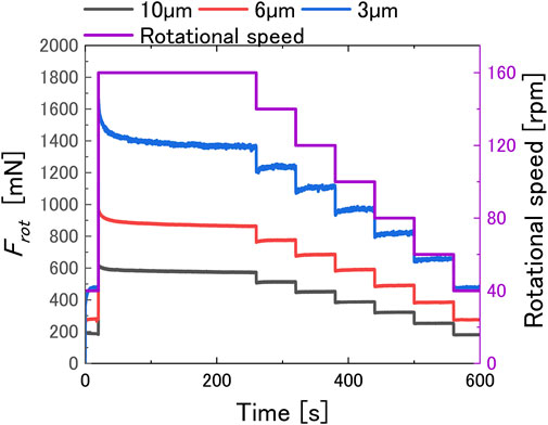
Figure 6. Rotational force of the urea grease measured at each rotational speed and gap.
Figure 7 shows the apparent viscosity of each grease at gaps 10, 6, and 3 μm, where the horizontal axis is the shear rate, which is calculated using Eq. 9. In the figure, the viscosity measured using a commercial rheometer with parallel plates (Physcia MCR 301, Anton Paar) is also shown. In the measurement, the gap lengths between the plates were set at 150, 350, and 700 μm, and the shear rate was calculated at the outer diameter of the plate at ϕ25 mm. The temperature setting was set at 23°C to be consistent with the room temperature in the laboratory. Figure 7 shows that the apparent viscosity of the grease decreased with the increasing shear rate regardless of the grease type and gap length, so-called ‘shear thinning’ behavior. However, the apparent viscosities of both greases measured in the narrow gap were lower than those measured in the sufficiently wide gap. Furthermore, this trend was more pronounced for narrower gap lengths. Shear properties at this narrow gap are described in more detail.
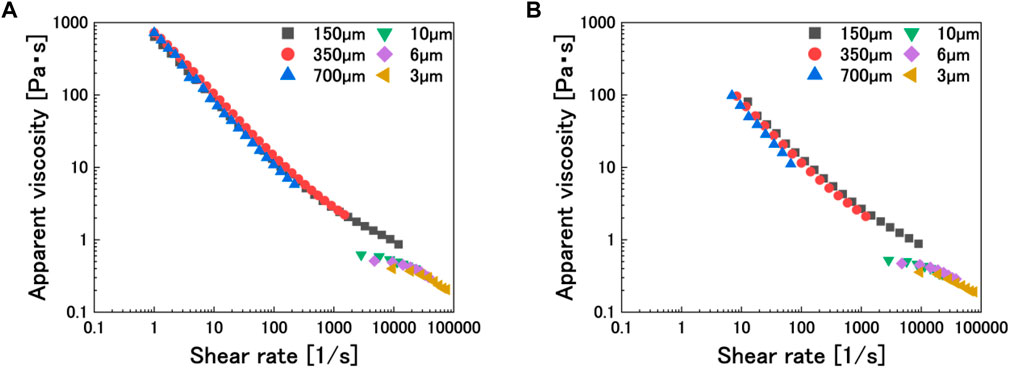
Figure 7. Apparent viscosity of grease with several gap lengths: (A) urea grease and (B) lithium grease.
At a shear rate of approximately 10,000
There have been many studies on the orientation of grease thickeners from the past, but most of them are due to shear forces. For example, Hokao et al. investigated the morphology of shear-induced structural changes in the thickener and reported that the higher the shear force, the clearer the orientation of the thickener fibers (Hokao et al., 2019). However, no study has been found when the gap length is equivalent to the size of grease thickeners, and it can be said that this study could propose a novel mechanism for the viscosity behaviors of greases in an environment close to the actual tribological field.
4 Viscoelastic behaviors of greases in narrow gaps with changing speed conditions
4.1 Experimental procedure
As mentioned earlier, when the rotational speed changed,
1. Start rotating the upper specimen at 160 rpm, the maximum speed, for 600 s. This operation allows the grease to be homogeneously placed in the gap and ensures stable measurement of shear force.
2. Set the pushing load to 50, 60, and 68 N, respectively, and rotate the motor at 40 rpm for 5 min. Then, change the rotational speed instantaneously to 160 rpm as a step input and maintain the speed for 5 min. Measure the shear force continuously during this procedure.
3. Stop the rotation and finish the experiment.
4.2 Experimental results
The experimental results for
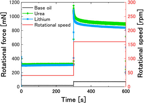
Figure 8. Relaxation behaviors of base oil, urea grease, and lithium grease for the step input of rotational speed.
For example, in stress relaxation tests, when the initial stress is
The relaxation time
The relationship between the relaxation time
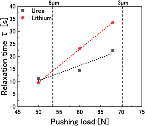
Figure 9. 90% relaxation time of each grease according to the pushing load.
4.3 Discussion
First, we need to address the possibility that the viscosity of the sample has changed due to the high shear rate of the sample in the narrow gap. However, because the oil film is airtight and thin, it is difficult to control or measure temperature directly. Of course, heat is generated by sliding, but the heat generated is transferred quickly to the upper specimen and the lower disk due to their large heat capacities; therefore, the viscosity of the sample oil barely changes. The evidence suggests that Figure 3 shows that
As shown in Figure 9, the relaxation time of the grease increased linearly with increasing the pushing load, i.e., with decreasing gap length. In the experiment, the rotation speed of the upper specimen was changed as a step input from 40 to 160 rpm, and the rate of change of the shear rate in the gap is also greater when the gap is narrower. Therefore, it takes time for the grease to orient itself in response to the change in the shear rate, so the relaxation time was longer when the gap was narrower.
On the other hand, Figure 9 shows that the relaxation time increased with the decreasing gap for the lithium stearate grease compared to the aromatic urea grease. This means that the urea grease stabilized faster when subjected to the same change in the shear rate. Since this difference could be attributed to the type of thickener, it was discussed in connection with the ‘grease film-forming ability’ of each grease. The ‘grease film-forming ability’ is a technical term used to describe the ease of forming a grease film to separate the contact surfaces and the strength of the formed grease film; the higher the grease film-forming ability, the easier it is for the contact surfaces to remain non-contact. Komiya et al. (2019) used five types of greases with different thickeners, including the aromatic urea grease and lithium stearate grease used in our study, and examined the grease film-forming ability of each grease using a two-cylinder tester. They measured the contact ratio between the two cylinders using an electric potential difference method when grease was supplied between the two cylinders and rotated in a pure rolling condition. The value calculated from the contact ratio was called the ‘grease film-forming rate,’ with 0% defined as a complete contact state, 100% as a complete non-contact state, and values in between as partial contact states. As a result, with the lithium grease, the grease film-forming rate between the two cylinders gradually increased as the rotation speed increased, reaching a maximum of 80%, but the grease film-forming rate remained at almost 80% even at the highest rotation speed. On the other hand, the urea grease reached a grease film-forming rate of 80% immediately after the start of the test, even at low speeds, and maintained 100% grease film formation at higher speeds. The tendency of the relaxation time of the lithium grease to be longer than that of the urea grease, as shown in Figure 9, is considered to correlate with this grease film-forming ability. When the shear rate changes, the aromatic urea grease immediately forms a stable grease film due to the entanglement of aromatic rings in the thickener, whereas the lithium stearate grease takes longer to form a stable grease film due to less entanglement of thickeners. The longer relaxation time of the lithium grease, as shown in Figure 9, is considered to be due to this same phenomenon occurring in the grease film.
In addition, it can be explained by the structural complexity of the thickener. Xu et al. investigated the structure strength, structural rearrangement speed, and recoverability of several lithium greases. As a result, the higher the entanglement level of the thickener, the higher the structure strength, the slower the rearrangement speed, and the lower the recoverability of the grease (Xu et al., 2018). Considering urea and lithium used in this experiment, lithium, which has a long mesh structure, seems to have a higher entanglement level than urea, which has independent clumps of short fibers, as shown in Figure 5. It is believed that the high entanglement required more time for the thickener to reorient, resulting in a longer relaxation time, similar to the experiment conducted by Xu et al.
As described in Section 4.1, the time-dependent curves that appear when the rotational speed is changed are attributed to the thickener microstructure, which requires time for reorientation in response to changes in the shear rate. The mechanism of the characteristic curves that appear in Figures 6, 8 during deceleration and acceleration will be discussed, concerning the degree of orientation of the thickener. Consider the case of deceleration, i.e., when the shear force exerted on the grease is reduced. Before deceleration, the thickener is considered to be strongly oriented in the shear direction due to the high shear force. When the shear rate is rapidly decreased from this state, the thickener is subjected to a low shear force while maintaining a high degree of orientation, so
5 Conclusion
In this study, the apparent viscosity and the shear force behavior of urea and lithium greases in the micrometer-order gap were investigated using the parallel-disk viscometer. The conclusions drawn from this study are as follows:
The apparent viscosity of the urea grease and lithium grease decreased as the gap became narrower under shear rates below 10,000
When the grease was subjected to shear change, a characteristic curve appeared. The curve was caused by the fact that it takes time for the thickener structure to reorient in response to the shear force that changed, which showed the reorientation mechanism of the thickener during acceleration and deceleration. The time requirement was quantitatively evaluated in terms of relaxation time, and it was shown that the relaxation time increases as the gap narrows, and the degree of increase depends on the thickener and is correlated with the oil film-forming ability of the grease and the entanglement level of the thickener.
Data availability statement
The original contributions presented in the study are included in the article/Supplementary Material; further inquiries can be directed to the corresponding author.
Author contributions
HC: data curation, formal analysis, methodology, writing–original draft, writing–review and editing, investigation, and visualization. TH: conceptualization, software, supervision, and writing–review and editing. NY: writing–review and editing, supervision, and validation. NH: software and writing–review and editing. KT: resources and writing–review and editing. RK: resources and writing–review and editing.
Funding
The authors declare that no financial support was received for the research, authorship, and/or publication of this article.
Acknowledgments
The authors would like to thank all the people who assisted in the conduct of this study. The base oil and grease samples were provided by MORESCO Corporation and Nippon Grease Co., Ltd., respectively. They would also like to thank Mr. Heegwan Son for his helpful advice on building a data analysis program.
Conflict of interest
The authors declare that the research was conducted in the absence of any commercial or financial relationships that could be construed as a potential conflict of interest.
Publisher’s note
All claims expressed in this article are solely those of the authors and do not necessarily represent those of their affiliated organizations, or those of the publisher, the editors, and the reviewers. Any product that may be evaluated in this article, or claim that may be made by its manufacturer, is not guaranteed or endorsed by the publisher.
References
Abdali, S. S., Mitsoulis, E., and Markatos, N. C. (1992). Entry and exit flows of Bingham fluids. J. Rheol. (N Y N Y) 36, 389–407. doi:10.1122/1.550350
Akhtar, K., Khalid, H., Ul Haq, I., and Malik, A. (2016). Improvement in tribological properties of lubricating grease with quartz-enriched rice husk ash. Tribol. Int. 93, 58–62. doi:10.1016/j.triboint.2015.09.015
Bhushan, B., and Ko, P. (2003). Introduction to tribology. Appl. Mech. Rev. 56, B6–B7. doi:10.1115/1.1523360
Bristeau, M. O., Glowinski, R., Mantel, B., Periaux, J., Perrier, P., and Pironneau, O. (1980). “A finite element approximation of Navier-Stokes equations for incompressible viscous fluids. Iterative methods of solution,” in Approximation methods for Navier-Stokes problems. Editor R. Rautmann (Berlin, Heidelberg: Springer Berlin Heidelberg), 78–128. doi:10.1007/BFb0086902
Bukvić, M., Gajević, S., Skulić, A., Savić, S., Ašonja, A., and Stojanović, B. (2024). Tribological application of nanocomposite additives in industrial oils. Lubricants 12, 6. doi:10.3390/lubricants12010006
Camousseigt, L., Galfré, A., Couenne, F., Oumahi, C., Muller, S., and Tayakout-Fayolle, M. (2023). Oil-bleeding dynamic model to predict permeability characteristics of lubricating grease. Tribol. Int. 183, 108418. doi:10.1016/J.TRIBOINT.2023.108418
Cann, P., and Lubrecht, A. A. (1999). An analysis of the mechanisms of grease lubrication in rolling element bearings. Lubr. Sci. 11, 227–245. doi:10.1002/ls.3010110303
Cann, P. M. (2007). Grease lubrication of rolling element bearings — role of the grease thickener. Lubr. Sci. 19, 183–196. doi:10.1002/ls.39
Cann, P. M., Doner, J. P., Webster, M. N., and Wikstrom, V. (2001). Grease degradation in rolling element bearings. Tribol. Trans. 44, 399–404. doi:10.1080/10402000108982473
Cen, H., and Lugt, P. M. (2019). Film thickness in a grease lubricated ball bearing. Tribol. Int. 134, 26–35. doi:10.1016/J.TRIBOINT.2019.01.032
Chapkov, A. D., Bair, S., Cann, P., and Lubrecht, A. A. (2007). Film thickness in point contacts under generalized Newtonian EHL conditions: numerical and experimental analysis. Tribol. Int. 40, 1474–1478. doi:10.1016/J.TRIBOINT.2007.01.002
Chatra, K. R. S., and Lugt, P. M. (2020). Channeling behavior of lubricating greases in rolling bearings: identification and characterization. Tribol. Int. 143, 106061. doi:10.1016/j.triboint.2019.106061
Chatra, K. R. S., and Lugt, P. M. (2021). The process of churning in a grease lubricated rolling bearing: channeling and clearing. Tribol. Int. 153, 106661. doi:10.1016/J.TRIBOINT.2020.106661
Chatra, K. R. S., Osara, J. A., and Lugt, P. M. (2022). Impact of grease churning on grease leakage, oil bleeding and grease rheology. Tribol. Int. 176, 107926. doi:10.1016/j.triboint.2022.107926
Cousseau, T., Graça, B., Campos, A., and Seabra, J. (2011). Friction torque in grease lubricated thrust ball bearings. Tribol. Int. 44, 523–531. doi:10.1016/j.triboint.2010.06.013
Delgado, M. A., Sánchez, M. C., Valencia, C., Franco, J. M., and Gallegos, C. (2005). Relationship among microstructure, rheology and processing of a lithium lubricating grease. Chem. Eng. Res. Des. 83, 1085–1092. doi:10.1205/cherd.04311
Farfan-Cabrera, L. I. (2019). Tribology of electric vehicles: a review of critical components, current state and future improvement trends. Tribol. Int. 138, 473–486. doi:10.1016/j.triboint.2019.06.029
Gao, W., Nelias, D., Boisson, N., and Lyu, Y. (2018). Model formulation of churning losses in cylindrical roller bearings based on numerical simulation. Tribol. Int. 121, 420–434. doi:10.1016/j.triboint.2018.02.003
Hirayama, T., Shibata, S., Harada, T., Hashimoto, Y., and Yamashita, N. (2020). Shear property of oil film containing oiliness additive in narrow gap measured with newly-developed parallel-disk viscometer supported by aerostatic bearing. Lubr. Sci. 32, 46–57. doi:10.1002/ls.1485
Hokao, M., Sonoda, K., and Sugimura, J. (2019). The relationship between structural change of thickeners and rheological properties on lubricating grease. J. Jpn. Soc. Tribol. 64, 42–54. doi:10.18914/tribologist.18-00017
Hutton, J. F. (1975). “The influence of flow elasticity on the bearing performance of lubricating greases,” in Proc JSLE-ASLE International Lubrication Conference, ASLE, July 1, 1976, 707–714.
Kandeva, M., Karastoyanov, D., Assenova, E., Jakimovska, K., Simeonov, S., and Vencl, A. (2016). The influence of the valena metal-plating additive on tribotechnical characteristics of the Steel–Bronze tribological system. J. Frict. Wear 37, 187–190. doi:10.3103/S1068366616020082
Komiya, H., Geshi, Y., Yaotani, N., Hirayama, T., Matsuoka, T., and Sakamoto, H. (2019). Effects of thickener on oil film formation of lubricating grease: mechanism of grease film formation with adhesion/deposition of thickener on friction surface. J. Jpn. Soc. Tribol. 64, 33–41. doi:10.18914/tribologist.18-00012
Lugt, P. M. (2009). A review on grease lubrication in rolling bearings. Tribol. Trans. 52, 470–480. doi:10.1080/10402000802687940
Lugt, P. M. (2016). Modern advancements in lubricating grease technology. Tribol. Int. 97, 467–477. doi:10.1016/j.triboint.2016.01.045
Lugt, P. M., Holgerson, M., and Reinholdsson, F. (2023). Impact of oxidation on grease life in rolling bearings. Tribol. Int. 188, 108785. doi:10.1016/j.triboint.2023.108785
Maksimova, Y. M., Shakhmatova, A. S., Ilyin, S. O., Pakhmanova, O. A., Lyadov, A. S., Antonov, S. V., et al. (2018). Rheological and tribological properties of lubricating greases based on esters and polyurea thickeners. Pet. Chem. 58, 1064–1069. doi:10.1134/S0965544118120071
Mansot, J. L., Terech, P., and Martin, J. M. (1989). Structural investigation of lubricating greases. Colloids Surfaces 39, 321–333. doi:10.1016/0166-6622(89)80283-5
Mubashshir, M., and Shaukat, A. (2019). The role of grease composition and rheology in elastohydrodynamic lubrication. Tribol. Lett. 67, 104. doi:10.1007/s11249-019-1218-z
Noda, T., Shibasaki, K., Miyata, S., and Taniguchi, M. (2020). X-ray CT imaging of grease behavior in ball bearing and numerical validation of multi-phase flows simulation. Tribol. Online 15, 36–44. doi:10.2474/trol.15.36
Obata, T., Fujiwara, H., Itoigawa, F., and Maegawa, S. (2024). Effect of grease viscosity on channeling properties of ball bearings. Lubricants 12, 13. doi:10.3390/lubricants12010013
Onoda, E., Nogi, T., and Moriuchi, T. (2021). Observation technologies for grease thickener. J. Jpn. Soc. Tribol. 66, 676–681. doi:10.18914/tribologist.66.09_676
Radulescu, A. V., Bonneau, D., and Hajjam, M. (2003). A theoretical study of two-dimensional grease flow in regions with discontinuities. Lubr. Sci. 15, 163–171. doi:10.1002/ls.3010150206
Rawat, S. S., and Harsha, A. P. (2019). “Current and future trends in grease lubrication,” in Automotive tribology. Editors J. K. Katiyar, S. Bhattacharya, V. K. Patel, and V. Kumar (Singapore: Springer Singapore), 147–182. doi:10.1007/978-981-15-0434-1_9
Saatchi, A., Shiller, P. J., Eghtesadi, S. A., Liu, T., and Doll, G. L. (2017). A fundamental study of oil release mechanism in soap and non-soap thickened greases. Tribol. Int. 110, 333–340. doi:10.1016/J.TRIBOINT.2017.02.004
Sakai, K., Ayame, Y., Iwanami, Y., Kimura, N., and Matsumoto, Y. (2021). Observation of grease fluidity in a ball bearing using neutron imaging technology. Tribol. Online 16, 146–150. doi:10.2474/TROL.16.146
Shah, R., Tung, S., Chen, R., and Miller, R. (2021). Grease performance requirements and future perspectives for electric and hybrid vehicle applications. Lubricants 9, 40. doi:10.3390/lubricants9040040
Shetty, P., Meijer, R. J., Osara, J. A., Pasaribu, R., and Lugt, P. M. (2024). Effect of grease filling on the film thickness in deep-groove ball bearings. Tribol. Trans. 67, 62–69. doi:10.1080/10402004.2023.2282632
Suetsugu, Y., Sekiguchi, H., Nakanishi, Y., Fujinami, Y., and Ohno, T. (2013). Basic study of grease rheology and correlation with grease properties. Tribol. Online 8, 83–89. doi:10.2474/trol.8.83
Woydt, M. (2021). The importance of tribology for reducing CO2 emissions and for sustainability. Wear 474-475, 203768–204475. doi:10.1016/j.wear.2021.203768
Wu, M., Han, X., Tao, Y., and Pei, J. (2022). A mixed EHL analysis method for grease and formulas for film thickness and asperity load. Tribol. Lett. 70, 128. doi:10.1007/s11249-022-01666-4
Keywords: grease, micrometer gap, apparent viscosity, thickener structure, orientation
Citation: Chun H, Hirayama T, Yamashita N, Hatano N, Tatsumi K and Kuriyama R (2024) Shear properties and dynamic responses of greases in a micrometer-order gap. Front. Mech. Eng 10:1420852. doi: 10.3389/fmech.2024.1420852
Received: 21 April 2024; Accepted: 18 June 2024;
Published: 15 July 2024.
Edited by:
Alessandro Ruggiero, University of Salerno, ItalyReviewed by:
Slavica Miladinovic, University of Kragujevac, SerbiaMladen Radojković, University of Priština in Kosovska Mitrovica, Serbia
Copyright © 2024 Chun, Hirayama, Yamashita, Hatano, Tatsumi and Kuriyama. This is an open-access article distributed under the terms of the Creative Commons Attribution License (CC BY). The use, distribution or reproduction in other forums is permitted, provided the original author(s) and the copyright owner(s) are credited and that the original publication in this journal is cited, in accordance with accepted academic practice. No use, distribution or reproduction is permitted which does not comply with these terms.
*Correspondence: Tomoko Hirayama, dG9tb2tvQG1lLmt5b3RvLXUuYWMuanA=