 Guosheng Wang
94% of researchers rate our articles as excellent or good
Learn more about the work of our research integrity team to safeguard the quality of each article we publish.
Find out more
ORIGINAL RESEARCH article
Front. Mech. Eng., 07 January 2025
Sec. Engine and Automotive Engineering
Volume 10 - 2024 | https://doi.org/10.3389/fmech.2024.1411552
Introduction: Technological innovation is the key to ensuring the safety performance of new energy vehicles, which is crucial for ensuring the safety performance of new energy vehicles.
Methods: In order to ensure the safety and dynamism of new energy vehicles, a fuzzy dynamic Markov control strategy was adopted to design a vehicle’s anti-rollover wire controlled chassis system, analyze its fuzzy failure efficiency, and combine fault tree analysis to assess the safety integrity level of the vehicle.
Results: The results showed that the proposed control strategy achieved a wheel turning angle error of within 0.002° for new energy vehicles, indicating good vehicle performance. In the case of sharp turns, the proposed control strategy had a body roll angle of basically within 3.0°. The designed new energy vehicle reached the automotive safety integrity level D, which means that the designed system can maintain functional safety in the event of potential faults, significantly reducing the risk of vehicle accidents and ensuring passenger safety and vehicle dynamic stability.
Discussion: By reducing the risk of vehicle rollover under extreme driving conditions, vehicle handling and reliability could be improved, ensuring that new energy vehicles can operate more safely in a wider range of real-world scenarios. This provides a certain technical theory for the safety control of car rollover, which is helpful for the safety risk management of vehicles.
With the continuous progress of technology, new materials, processes, and technologies continue to emerge, providing unprecedented opportunities for the research and development of new energy vehicles (Qian et al., 2020). For the functional safety of road vehicles, the risk classification system defined in ISO 26262 standard, namely, Automotive Safety Integrity Level (ASIL), is often used. Among them, ASIL D represents the highest level of safety integrity, which is level D. It is the highest requirement for functional safety and is typically used for critical safety related systems (Jin et al., 2022). Fuzzy Markov (FM) is a concept that combines fuzzy logic with Markov processes. A Markov process is a stochastic process with Markov properties, meaning that the future state depends only on the current state and is independent of the past state. Fuzzy logic is a mathematical tool for dealing with uncertainty and fuzziness, which is based on fuzzy concepts and fuzzy set theory, quantifying uncertainty and conducting logical reasoning (Shi et al., 2021). As a special type of inverted tree logical causal relationship diagram, Fault Tree Analysis (FTA) is a directional tree that describes the causal relationship of accidents. FTA can identify and evaluate the hazards of various systems, which is suitable for both qualitative and quantitative analysis. Its advantages are concise and visual, reflecting the systematic, accurate, and predictive nature of using systems engineering methods to study safety issues. Due to the uncertainty and fuzziness in the practical application of automobiles on traffic roads, commonly used fuzzy logic analysis cannot efficiently and accurately determine the system’s ability to prevent rollover. Meanwhile, the Integrated Wire Controlled Chassis (IWCC) system for new energy vehicles has a relatively complex layout, and there is relatively little research on it. Therefore, the study proposes an IWCC system and selects FTA for analyzing the safety objectives and risk levels of subsystems. At the same time, an IWCC system anti-rollover control strategy combining Steer By Wire (SBW) and Electro Hydraulic Brake (EHB) is proposed, and its functional safety is verified in the FM model. The research design aims to achieve safety risk control for new energy vehicle rollover and ensure that the vehicle meets ASIL standards. The research mainly includes four parts. The first part is a review of research on anti-rollover design and FM. The second part is to build an IWCC system anti-rollover safety risk control model for FM and FTA. The first section is to build FM and FTA models, and the second section is to design an IWCC system anti-rollover control model that combines FM and FTA. The third part is the analysis of the results of the proposed system. The first section is the performance analysis of the IWCC system, and the second section is the application analysis of the automotive IWCC system. The fourth part is the conclusion of the proposed system.
Car anti-rollover design can improve driving safety and vehicle performance, and some scholars have conducted extensive research on this and achieved good results. Saeedi MA designed a robust combination control system that combines linearized feedback and sliding mode control methods to improve vehicle maneuverability. The system tracked the expected lateral velocity and yaw rate of the vehicle and controls active steering. The results showed that the system had good lateral stability and handling (Saeedi, 2020). Ataei M et al. proposed a method for vehicle rollover detection and prevention, which combines an active anti-rollover system and centroid position measurement to allocate control force, obtain complete unsaturated rollover information, and track the required acceleration obtained. The results showed that this method was effective (Ataei et al., 2020). To prevent the car from tipping over at high speeds, Van Tan V used an active anti-roll bar system with an electric hydraulic actuator to generate active torque and controlled the signal and spring loaded mass roll angle, thereby improving the stability of the car. The results showed that this method was feasible (Van Tan, 2021). Jin Z et al. developed a sliding mode control anti-roll controller and a linear quadratic regulator model for vehicle rollover control, which reduced vehicle rollover, accurately and timely controlled the steering wheel, and improved roll stability. The results showed that this method had good robustness (Jin et al., 2022). To effectively implement vehicle rollover prevention, Wang C et al. designed a vehicle rollover evaluation system to estimate roll angle and roll rate, identify center of gravity height, and adapt to nonlinear model characteristics and unknown noise characteristics. The results showed that the system had good performance (Wang C. et al., 2020). Ataei M et al. developed an active anti-rollover system based on LTR to detect real-time rollover hazards during vehicle driving, using the universal rollover index to detect rollovers in different situations. The results showed that the method performed well (Ataei et al., 2019). Dandiwala A et al. developed an active tilt control system with an improved active steering gain curve to prevent electric vehicles from overturning at high speeds, achieving smaller tilt torque and deviation. The results showed that the system was operable (Dandiwala et al., 2023). Yang E’s team proposed a multi-constraint nonlinear seven degree of freedom robust predictive controller for anti-rollover design of semi trailers, and the results showed that this method could reduce lateral acceleration by 50% (Yang et al., 2023). Han K J et al. designed a high tension cable guardrail with a height of 0.65 m to prevent car rollover, and the results showed that this design could reduce the impact velocity by 60% (Han et al., 2023).
FM has a wide range of applications in the fields of artificial intelligence and control systems, and many professionals have conducted good research through this method. Xue M et al., to accurately transmit system modal information, combined with Lyapunov functions to build a hidden Markov model to describe group loss in the communication process, and tracked performance in H ∞. They derived stability criteria dependent on patterns and fuzzy bases, and the results showed that this method had some effectiveness (Xue et al., 2020). Zhang L et al. developed a fuzzy semi Markov jump system combining interval type-2 fuzzy method for system fault detection, which detected fault signals and processed parameter uncertainties. The results showed that this method was practical and effective (Zhang et al., 2019). To solve the problem of finite time dissipative filtering, Liu J et al. proposed an adaptive event triggering scheme with asynchronous mode interval type II to reduce communication energy consumption. They also analyzed the asynchronous phenomenon between the object and the filter using FM analysis, and the results showed that this method had good effectiveness (Liu et al., 2021). Wang J et al. solved the double sum inequality for a class of discrete-time H ∞ using FM and Bernoulli distribution white sequences, and obtained less conservative conditions to analyze non-fragile controllers. The results showed that this method was feasible (Wang J. et al., 2020). Cheng et al. proposed an event triggered and Lyapunov function to reduce system transmission time for filter fault detection, and applied a hidden Markov model for probability detection of partially accessible hidden information. The results showed that this method had good practicality (Cheng et al., 2021). Cheng J et al. developed a multi-level Lyapunov function structure strategy based on the T-S fuzzy model for nonlinear Markov switching systems, which is both pattern dependent and fuzzy basis dependent. They solved the problem of non-stationary control and achieved controller gain. The results showed that this strategy had good feasibility (Cheng et al., 2020). Zhou J et al. proposed a discrete FM hopping system that considers the dynamic scaling factor of the quantizer in order to achieve asynchronous quantized dissipative control. The results showed that the system exhibited stability (Zhou et al., 2023). Hu M J’s team aimed to effectively utilize network resources by avoiding unnecessary signal transmission through FM and hybrid network attacks, and the results showed that this method was effective (Hu et al., 2023). Zhang L et al. used FM and Lyapunov functionals to achieve controller gain and obtained all state trajectories to achieve reachable set control. The results showed that this method was feasible and effective (Zhang et al., 2023).
In summary, both the design of car anti-rollover and FM related research have achieved good results, but only the functional safety issues of a single system have been analyzed, without considering the failure rate of the car’s wire control system. Therefore, the study proposed FM and FTA for designing vehicle anti-rollover wire controlled chassis systems, analyzing their fuzzy failure efficiency and safety integrity levels to ensure the safety and dynamics of the vehicle.
The study proposed FM and FTA to identify potential fault factors in vehicles, and designed an IWCC system for anti-rollover control, analyzing its fuzzy failure efficiency and safety integrity level.
The wire controlled chassis mainly consists of five subsystems, namely, the wire controlled steering subsystem, wire controlled dynamic subsystem, wire controlled drive subsystem, wire controlled suspension subsystem, wire controlled gear shifting subsystem, and other subsystems. Due to the real-time torque output of electric motors in new energy vehicles and the precise adjustment of electronic control systems, more flexible driving control can be achieved, and wire controlled chassis technology can further enhance this flexibility. Therefore, the study combined new energy vehicles and wire controlled chassis technology to design an IWCC system, to improve the vehicle’s handling and dynamic stability. Its core components include a wire controlled steering system, a wire controlled suspension system, a wire controlled braking system, and a wire controlled drive system. As FTA can be used for reliability analysis and fault diagnosis, an FTA model is constructed in the IWCC system to determine the risk level and safety objectives of subsystems. The general process of FTA is to first determine the top event, then construct a fault tree, and then analyze it to develop measures. Essentially, it is to identify the necessary and sufficient direct causes of fault events layer by layer through a strict hierarchical causal analysis from top to bottom (Choudhuri et al., 2023). In the IWCC system, after the control command is issued, the system fails to execute as expected, resulting in the vehicle being unable to respond normally. When the IWCC system fails, the system cannot generate the expected output FTA, as shown in Figure 1.
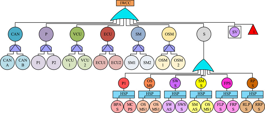
Figure 1. IWCC system FTA.
In Figure 1, the cut sets of the top event IWCC are Controller Area Network (CAN), P, Vehicle Control Unit (VCU), Electronic Control Unit (ECU), Steering Motor (SM), Oil Source Motor (OSM), Sensor (S), and Solenoid Valve (SV). Static subtrees do not have backup components, and their fuzzy inefficiency represents the selection of classical triangular fuzzy numbers, simplified from trapezoidal fuzzy numbers. Static subtree fuzzification utilizes a fuzzy logic gate structure to solve for the fuzzy failure rate values from the bottom event to the top event. If the basic event only includes two functional states: working and failure, and all components in the system are assumed to have no repairable probability, then the failure situation can be solved through the failure relationship of the static subtree. According to the principle of extension and fuzzy logic gates, the membership function for the fuzzy failure efficiency of the top event can be obtained. According to the extension principle in fuzzy logic, the mapping
The confidence interval of the cut set
Among them, the upper boundary
The lower boundary
Based on the above, the fuzzy operator of the OR gate structure function is combined to calculate the fuzzy failure efficiency of the static subtree, as shown in Equation 5.
Due to the possible dynamic faults and failure transitions of components in the IWCC system architecture, this study analyzed systems that experience external disturbances during operation using Markov transition matrices and dynamic fault trees combined with trapezoidal fuzzy numbers. In the FM model, considering the uncertainty of state or transition probability, fuzzy sets or fuzzy mathematics methods are introduced to make the state or probability in the Markov process fuzzy. This method can better handle problems caused by uncertainty and fuzziness, and is suitable for system modeling and analysis scenarios with fuzziness. Therefore, the failure transition process of dynamic FTA is represented by Markov chains, and the fuzzy failure rate of the bottom event is represented by trapezoidal fuzzy numbers (Wellendorf et al., 2023). The trapezoidal fuzzy number can more accurately reflect the fuzziness in system performance, as it allows defining an interval rather than just a point, thus considering the possible states of the system more comprehensively. By using trapezoidal fuzzy numbers, the system can more robustly cope with various situations when facing uncertainty, reducing performance fluctuations caused by inconsistencies or random changes. The trapezoidal fuzzy number is a quadruple
In Equation 6,
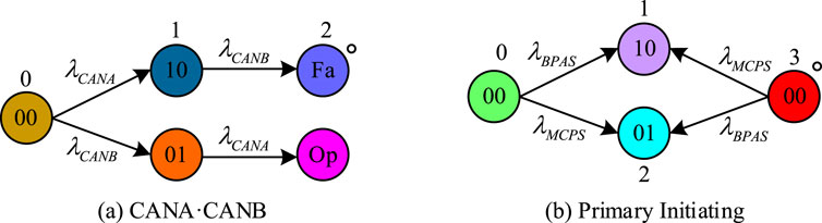
Figure 2. FM model diagram. (A) CANA·CANB. (B) Primary Initiating.
In Figure 2, the top events CANA and CANB, as well as the 00 in the primary triggering event, indicate that the component has not failed, while 10 and 01 are intermediate transition states, indicating that one component has failed with a failure structure of 0-1-2. After the FM differential equation is transformed, the derivative FF of the probability of the system in state
In Equation 7,
The relationship expression of the original equation
Therefore, the matrix expression of the failure efficiency
In Equation 10,
The failure rate
In the hardware design of the IWCC system, the actuator adopts SBW and EHB. SBW uses electronic signals instead of mechanical connections to rotate the wheels of the vehicle. This technology eliminates the mechanical connections in traditional mechanical steering systems, making vehicle steering more flexible and precise. EHB is a braking system based on electronic signal control, combining the advantages of traditional hydraulic brakes and ECU. The EHB system controls the pressure of the brake through electronic signals, enabling faster and more accurate braking operations. To improve the handling, safety, and driving experience of new energy vehicles, a combination design will be conducted. At the same time, to avoid vehicle rollover, the safety requirements of SBW and EHB are designed as ASIL C and ASIL A respectively, and the combination of the two is designed to achieve ASIL D of the system. The independent components CAN bus, vehicle controller, and power supply meet the D-level requirements. Implementing this hierarchical safety design during the operation of new energy vehicles can prevent serious accidents such as rollovers. The functional safety hardware architecture of the IWCC system needs to consider strict security requirements. Therefore, the functional safety design of the IWCC controller is shown in Figure 3.
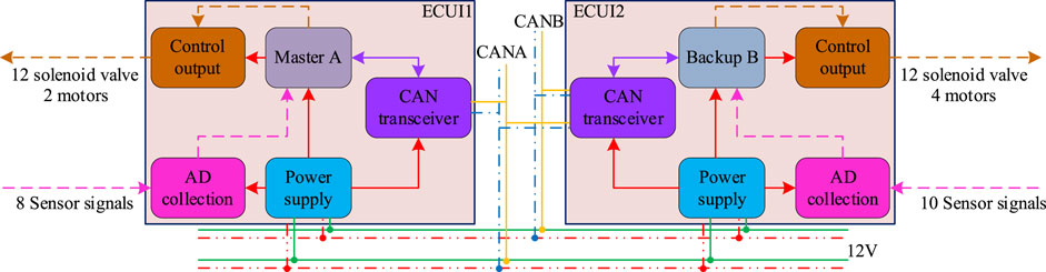
Figure 3. Functional safety design of integrated wire controlled chassis controller.
In Figure 3, the level conversion requirement of EHB relies on the power scheme construction in ECUI to ensure the level matching and conversion required for normal system operation. The main control chip A of ECUI1 is responsible for AD acquisition, controlling the output of motors and solenoid valves, as well as CAN communication between other controllers. The backup chip B of ECUI2 receives the same data and compares and checks the functional operation of A. If backup B discovers an error report fault code, main control A can replace B to ensure the correctness and continuity of system functionality. The pioneering group of Automotive Open System Architecture (AUTOSAR) defined a software architecture for controllers, which separates the hardware and software of devices and puts functional model software and software components together which is independent of each other and developed by different manufacturers, combined into a specific project through certain automated configuration processes. Its function is to achieve interoperability and software reusability between automotive ECUs, and to improve the flexibility, maintainability, and scalability of the system (Bandur et al., 2021). The level conversion requirements in the EHB system are constructed and implemented by the power scheme in ECUI, and the modularity, independence, and interoperability of the system are achieved through the AUTOSAR software architecture standard to improve the reliability and maintainability of the system. The schematic diagram of the redundant algorithm for the electromagnetic valve components in the IWCC system is shown in Figure 4.
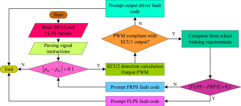
Figure 4. Schematic diagram of redundant algorithm for electromagnetic valve components in IWCC system.
In Figure 4, the exclusive method is selected for fault detection of automotive solenoid valve components. After reading the BPAS and FLPS signals, they are analyzed. When the absolute value of the difference between the ideal braking force and the actual braking force is greater than 0.1MPa, PWM is output through ECU2 detection calculation. Whether PWM meets the output of ECU1 is needed to be determined. If it does, FBV, FCV, and FRIV are used to complete the braking requirements. Then a braking judgment is performed to see if the absolute difference between FLPS and FRPS is greater than 0.1 MPa. If it does, a FLPS fault code will be displayed. Otherwise, an FRPS fault code will be displayed, and then the system will return to re-evaluate the braking force. If PWM does not comply with ECU1 output, a driver fault code will be displayed. The corrected braking torque
In Equation 13,
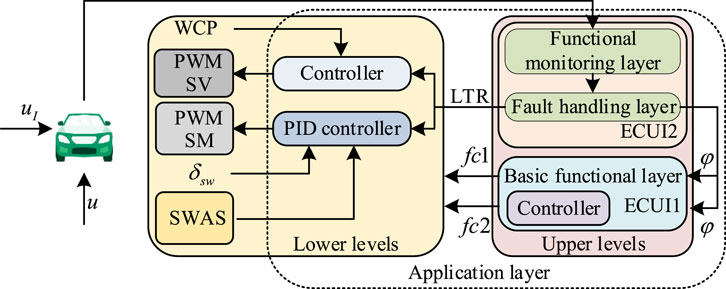
Figure 5. Schematic diagram of anti-rollover control strategy for IWCC system design.
In Figure 5, the speed of the new energy vehicle participating in the experiment is
In Equation 14,
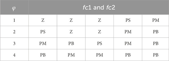
Table 1. IWCC anti-rollover fuzzy control rule table.
Research analyzed the fault factors of EHB and SBW in the IWCC system, and performed performance analysis on their hardware separately to obtain fuzzy failure efficiency and determine the safety level. Simultaneously, error comparison analysis was conducted with different control strategies to evaluate the effectiveness of anti-rollover measures.
The study conducted simulation on the CarSim vehicle model to determine the weak links of the system, studied the importance of components, and analyzed the importance of different influencing factors of EHB and SBW systems, as shown in Figure 6.
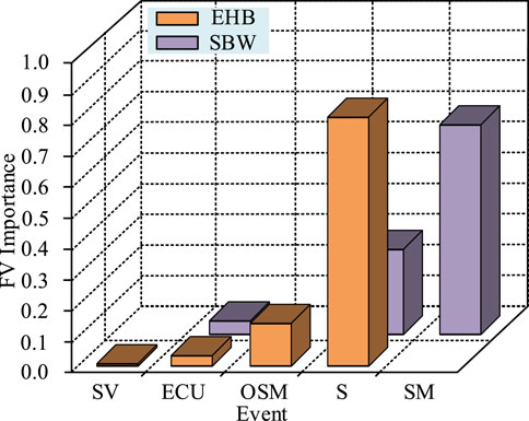
Figure 6. Comparison of importance results between EHB and SBW systems.
In Figure 6, the FV importance of sensor faults in EHB and SBW systems was 81.21% and 68.06%, respectively, both of which were the highest proportions. The FV importance of steering motor faults and ECU faults in the SBW system of the EHB system was 27.42% and 4.51%, respectively. Therefore, in the subsequent maintenance of the car, sensors can be monitored to ensure the reliability and safety of the system. Based on the importance ranking results of EHB and SBW systems, redundant design of functional components was carried out, followed by the completion of FTA model construction, and the failure rates of the two systems were obtained. Meanwhile, considering the uncertainty and fuzziness of car rollover events, to verify the properties of the FM model, the fuzzy failure efficiency membership functions of event CAN and top event IWCC per unit time were studied, as shown in Figure 7.
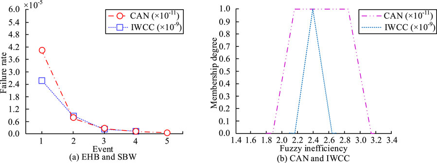
Figure 7. Comparison of membership functions for system redundancy results and time fuzzy inefficiency. (A) EHB and SBW. (B) CAN and IWCC.
In Figure 7A, the initial failure rate of the EHB system was 4.002E-05, Event 2 was a sensor failure with a failure rate of 7.521E-06, and Event 5 had a failure rate of 1.098E-09. The initial ASIL of the system was 2.527E-05, and by Event 2, the redundancy result decreased to 8.07E-06, with the fastest decrease in inefficiency. The failure rates of Events 3 and 4 were 1.14E-06 and 3.456E-10, respectively. At this time, the failure rates of the SBW system with full redundancy design could meet the D-level requirements. In Figure 7B, when the membership degree of the event CAN was 1 at any intersection, the maximum value of the fuzzy inefficiency interval was 2.862 × 10⁻¹¹ per hour. The fuzzy failure rate of the designed system top event was 2.403 × 10⁻⁹ per hour, and the other 8 sub events met the level requirements of ASIL decomposition after modular decomposition of the IWCC system. This indicates that the safety measures of the IWCC architecture meet the ASIL D-level standard. The fuzzy failure efficiency results obtained by using FM to calculate the various cut sets of the top event IWCC are shown in Table 2.
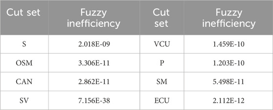
Table 2. The failure rate of cut sets and top events in different systems.
In Table 2, the cut sets in this study could determine the complexity and degree of impact of IWCC system faults. The fuzzy failure rate of sensor failure was higher, at 2.018E-09. This indicated that sensor failures had a significant impact on the overall reliability of the studied system, and therefore it needs to be carefully considered in subsequent diagnosis and monitoring.
The results were verified in CarSim simulation tool for different control strategies, and the analysis of wheel angle errors was studied under the condition of car turning angles. By maintaining the same conditions, the effects and performance of different control strategies in reducing wheel angle errors were compared and analyzed, the obtained wheel angle errors are shown in Figure 8.
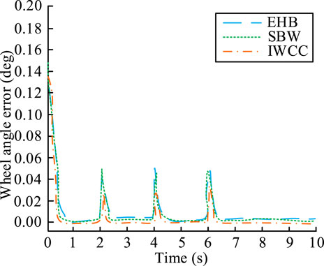
Figure 8. Comparison of wheel angle errors under different control strategies.
In Figure 8, the wheel angle errors of EHB and SBW were similar, and the variation curves were almost identical. There were some similarities in the system responses of the two. The IWCC control strategy had a smaller variation in wheel angle error compared to the two, maintaining within 2e-3deg, indicating better vehicle performance. The smaller range of error variation indicated that the IWCC control strategy had more reliable control performance, which helped to improve vehicle handling and safety. Research was conducted on simulating the driving situation of vehicles under the IWCC control strategy in a simulation model, with a speed input of 5 m/s, to obtain a comparison of the changes in the center of mass sideslip angle, lateral acceleration, yaw rate, and body roll angle over time, as shown in Figure 9.

Figure 9. Real time vehicle information changes over time. (A) Center of mass lateral deviation angle and yaw. (B) Roll angle and lateral acceleration.
In Figure 9A, the vehicle’s yaw rate remained at 0.10 rad/s after 1 s, and the center of mass lateral deviation angle was approximately 0.025 rad after 3 s. This indicated that the vehicle was performing a stable steering action and had good lateral stability. In Figure 9B, the vehicle’s roll angle was approximately 0.14 rad after 2 s, and its lateral acceleration remained at around 0.5 m/s2 after 1.7 s. The acceleration experienced by the vehicle in the lateral direction was constant, and the value of the acceleration was relatively low, resulting in good interior comfort. To evaluate the performance of new energy vehicles under step operating conditions, a study was conducted with a set speed of 120 km/h and a steering wheel angle of 120°. The anti-roll control effects of uncontrolled, EHB, SBW, and IWCC systems were compared, as shown in Figure 10.
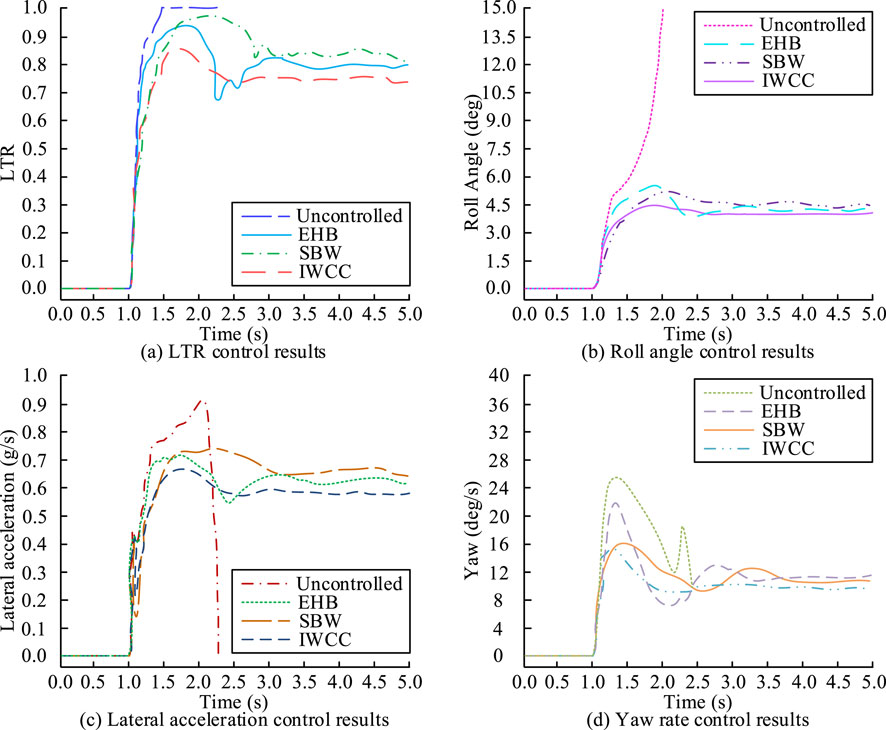
Figure 10. Comparison of anti-rollover control effects of IWCC system. (A) LTR control results. (B) Roll angle control results. (C) Lateral acceleration control results. (D) Yaw rate control results.
In Figure 10A, the LTR values of the four control scenarios remained at 0 before 1.0 s, and the LTR changes were the largest between 1.0 and 1.5 s. The car rolled over without control for 2.3 s, while the maximum LTR value of the IWCC system was 0.75. In Figure 10B, the peak roll angle of the 1.9 s EHB system was 5.8 deg, while that of the IWCC system was 4.5 deg, a 10% decrease in comparison. In Figure 10C, there was a step turn at 1.0 s, and the maximum lateral acceleration fluctuation under the control of the IWCC system was 0.9 g/s. At this point, the IWCC system could support the upper level fuzzy integrated control algorithm, meet functional safety requirements, and avoid vehicle rollover. In Figure 10D, at 1.3 s, the EHB system control had a high yaw rate of approximately 21.8 deg/s. The IWCC system changed the driving state on the basis of the EHB system, with little fluctuation in its yaw rate, which was about 10.5 deg/s. The addition of SBW control could adjust the interior comfort of the car. This study compared and analyzed the applicability of control strategies such as Proportional Integral Derivative (PID) control, proposed control, and Model Predictive Control (MPC) in IWCC systems, and evaluated the performance of IWCC systems under different driving conditions such as wet and slippery roads and sharp turns. The changes in body roll angle of different control strategies in two actual scenarios within the same time period were compared, as shown in Figure 11.
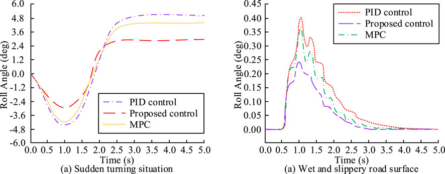
Figure 11. Changes in vehicle body roll angle under two practical scenarios with different control strategies. (A) Sudden turning situation. (B) Wet and slippery road surface.
In Figure 11A, during sharp turns, the body roll angle of the control strategy proposed for new energy vehicles was generally within 3.0 deg. This control strategy could respond more quickly to system state changes and had better handling capabilities for nonlinear characteristics. The maximum change in roll angle was controlled by PID. This was because PID control was suitable for simple systems, but it reacted slowly in nonlinear and complex dynamic situations, and produced significant overshoot and oscillation during rapid changes. In Figure 11B, on a wet and slippery road surface, the control strategy proposed by the new energy vehicle could quickly restore the body roll angle to 0 deg compared to MPC and PID control, that is, restore the body stability. MPC had a large computational load, poor real-time performance, and unstable performance in rapidly changing dynamic scenarios. Within 5 s, the body roll angle change curve was relatively smooth, with a maximum roll angle of less than 0.25°, indicating that the proposed control strategy was more stable.
To ensure vehicle safety and avoid rollover, the FM control strategy was studied and selected. The IWCC system was designed, and its fuzzy failure efficiency was analyzed. The safety integrity level of the vehicle was verified through FTA. The results indicated that the FV importance of sensor faults in EHB and SBW systems was 81.21% and 68.06%, respectively, both of which were the highest proportions. The FV importance of steering motor faults and ECU faults in the SBW system of the EHB system was 27.42% and 4.51%, respectively. The other 8 sub events achieved the level requirements of ASIL decomposition after modular decomposition in the IWCC system. The fuzzy failure rate of the top event in the IWCC system was 2.403 × 10⁻⁹ per hour, indicating that the security measures of the IWCC architecture met the ASIL D-level standard. When the membership degree under any cut set of event CAN was 1, the maximum value of the fuzzy inefficiency interval was 2.862 × 10⁻¹¹ per hour. The initial failure rate of the EHB system was 4.002E-05, Event 2 was a sensor failure with a failure rate of 7.521E-06, and Event 5 had a failure rate of 1.098E-09. The initial ASIL of the SBW system was 2.527E-05, and by Event 2, the redundancy result decreased to 8.07E-06, with the fastest decrease in inefficiency. The failure rates of Events 3 and 4 were 1.14E-06 and 3.456E-10, respectively. At this time, the failure rates of the SBW system with full redundancy design could meet the D-level requirements. The wheel angle error of EHB and SBW was similar, and the change curve was almost the same. The IWCC control strategy had a smaller change in wheel angle error compared to the two, maintaining within 2e-3deg. At 1.9 s, the peak roll angle of the IWCC system was 4.5 deg, a 10% decrease in comparison. There was a step turn at 1.0 s, and the maximum fluctuation in lateral acceleration under the control of the IWCC system was 0.9 g/s. This indicated that the IWCC system has improved vehicle safety performance, enhancing the anti-rollover control force while ensuring small errors. However, due to time constraints, the changes in wheel angles caused by weather factors were not compared, and further research can be conducted here in the future.
The original contributions presented in the study are included in the article/supplementary material, further inquiries can be directed to the corresponding author.
GW: Conceptualization, Data curation, Formal Analysis, Funding acquisition, Investigation, Methodology, Project administration, Software, Supervision, Writing–original draft, Writing–review and editing.
The author(s) declare that financial support was received for the research, authorship, and/or publication of this article. The research is supported by the Henan Province Science and Technology Research and Development Program Project (242102210029).
The author declares that the research was conducted in the absence of any commercial or financial relationships that could be construed as a potential conflict of interest.
All claims expressed in this article are solely those of the authors and do not necessarily represent those of their affiliated organizations, or those of the publisher, the editors and the reviewers. Any product that may be evaluated in this article, or claim that may be made by its manufacturer, is not guaranteed or endorsed by the publisher.
Ataei, M., Khajepour, A., and Jeon, S. (2019). A general rollover index for tripped and un-tripped rollovers on flat and sloped roads. Proc. Ins. Mech. Eng. Part D J. Automob. Eng. 233 (2), 304–316. doi:10.1177/0954407017743345
Ataei, M., Khajepour, A., and Jeon, S. (2020). Model predictive rollover prevention for steer-by-wire vehicles with a new rollover index. Int. J. Cont. 93 (1), 140–155. doi:10.1080/00207179.2018.1535198
Bandur, V., Selim, G., Pantelic, V., and Lawford, M. (2021). Making the case for centralized automotive E/E architectures. IEEE Trans. Veh. Technol. 70 (2), 1230–1245. doi:10.1109/tvt.2021.3054934
Cheng, J., Shan, Y., Cao, J., and Park, J. H. (2020). Nonstationary control for T–S fuzzy Markovian switching systems with variable quantization density. IEEE Trans. Fuzzy Syst. 29 (6), 1375–1385. doi:10.1109/tfuzz.2020.2974440
Cheng, P., He, S., Stojanovic, V., Luan, X., and Liu, F. (2021). Fuzzy fault detection for Markov jump systems with partly accessible hidden information: an event-triggered approach. IEEE Trans. Cybern. 52 (8), 7352–7361. doi:10.1109/tcyb.2021.3050209
Choudhuri, S., Adeniye, S., and Sen, A. (2023). Distribution alignment using complement entropy objective and adaptive consensus-based label refinement for partial domain adaptation. Artif. Intell. Appl. 1 (1), 43–51. doi:10.47852/bonviewaia2202524
Dandiwala, A., Chakraborty, B., Chakravarty, D., and Sindha, J. (2023). Vehicle dynamics and active rollover stability control of an electric narrow three-wheeled vehicle: a review and concern towards improvement. Veh. Syst. Dyn. 61 (2), 399–422. doi:10.1080/00423114.2022.2046810
Han, K. J., Park, K. Y., Choi, Y. G., and Kim, K. D. (2023). Design of high-tension elastic cable barriers preventing rollover and climbing-over of various vehicles with high impact severity. Int. J. Crashworth. 28 (1), 55–81. doi:10.1080/13588265.2022.2074632
Hu, M. J., Park, J. H., Cheng, J., and Xie, L. (2023). Security fuzzy control of nonlinear semi-Markov switching systems with event-based mechanism and hybrid cyber-attacks. IEEE Trans. Syst. Man, Cybern. Syst. 53 (9), 5910–5921. doi:10.1109/tsmc.2023.3277554
Jamadar, N. M., and Jadhav, H. T. (2021). A review on braking control and optimization techniques for electric vehicle. Proc. Ins. Mech. Eng. Part D J. Automob. Eng. 235 (9), 2371–2382. doi:10.1177/0954407021996906
Jin, Z., Yan, Z., and Zhao, W. (2022). Rollover stability and anti-roll control of sport utility vehicle with driver in the loop. Int. J. Veh. Des. 90 (1-4), 19–41. doi:10.1504/ijvd.2022.129162
Liu, J., Ran, G., Huang, Y., Han, C., Yu, Y., and Sun, C. (2021). Adaptive event-triggered finite-time dissipative filtering for interval type-2 fuzzy Markov jump systems with asynchronous modes. IEEE Trans. Cybern. 52 (9), 9709–9721. doi:10.1109/tcyb.2021.3053627
Qian, X., Wang, C., and Zhao, W. (2020). Rollover prevention and path following control of integrated steering and braking systems. Proc. Ins. Mech. Eng. Part D J. Automob. Eng. 234 (6), 1644–1659. doi:10.1177/0954407019896502
Ran, G., Li, C., Sakthivel, R., Han, C., Wang, B., and Liu, J. (2022). Adaptive event-triggered asynchronous control for interval type-2 fuzzy Markov jump systems with cyberattacks. IEEE Trans. Control Netw. Syst. 9 (1), 88–99. doi:10.1109/tcns.2022.3141025
Saeedi, M. A. (2020). A new robust combined control system for improving manoeuvrability, lateral stability and rollover prevention of a vehicle. J. Multi-body Dyn. 234 (1), 198–213. doi:10.1177/1464419319887818
Shi, Y., Huang, Y., and Chen, Y. (2021). Trajectory planning of autonomous trucks for collision avoidance with rollover prevention. IEEE Trans. Inte. Transp. Syst. 23 (7), 8930–8939. doi:10.1109/tits.2021.3088293
Van Tan, V. (2021). Preventing rollover phenomenon with an active anti-roll bar system using electro-hydraulic actuators: a full car model. J. Appl. Eng. Sci. 19 (1), 217–229. doi:10.5937/jaes0-28119
Wang, C., Wang, Z., Zhang, L., Cao, D., and Dorrell, D. G. (2020a). A vehicle rollover evaluation system based on enabling state and parameter estimation. IEEE Trans. Indu. Inf. 17 (6), 4003–4013. doi:10.1109/tii.2020.3012003
Wang, J., Xia, J., Shen, H., Xing, M., and Park, J. H. H. (2020b). $\mathcal {H}_{\infty }$ synchronization for fuzzy Markov jump chaotic systems with piecewise-constant transition probabilities subject to PDT switching rule. IEEE Trans. Fuzzy Syst. 29 (10), 3082–3092. doi:10.1109/tfuzz.2020.3012761
Wellendorf, A., Tichelmann, P., and Uhl, J. (2023). Performance analysis of a dynamic test bench based on a linear direct drive. Archives Adv. Eng. Sci. 1 (1), 55–62. doi:10.47852/bonviewaaes3202902
Xue, M., Yan, H., Zhang, H., Sun, J., and Lam, H. K. (2020). Hidden-Markov-model-based asynchronous H∞ tracking control of fuzzy Markov jump systems. IEEE Trans. Fuzzy Syst. 29 (5), 1081–1092. doi:10.1109/tfuzz.2020.2968878
Yang, E., Xie, C., Ou, J., Zhang, S., and Qin, L. (2023). Active roll control for rollover prevention of semi-trailers with robust invariant set. Int. J. Veh. Des. 93 (3), 226–242. doi:10.1504/ijvd.2023.135496
Zhang, L., Lam, H. K., Sun, Y., and Liang, H. (2019). Fault detection for fuzzy semi-Markov jump systems based on interval type-2 fuzzy approach. IEEE Trans. Fuzzy Syst. 28 (10), 2375–2388. doi:10.1109/tfuzz.2019.2936333
Zhang, L., Zong, G., Zhao, X., Zhao, N., and Sharaf, S. (2023). Reachable set control for discrete-time Takagi–Sugeno fuzzy singular Markov jump system. IEEE Trans. Fuzzy Syst. 31 (9), 3173–3184. doi:10.1109/tfuzz.2023.3245634
Keywords: new energy vehicles, wire controlled chassis system, fuzzy markov, fault tree, roll over control
Citation: Wang G (2025) The risk control of rollover safety for new energy vehicles based on wire controlled chassis system. Front. Mech. Eng. 10:1411552. doi: 10.3389/fmech.2024.1411552
Received: 03 April 2024; Accepted: 16 December 2024;
Published: 07 January 2025.
Edited by:
Alpaslan Atmanli, National Defense University, TürkiyeReviewed by:
Siamak Pedrammehr, Tabriz Islamic Art University, IranCopyright © 2025 Wang. This is an open-access article distributed under the terms of the Creative Commons Attribution License (CC BY). The use, distribution or reproduction in other forums is permitted, provided the original author(s) and the copyright owner(s) are credited and that the original publication in this journal is cited, in accordance with accepted academic practice. No use, distribution or reproduction is permitted which does not comply with these terms.
*Correspondence: Guosheng Wang, d2FuZ2d1b3NoZW5nMDA3QDEyNi5jb20=
Disclaimer: All claims expressed in this article are solely those of the authors and do not necessarily represent those of their affiliated organizations, or those of the publisher, the editors and the reviewers. Any product that may be evaluated in this article or claim that may be made by its manufacturer is not guaranteed or endorsed by the publisher.
Research integrity at Frontiers
Learn more about the work of our research integrity team to safeguard the quality of each article we publish.