 Yongcheng Mu
94% of researchers rate our articles as excellent or good
Learn more about the work of our research integrity team to safeguard the quality of each article we publish.
Find out more
ORIGINAL RESEARCH article
Front. Mech. Eng., 04 July 2024
Sec. Digital Manufacturing
Volume 10 - 2024 | https://doi.org/10.3389/fmech.2024.1397767
Introduction: As an economical and fast process method for surface modification of materials, overlay welding is increasingly widely used in the manufacturing and repair of parts in various industrial sectors.
Methods: This study combines grating projection measurement to design an economical mold arc additive process, and introduces point cloud simplification algorithm for wear and repair design of the mold structure. Then, a new method for manufacturing low-cost, long-life, and economical hot stamping die inserts is designed, using low-cost forged steel and cast steel as substrates and surface welding of high-temperature alloy wear-resistant layers.
Results and Discussion: The experiment shows that the proposed algorithm for simplifying scattered molds has a good evaluation effect, without any gaps, and has a good retention effect on point clouds. The maximum and minimum distances are 0.45 mm and 0.025 mm, respectively. The friction coefficient of cobalt based alloys at 300°C is lower than that at 200°C, and the fluctuation period at 200°C is significantly longer than that at 300°C. HSTS steel has the highest wear resistance, and the performance of cobalt-based alloys is significantly better than that of other alloys. The compressive yield strength of iron-based alloys is the highest, and the hardness of iron-based alloys is the highest, at 53.2 HRC. Therefore, iron-based alloys were selected as a surface wear-resistant layer welding material for economical molds with cooling channels, and cobalt-based alloys were also selected as a surface wear-resistant layer welding material for variable strength economical molds. The research results provide a reference for economic mold manufacturing and repair.
Due to a humid external environment and improper construction, molds are prone to damage during use due to factors such as wear and impact, resulting in the molded product not meeting the quality requirements of Li et al. (2021). Mold overlay welding (MOW) technology can be used to repair molds, restore the original size and shape, extend service life, and reduce production costs (Kim et al., 2022). In addition, due to the unstable accuracy and quality of the mold, the quality of the molded products fluctuates greatly, making it challenging to ensure consistent product quality. However, waste and unnecessary operations in the current mold manufacturing process can result in high costs.
In the mold structure design process, point clouds are models composed of many points in three-dimensional space. Point clouds are commonly used in fields such as modeling, data collection, and computer vision. However, point cloud datasets are often very large and must be streamlined to reduce storage space and computational complexity. Based on the above, a new method for manufacturing low-cost, long-life, and economical hot stamping die inserts using low-cost forged steel and cast steel as substrates and surface welding of high-temperature alloy wear-resistant layers is proposed in the study. The method innovatively combines grating projection measurement to design an economical die arc additive process and introduces a point cloud simplification algorithm for the wear and repair design of the die structure. This study proposes a new method for manufacturing low-cost, long-life, and economical hot stamping die inserts (LC-LL-EHSDI) using low-cost forged steel and cast steel (LC-FSCS) as substrates and surface welding of high-temperature alloy wear-resistant layers (HTAWRL-SW). Moreover, this study innovatively combines grating projection measurement (GPM) to design an economical mold arc additive process (AAP) and introduces a point cloud simplification algorithm (PCSA) for the wear and repair design of the mold structure. The article’s structure is described in Part 1, which outlines the research background, significance, and prospects of mold manufacturing and welding processes. Part 2 elaborates on the algorithm flow based on PCSA and the new LC-LL-EHSDI manufacturing method for this design. Part 3 elaborates on the algorithm designed based on Part 2 and conducts verification and analysis of experimental data. Part 4 draws conclusions on the results and the shortcomings of the directions for further exploration.
The essence of mold overlay welding is to use welding methods to melt alloy materials with certain performance characteristics onto the surface of the mold cavity, giving expired molds new performance. In recent years, welding technology for repairing hot forging molds has gradually been widely applied. Li et al. (2022) used ultra-high power laser metal active gas (MAG) composite welding to weld Q235 steel with a thickness of 20 mm to elucidate the influence of heat source configuration on the welding process and joint formation. This confirmed that the configuration of the heat source laser and arc played a crucial role in traditional hybrid welding processes. Wang et al. (2021) studied the wire and arc additive manufacturing (WAAM) method and path planning algorithm of truss structural parts to achieve collision-free rapid prototyping design of truss structures with complex features. Wire feeding and welding speed were important parameters to control the WAAM process when producing truss parts. The inclination angle of the welding torch had an important influence on the quality of the formed truss. To achieve high efficiency and good welding quality for medium-thick steel plates, Zhu et al. (2021) proposed a new laser-assisted rotating arc composite arc laser welding technology. The transfer of droplets was carried out in the periodic alternative mode of rotating spray and short circuit transfer. The low-temperature impact energy of the weld metal center and fusion line was much greater than the relevant demands. Fedorov et al. (2023) studied the surface erosion of ceramic shells during rapid investment casting (RIC) using brittleness testing and microscopic analysis and investigated the effects of different pattern materials, shell coating compositions, and firing temperatures. Acrylonitrile butadiene styrene (ABS) produced the most surface erosion, while polyvinyl butyral (PVB) had the least.
Many scholars have investigated welding process repair, looking at geometric shapes and the influence of many factors. Zhixin et al. (2023) used a combination of fracture analysis and metallographic observation to conduct a failure analysis on DS GTD111 turbine blades repaired by welding technology. The high-temperature oxidation of the fracture surface and the degradation of grain boundaries in the welding zone seemed to be the main causes of many secondary cracks, and the peeling of the TBC surface coating near the fracture surface also accelerated the formation of cracks. Paquet et al. (2021) proposed a new method to produce large hulls using the foam additive manufacturing (FAM) process. FAM has saved time and cost in large-scale mold manufacturing. To expand the understanding of the properties of gypsum powder (GyP) and achieve complex molds for aluminum castings, Giorleo and Bonaventi (2021) divided their research into simple and complex part production capabilities. The GyP performance and the min-mold thickness to support the casting process were studied for simple parts. For complex parts, the study considers the powder removability as a function of geometric complexity, and then evaluates the spray performance under lattice structure manufacturing conditions. All tested geometric shapes could withstand the casting process, demonstrating advantages in complex design. Ming-Yu et al. (2023) developed a series of analysis programs for IC packaging products using the mold flow analysis software Moldex3D, taking into account the influence of many factors, including process, structure, and materials. Compared with the experimental results, the error of the warping data was between 10% and 50%, and the largest error was found in the short direction. The maximum stress of the lead frame was 505.7 MPa over two thermal cycles, and the possible fault location was in the upper left corner of the tube core.
Scholars have conducted many in-depth studies of the welding repair process, combining modern computer technology and related research on different welding methods. Zheng et al. (2022) studied the complex porcelain manufacturing process that combines the 3D printing technology with traditional techniques. The process flow and parameters were provided through experiments, and the structure was analyzed using a field emission scanning electron microscope. We studied the factors affecting the dispensing process, the microstructure of printed materials after dispensing, and pore distribution, aiming to provide a basis for the promotion and application of this process. In order to obtain a good penetration state of the vertical upward position cold metal transfer root weld, Chen et al. (2023) explored characteristic signals that can characterize the geometric shape of the back weld and established a prediction model for the width Wb (Webers) of the back weld. Research has found that the geometric parameters of the two-dimensional top-side melt pool cannot accurately characterize the geometric shape of the back weld seam. After analyzing the electrical signals, characteristic signals representing heat and force during CMT welding were extracted, and a Wb prediction model was established. This model has good accuracy and lays the foundation for subsequent penetration control. By adjusting the laser welding sequence, He et al. (2023) studied the welding heat distribution state and its influence on welding deformation and optimized the welding parameters of thin plates. The results show that compared with continuous welding with a single weld seam, segmented skip welding with a single weld seam has smaller transverse shrinkage, better longitudinal shrinkage control, and lower out-of-plane deformation. Compared with continuous welding with a single weld seam, the transverse shrinkage of segmented skip welding decreased by 7.14%, the average longitudinal shrinkage decreased by 34%, and the deflection deformation decreased by 12.9%. At higher welding speeds, TIG-MIG hybrid welding produces better weld formation than traditional MIG welding. Wu et al. (2022) improved the adaptive heat source and arc pressure model on curved surfaces based on the distribution of tilted TIG-MIG arcs on the plane. A three-dimensional transient model for heat and mass transfer in the molten pool was established, and the influence of various welding parameters on the high-speed TIG-MIG hybrid welding process was analyzed. The effects of TIG current, electrode spacing, and welding speed on this hybrid welding process were simulated, and the quantitative relationship between process parameters, melt pool behavior, and weld beam formation was studied. We simulated and analyzed the heat flux field, temperature field, and fluid flow on the surface and longitudinal section of the molten pool under different welding conditions. The experiment showed that the simulation results are in good agreement with the experimental results.
In summary, researchers have explored different welding performance and material preparation methods for overlay welding technology, but the research level of manufacturing process design based on AAP and MOW technology is still insufficient. Therefore, this study proposes a mold structure design and manufacturing process method based on overlay welding technology. For the economical repair of worn molds, PCSA is designed in combination with GPM, providing a technical basis for the economical preparation and repair of molds.
Welding overlay technology is the main method for mold repair and manufacturing that can directly promote the manufacturing and development of molds (Lynch et al., 2020). This study innovatively adopts GPM to design PCSA for repairing worn molds, improving the utilization rate of molds, and designing a new economical mold manufacturing method based on overlay welding technology.
Welding repair greatly shortens the procurement and manufacturing cycle of new molds and improves the production speed. At the same time, the method of modification and substitution after welding has reduced the number of spare parts for molds, further saving costs. This study proposes a new method for LC-LL-EHSDI manufacturing. Compared to the traditional hot stamping die (HSD) manufacturing method, this new method can significantly reduce manufacturing costs and improve a mold’s lifespan. Using welding technology for repair can reduce the use of new modules and save 25%–75% of costs. Compared with the original mold, repairing a mold by welding can increase its service life by 30%–300% to varying degrees. First, this study uses a mold AAP for re-manufacturing to improve material recycling efficiency. A scattered mold PCSA was designed to solve the problems of blank and blurred features in point cloud processing.
Due to the phenomenon that the obtained mold point cloud cannot be scanned multiple times at once, some areas of the point cloud are too dense, and there are also “hole” defects in the point cloud. Therefore, further optimization is needed for this process. First, spatial partitioning of the point cloud and establishing a discrete point cloud domain are necessary. The study uses the three-dimensional grid method to establish spatial topological relationships and then divides discrete points into three categories by establishing the k-neighborhood of the points, obtaining the least squares fitting half surface, and introducing the importance of the points. When the importance of a point is less than the set value a, a 10% uniform sampling method is adopted for simplification as it mostly belongs to planar ordinary points. A fully preserved method is adopted for points with importance greater than the set value b, which are important feature class points. The adaptive simplification method is adopted for ordinary feature class points with importance between a and b. The above method has solved the problem of blank fuzzy features in point cloud processing. Obtaining high-quality mold point clouds makes subsequent graphic processing, layered slicing, and path planning convenient, which can greatly improve efficiency.
Because point clouds are a massive collection of points that express the spatial distribution and surface characteristics of the target in the same spatial reference frame, each step in the actual scanning process is completely based on manual experience, which results in defects such as voids and over density in the obtained point clouds (Gim et al., 2023). Before simplifying the point cloud, it is necessary to measure and scan the distribution of the point cloud. The commonly used scanning technique is grating projection measurement, and the corresponding instrument is a three-dimensional grating photography scanner, as shown in Figure 1A.
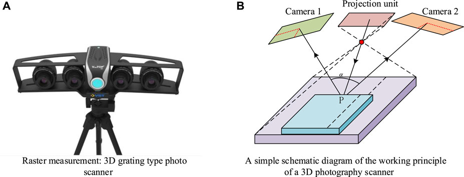
Figure 1. Schematic diagram of the working principle of 3D grating type photo scanner (A) and 3D photo scanner (B).
The projection grating method is a method for measuring the 3D shape and surface deformation of objects. The measurement principle first uses the projection beam
In Eq. 1,
In Eq. 2,
In Eq. 3,
At present, point cloud simplification algorithms inevitably result in noise due to the large number of point clouds. Therefore, a scattered mold point cloud simplification algorithm that can delete a large number of points and retain corresponding features without causing gaps has been designed. The research method is used to optimize the design and design of mold scanning characteristics, subsequent layered slicing, and welding processes in mold structure optimization. The mold point cloud is divided into three categories: planar ordinary points, important feature class points, and ordinary feature class points. Different simplification methods are adopted to effectively solve the problems of “blank” and “fading” in the point cloud processing module in the initial process, which is helpful for the design optimization of mold structures. Due to the unique external characteristics of the mold, the point cloud of the mold can be mainly divided into two parts: the mold cavity feature point cloud on the upper surface and the mold plane point cloud on the four sides. Based on this, the research algorithm adopts a classified simplification of the mold point cloud. First, it is necessary to perform spatial partitioning of the point cloud and establish the domain of discrete point clouds. Considering the processing accuracy of subsequent welding techniques, this study adopts the 3D grid method to establish spatial topological relationships. First, the data are read to construct the minimum bounding box cuboid with the length of the three sides, as shown in Eq. 4.
In Eq. 4, all data point sets are on the x, y, and z axes, where
In Eq. 5,
In Eq. 6,
In Eq. 7,
In Eq. 8,
In Eq. 9,
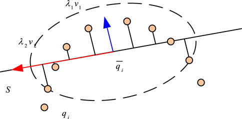
Figure 2. Covariance analysis chart.
The least squares method for fitting a plane is a method of determining the optimal plane model based on the coordinates of data points and their corresponding function values. The basic idea is to determine the optimal plane fitting model by solving the minimum sum of squared errors. This method is used for data analysis and fitting, such as canonical fitting and plane fitting. Its main advantage is that the coefficients of the planar model can be solved through simple mathematical formulas, and it has good stability and reliability. The least squares method can also calculate some related statistics, such as residual sum of squares, correlation coefficient, and standard deviation, which can be used to evaluate the fitting effect and degree of error, thereby helping determine the reliability and accuracy of the fitting model. The plane can be approximated as the local surface of the entity where sampling point
To facilitate subsequent classification and facilitate intuitive representation, this study introduces the importance degree
In Eq. 11, the importance is within [0,1], and the larger the value, the stronger the curvature of the point, which needs to be retained. Conversely, it should be deleted. Figure 3 shows the simplification strategy and specific process for scattered molds.
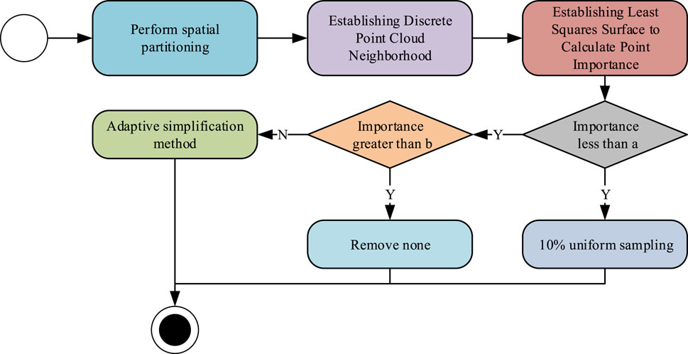
Figure 3. Flowchart of the point cloud simplification algorithm for scattered molds.
Due to the uncertainty of the importance of some point clouds, this study adopts an adaptive simplification method to read the grid in the grid flow label, ensuring that the number of points in the grid is not less than 1 and calculating the weight of the small grid, as shown in Eq. 12.
In Eq. 12, the point cloud is divided into three categories of importance:
In Eq. 13,
The metric for simplification algorithms is geometric error. This study uses the multilevel security assessment (MLS) method to measure the error of the simplified point cloud. The effectiveness of the simplification can be evaluated by calculating the maximum and average distances from points to surfaces, as displayed in Eq. 15.
In Eq. 15,
Applying an alloy coating to the metal surface of a component by welding or spraying to extend the component’s service life is called surface overlay welding (Acherjee, 2020; Bradley, 2022). Based on the mold scanning process described in the previous section, the structure of the economical mold can be optimized. This study considered the low-cost and long-life mold manufacturing method and designed corresponding manufacturing process steps. Mold inserts are used in the manufacturing of molds and can serve various functions such as support, positioning, reinforcement, and protection. The block structure and manufacturing processes are shown in Figure 4.
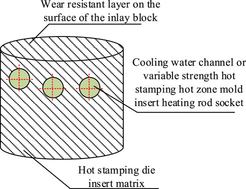
Figure 4. Structure of hot stamping die inserts.
Welding has certain performance requirements, and hot overlay welding is affected by the friction of hot metal during the working process. The material being squeezed exerts a relatively large compressive stress on the mold. Therefore, hot overlay welding should have high strength, hardness, and toughness at high temperatures (Tekanil et al., 2022). This material is mainly high-performance metal, and through overlay welding, it can change the size of the parts and improve the surface performance of the parts economically. Molds are generally divided into molds for processing metals and molds for processing non-metals and powder metallurgy, including plastic molds (such as two-color molds, compression molds, and extrusion molds), rubber molds, and powder metallurgy molds. The manufacturing process of mold inserts is shown in Figure 5.
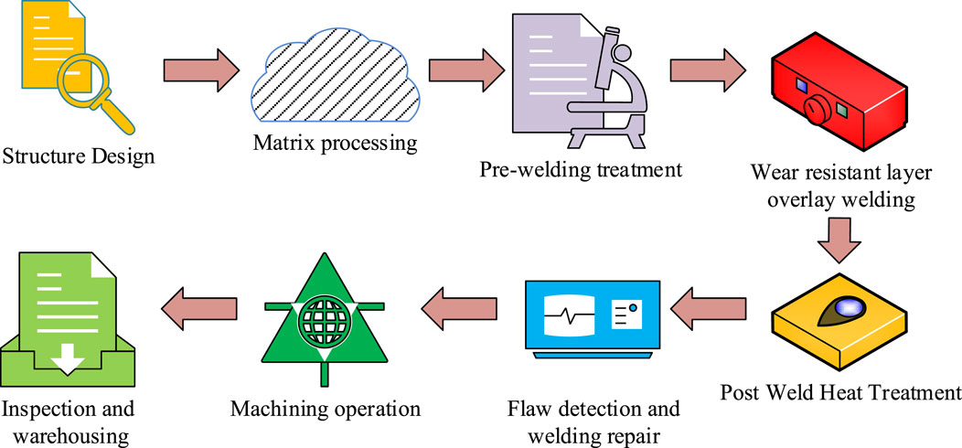
Figure 5. Manufacturing process of hot stamping die inserts.
This study designed a new manufacturing method for LC-LL-EHSDI using LC-FSCS as the matrix and HTAWRL-SW as the binding material. The main process includes the selection of welding materials and the setting of process parameters, pre-welding preparation, welding preheating, welding, and post-welding heat treatment. Machining is the initial step in manufacturing mold inserts. Strict control of machining accuracy ensures that the dimensional tolerance, shape tolerance, and surface roughness of the inserts meet the requirements, ensuring the quality of the mold inserts. Due to the possibility of some defects or damages during the machining process, non-destructive testing is used to detect possible defects inside the mold insert, such as cracks, pores, and inclusions. Through non-destructive testing, potential defects can be detected and dealt with in a timely manner, avoiding fractures or other failure modes during use. Then, molds are repaired by welding to restore the integrity and performance of the insert. During the welding process, it is necessary to control the welding temperature, welding speed, and welding materials to ensure the quality and strength of the welded joints. Post-weld heat treatment is the process of eliminating residual stresses generated during welding, improving the performance of welded joints, increasing toughness, and reducing hardness, thereby increasing the service life of mold inserts. During die forging, the die chamber is in long-term contact with high-temperature forgings, with temperatures reaching 200°C–300°C. The temperature of thinner parts, such as the corners or protrusions of the mold chamber, can even reach 500°C–600°C. In addition, the corners of the mold chamber must also withstand the strong impact force generated during impact and the explosive combustion of the coolant. Therefore, the welding material must have high heat resistance and wear resistance, as well as good impact toughness. Table 1 shows the selection of welding materials and process parameters.
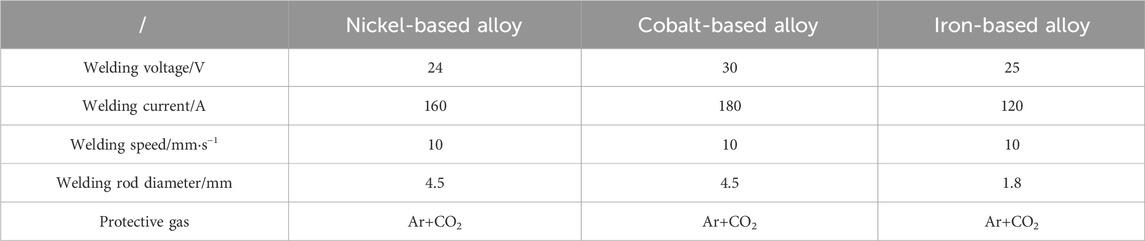
Table 1. Welding process parameters.
When selecting parameters for welding processes and materials, the following standards are adopted: the chemical composition and mechanical properties of the base material, such as carbon content, alloying elements, strength, and toughness, are selected to ensure that the welded joint has similar properties to the base material. Second, the usage environment of welding joints includes factors such as working temperature, pressure, and corrosive media. Factors such as the feasibility of welding methods, welding speed, and heat input are considered. On the premise of meeting the usage requirements, welding materials and processes that are inexpensive and resource rich can reduce production costs. Other considerations include the physical properties of welding materials, such as melting point, thermal conductivity, and coefficient of thermal expansion, and the quality requirements for welded joints, such as the appearance quality, intrinsic quality, and mechanical properties of the weld seam. Finally, it is important to choose welding materials and processes that comply with relevant safety and environmental standards to reduce harm to the environment and operators.
Preparation before welding: Due to the repeated heating and cooling during overlay welding, the contact area between the forging and the mold cavity is large, and the time is long, which can cause cracking and cavity sinking in the overlay. Before welding, the cracks must be removed with a pneumatic shovel, and then the edges of the shovel must be polished with a grinding wheel. Sharp corners should be ground into rounded corners, and the vertical surface should be air-planed into a 10°–15° slope. If cracks occur, all cracks should be air-planed into “U” grooves. Welding preheating: The welding performance of molded steel is poor, and defects such as cracking, slag inclusion, and inter-layer peeling are prone to occur during welding. Therefore, before welding, the mold to be welded should be preheated, and the furnace temperature should be set at 450°C–500°C. The mold should be put into the furnace at 450°C and kept at a constant temperature for 8–10 h. Welding should be carried out when the overall temperature of the mold reaches 450°C or above. Welding method: When the mold temperature is ≥450°C, the mold should be removed from the furnace and placed in a suitable welding position. The mold should be wrapped with asbestos, and only the welding position should be exposed. At the same time, windproof baffles should be set around the mold. Adopting a partitioned and layered welding method, for each layer of welding, a pneumatic pick is used to vertically strike the welding surface to eliminate weld stress and prevent brittle cracking. After cleaning the surface, proceed with the second layer of welding. During welding, attention should be paid to the positions of joints and arc pits, and the joints should be staggered. The overlap distance between welds shall not be less than one-third of the weld width. Post-weld heat treatment: The mold should be tempered after welding to eliminate welding stress and ensure that the hardness of the mold meets the requirements for use. The tempering temperature is 570°C, and the time depends on the mold thickness, with a rate of 1 mm/25.4 h. After two rounds of tempering and one round of tempering, slowly cool to room temperature and discharge from the furnace. The purpose of the first tempering is to eliminate residual stress, and the control range of tempering temperature is generally between 645°C–650°C; The second tempering is to restore the organization to its normal state, and the control range of tempering temperature is generally between 400°C and 650°C, improving the strength, hardness, and related properties of the material, making its performance more stable. Quality inspection of the welding layer: During the welding process, after each layer is welded, a pneumatic pick should be used to knock and remove the welding slag, and it should be cleaned up in a timely manner before re-welding. The current must be controlled during the welding process, and the fluctuation should not exceed 15%. The angle of the welding gun should be adjusted according to the welding position at any time to control the arc length. The temperature changes of the mold should be carefully monitored. If the temperature of the mold is below 350°C, the welding operation should be stopped, and the mold should be heated in the electric furnace. After the mold temperature reaches the required temperature, the welding operation can be continued (Daniyan et al., 2021).
In the proposed new method, low-cost forged steel and cast steel are used as the substrate, and the surface is welded with a high-temperature alloy wear-resistant layer. The low-cost, long-life, and economical hot stamping die insert manufacturing method has the advantage of cost reduction compared to traditional methods. The new method uses low-cost forged steel and cast steel as the substrate, which can significantly reduce manufacturing costs compared to the high-cost materials used in traditional methods. Improving wear resistance: The mold surface is welded to a high-temperature alloy wear-resistant layer, which gives the mold insert higher wear resistance. The mold can maintain a long service life in high-temperature and high-pressure environments. Improving longevity economy: By using point cloud simplification algorithms to determine the structure and optimize material selection and manufacturing processes, the new method can significantly improve the service life of mold inserts, thereby improving production efficiency, reducing maintenance costs, and achieving better economic benefits. In summary, the new method has significant advantages in reducing costs and improving wear resistance and longevity and has important practical application value for the manufacturing of hot stamping die inserts.
An experiment was conducted to verify the performance of the proposed LC-LL-EHSDI manufacturing method with LC-FSCS as the matrix combined with HTAWRL-SW. The advantages and feasibility of the method are verified by analyzing the corresponding design parameters and experimental data, providing a reference for mold reuse and improving economy.
The materials selected for the experiment are nickel-based alloys (NbA), cobalt-based alloys (CbA), and iron-based alloy (IbA) flux-cored welding materials that can be used for manual arc welding. Alloy materials contain 15% chromium and a certain amount of alloy elements such as molybdenum, niobium, and tantalum, which have good high-temperature performance and crack resistance. The chemical composition of the material is listed in Table 2. In addition, the HSTS steel used for mold manufacturing was selected as a comparative reference in the experiment to evaluate the mechanical properties and wear resistance of NbAs, CbAs, and IbA flux-cored welding materials. Research on material and mold testing experiments and comparative research experiments include compressive yield strength testing, room temperature hardness testing, high-temperature wear testing, and basic performance friction coefficient fluctuation experiments. Compressive yield strength testing analyzes the compressive yield strength of materials. The hardness of materials is tested through hardness testing, the wear resistance of materials is analyzed through high-temperature wear tests, and the wear volume of molds is analyzed through basic performance friction coefficient fluctuation experiments. The material selection and process coefficients are comprehensively determined.
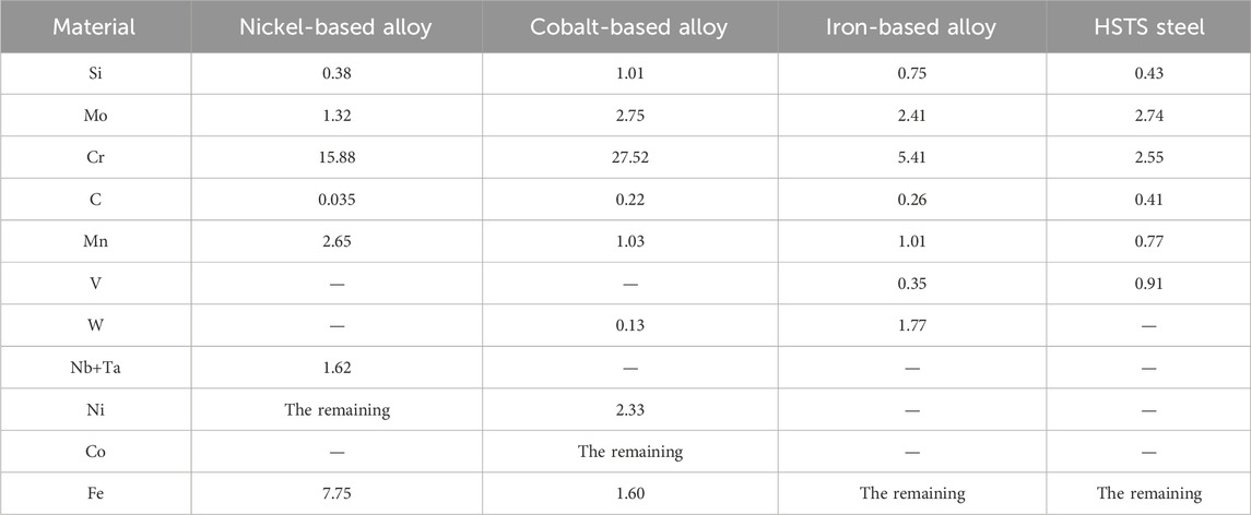
Table 2. Chemical composition of materials (wt. %).
The materials selected during the experiment will be subjected to manual arc welding, and the selected NbA, CbA, and IbA test materials will be strictly welded to the surface of a certain metal block substrate according to relevant process parameters. After multilayer welding, it is necessary to ensure that the minimum size of the total welding layer is 5 mm. Immediately after welding, the samples are loaded into the furnace and tempered at 560°C for 1 h. Then, they are allowed to slowly cool to 180°C with the furnace and moved to air for natural cooling. The heat treatment state of HSTS steel is 1,050°C quenching +550°C tempering for 1 h, followed by wear analysis. After conducting wear experiments on the worn molds, mold AAP was used for re-manufacturing. The scattered mold PCSA was designed for processing, and an additive re-manufacturing model was constructed to analyze the effect. The mold inserts after the experimental welding and mechanical processing are shown in Figure 6.
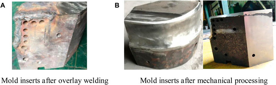
Figure 6. The mold is inserted into (B) after experimental welding (A) and mechanical processing.
In the continuous hot stamping production process, the surface temperature of hot stamping molds with cooling channels is usually within the range of 120°C–300°C, and the surface temperature of variable strength hot stamping hot zone molds is approximately 450°C–550°C. Therefore, 200°C and 300°C are selected as the experimental temperatures for the study. During the forming process, the rounded corners of the hot stamping die are prone to stress concentration and wear. Therefore, in order to approach the service conditions of the hot stamping die more closely, a larger test load of 180 N was selected within the allowable range of the frictional wear test load in this project. In addition, during the hot stamping process, the stamping speed of the press is relatively fast. A higher stamping speed not only improves production efficiency but also helps improve the formability of the hot-stamped sheet metal. Therefore, the reciprocating frequency of the high-speed linear reciprocating friction and wear testing machine for the ball and disc is 4 Hz, which means the sliding friction speed is 64 m/s.
Table 3 shows the evaluation of point cloud simplification effects using different methods. The proposed algorithm for simplifying scattered molds has a good evaluation effect, without gaps, and has a good retention effect on point clouds. The maximum and minimum distances are 0.45 mm and 0.025 mm, respectively. In the uniform method feature preservation of general reverse engineering software, some important point clouds are lost, and there are gaps, with maximum and minimum distances of 0.71 mm and 0.077 mm, respectively. Therefore, studying algorithms has a better effect on mold scanning and repair.
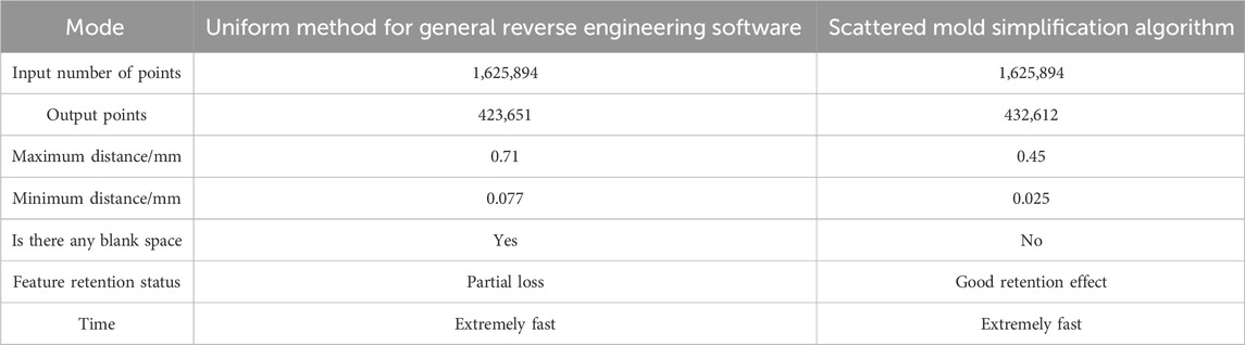
Table 3. Evaluation of point cloud simplification effects using different methods.
Figure 7A shows the results of analyzing the compressive yield strength of four materials at different temperatures. IbAs have the highest compressive yield strength, while NbAs have the lowest compressive yield strength. Figure 7B shows the results of room temperature hardness testing for four materials. IbAs have the highest hardness at 53.2 HRC, while NbAs have the lowest hardness at 14.2 HRC. Therefore, IbAs perform better and have an advantage in compressive yield strength for overlay welding.
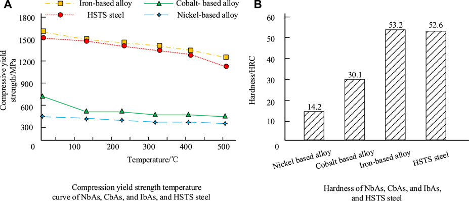
Figure 7. Four different temperature compression yield strength curves and room temperature hardness of materials: compression yield strength temperature curves of NbAs, CbAs, IbAs, and HSTS steels (A), hardness curves of NbAs, CbAs, IbAs, and HSTS steels (B).
In the continuous hot stamping process, the surface temperature of hot stamping molds with cooling channels is usually within the range of 120°C–300°C. Research has selected 200°C and 300°C as experimental temperatures. In order to verify the wear resistance of different surfacing materials on the surface layer of the economic moulds prepared by the analytical study, the study was conducted on some kind of economic moulds with cooling channels surfaced with metal materials, and the wear resistance was analysed at 200°C and 300°C, respectively. Figure 8 shows the depth and width of grinding marks on different welding materials at 20 min and 90 min. Figures 8A, B show marks made at 200°C, and Figures 8C, D show marks made at 300°C. Regardless of the conditions, the wear resistance of NbAs fluctuates the most and shows an unstable state, while the wear resistance of HSTS steel is the most stable.
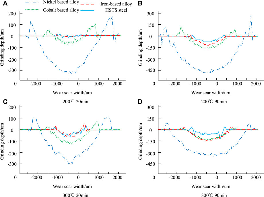
Figure 8. Wear resistance analysis of welding materials under 200°C and 300°C conditions: temperature and time are 200°C for 20 min (A), 200°C for 90 min (B), 300°C for 20 min (C), and 300°C for 90 min (D), respectively.
By observing the depth and width of grinding marks on welding materials at different temperatures, it is possible to identify which materials are more prone to wear at high temperatures. This helps predict the wear trend of the mold in actual work, especially under continuous friction and impact. Based on these data, engineers can choose welding materials that are more suitable for low-cost mold applications. By comparing the grinding trace data of different materials, the most suitable material can be selected for mold design. These data provide a basis for engineers to adjust the operating parameters of the mold in actual work to reduce wear. More reasonable mold maintenance and replacement plans can be developed based on wear prediction and mitigation strategies. Regularly checking the wear of the mold and repairing or replacing it as necessary can ensure that the mold maintains high production efficiency and service life at low cost.
To further analyze the wear performance of welding materials, the experimental statistics of the wear volume of four materials at 200°C and 300°C over time were determined, as shown in Figure 9. Among the four materials, at both 200°C and 300°C, NbAs have the largest wear volume, and the degree of wear increases over time. HSTS steel has the smallest wear volume and the best wear resistance.
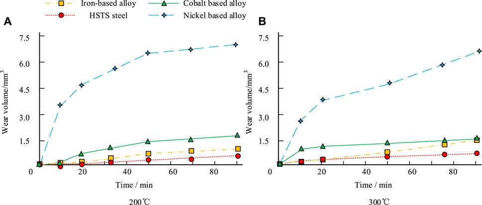
Figure 9. The change of wear volume over time for four materials at 200°C (A) and 300°C (B).
Figure 10 shows field emission scanning electron microscopy (FE-SEM) images of the wear mechanism and appearance of various alloys. In Figure 10A, plastic deformation occurs on the worn surface of the cobalt-based alloy, and a furrow is formed parallel to the sliding direction of the grinding head, with a width of approximately 80 μm–100 μm. The furrow is accompanied by local plastic shear tearing. Figure 10B shows only extremely fine scratches on the worn surface of the iron-based alloy caused by abrasive debris passing over the worn surface. In Figure 10C, the wear mechanism of HSTS steel is mainly abrasive wear, and small scratches and narrow and shallow plow grooves generated by abrasive particles can be observed. At the same time, the small amount of peeling fragments attached to the worn surface can be identified by the corresponding oxygen element distribution map, and these peeling fragments attached to the worn surface are oxide peeling fragments. In Figure 10D, there is an accumulation of oxygen elements in the convex area, while oxygen elements are relatively scarce in the concave area. The raised area is the adhesion area of the oxide layer, while the concave area is the peeling area of the oxide layer.
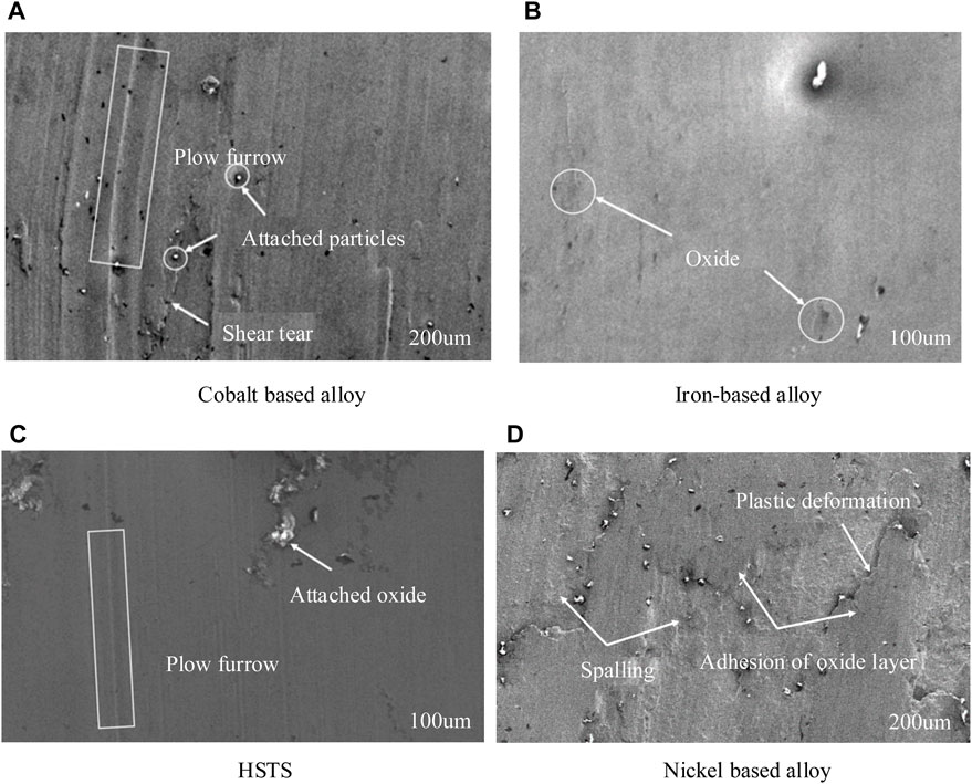
Figure 10. The wear morphology and mechanism of four materials: Cobalt based alloy (A), Iron-based alloy (B), HSTS (C), Nickel based alloy (D).
Figure 11A shows the variation of friction coefficient with time for CbAs at 200°C and 300°C. The friction coefficient of CbAs is lower at 300°C than at 200°C, and the fluctuation period is significantly longer than that at 300°C. Figure 11B shows the basic mechanical properties of CbAs, IbAs, and HSTS steel at room temperature. The performance of CbAs is significantly higher than other alloys, indicating that CbAs have better performance.
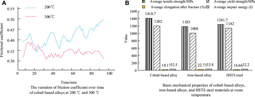
Figure 11. Friction coefficient (A) of CbAs and comparison of basic mechanical properties (B) with IbAs and HSTS steel.
A new method for manufacturing low-cost, long-life, and economical hot stamping die inserts using low-cost forged steel and cast steel as substrates and surface welding of high-temperature alloy wear-resistant layers has been proposed. The experiment evaluates the mechanical properties and wear resistance of nickel-based alloys, cobalt-based alloys, and iron-based alloy flux-cored welding materials by selecting HSTS steel for mold manufacturing as a comparative reference. Therefore, after experimental verification, the proposed method can select the optimal alloy for overlay welding. The overlay welding effect is good and is a good reference value for economical mold manufacturing.
For molds manufactured by overlay welding, the study uses friction coefficient to describe the wear resistance, which is related to the degree of wear of the mold during use. The service life of the mold can be extended by reducing the friction coefficient and reducing wear. Research is conducted on the basic mechanical properties of welding materials, such as tensile strength, yield strength, elongation, etc., which affect the deformation and failure behavior of molds under external forces. Welding materials with good thermal stability and mechanical properties can maintain good mechanical properties in molds working in high-temperature environments, reduce deformation and failure caused by thermal expansion and thermal stress, protect molds from damage, and extend their service life.
The manufacturing cycle of molds in China is generally twice as long as that of industrialized countries, and the service life is only one-fifth. Therefore, improving the lifespan of molds and reducing mold costs is a meaningful task. The use of overlay welding to manufacture molds, repair damaged molds, and repair welding to manufacture molds that exceed the standard has been applied in many types of molds. To improve the economics of molds, this study designed a PCSA for repairing scattered molds and proposed a new LC-LL-EHSDI method using LC-FSCS as the matrix and HTAWRL-SW. Experimental data showed that the friction coefficient of CbAs was lower at 300°C than at 200°C, and the fluctuation period was significantly longer than that at 300°C. The basic mechanical properties of CbAs were significantly higher than that of other alloys, indicating that CbAs had better performance. IbAs had the highest compressive yield strength, while NbAs had the lowest. IbAs had the highest hardness at 53.2 HRC, while NbAs had the lowest at 14.2 HRC. In summary, this study provides a relatively significant reference value for the economical manufacturing of molds. The study combines a point cloud simplification algorithm, surface coating, and modification of mold models in surface engineering technology and introduces overlay welding technology. The results use wear tests in tribology testing, friction coefficient measurement, microstructure analysis in material characterization, and mechanical performance testing to understand the impact of mechanical properties of mold materials on wear resistance. The use of finite element analysis and multiphysics field coupling simulation in experiments can effectively reflect the wear resistance of the mold surface and the effectiveness and role of improving production processes. However, this study only analyzed the mechanical properties and high-temperature wear tests of materials in the welding technology. Future research still needs to optimize the manufacturing process and further explore the wear resistance of the mold surface.
The original contributions presented in the study are included in the article/Supplementary Material; further inquiries can be directed to the corresponding author.
YM: writing–original draft and writing–review and editing.
The author declares that no financial support was received for the research, authorship, and/or publication of this article.
The author declares that the research was conducted in the absence of any commercial or financial relationships that could be construed as a potential conflict of interest.
All claims expressed in this article are solely those of the authors and do not necessarily represent those of their affiliated organizations, or those of the publisher, the editors, and the reviewers. Any product that may be evaluated in this article, or claim that may be made by its manufacturer, is not guaranteed or endorsed by the publisher.
Acherjee, B. (2020). Laser transmission welding of polymers - a review on process fundamentals, material attributes, weldability, and welding techniques. J. Manuf. Process. 60, 227–246. doi:10.1016/j.jmapro.2020.10.017
Ahmadi, M., Bozorgnia Tabary, S. A. A., Rahmatabadi, D., Ebrahimi, M. S., Abrinia, K., and Hashemi, R. (2022). Review of selective laser melting of magnesium alloys: advantages, microstructure and mechanical characterizations, defects, challenges, and applications. J. Mater. Res. Technol. 19, 1537–1562. doi:10.1016/j.jmrt.2022.05.102
Aminzadeh, A., Parvizi, A., Safdarian, R., and Rahmatabadi, D. (2021). Comparison between laser beam and gas tungsten arc tailored welded blanks via deep drawing. Proc. Institution Mech. Eng. Part B J. Eng. Manuf. 235 (4), 673–688. doi:10.1177/0954405420962391
Bradley, R. K. (2022). Education in plastics manufacturing: aluminum mold making and injection molding. Int. J. Mech. Eng. Educ. 50 (3), 726–738. doi:10.1177/03064190211051105
Chen, Z., Wang, Z., Wang, F., Liang, X., Liu, W., Wu, S., et al. (2023). Feasibility study on sensing and prediction of backside weld geometry in cold metal transfer welding of X65 pipeline in the vertical-up position. J. Manuf. Process. 85 (1), 1173–1186. doi:10.1016/j.jmapro.2022.12.031
Daniyan, I., Mpofu, K., Ramatsetse, B., and Phuluwa, H. S. (2021). Numerical modeling and validation of Aluminium Friction Stir Welding (FSW) process during railcar manufacturing. Procedia CIRP 97 (2), 7–14. doi:10.1016/j.procir.2020.05.197
Fedorov, K., Ravindran, C., and Fayazbakhsh, K. (2023). Effects of process parameters on friability and surface quality in the rapid investment casting process. Int. J. Adv. Manuf. Technol. 125 (1/2), 731–742. doi:10.1007/s00170-022-10777-0
Gim, J., Yang, H., and Turng, L.-S. (2023). Transfer learning of machine learning models for multi-objective process optimization of a transferred mold to ensure efficient and robust injection molding of high surface quality parts. J. Manuf. Process. 87, 11–24. doi:10.1016/j.jmapro.2022.12.055
Giorleo, L., and Bonaventi, M. (2021). Casting of complex structures in aluminum using gypsum molds produced via binder jetting. Rapid Prototyp. J. 27 (11), 13–23. doi:10.1108/rpj-03-2020-0048
He, Y., Zeng, Y., Li, Z., Guo, Z., Fang, P., Liu, Z., et al. (2023). The effect of laser segmented skip welding on welding distortion and residual stress in butt weld of 6061 aluminum alloy thin plate. Int. J. Adv. Manuf. Technol. 124 (10), 3293–3309. doi:10.1007/s00170-022-10663-9
Kim, H., Kim, J. I., Ryu, S. S., and Jeong, H. (2022). Cast WC-Co alloy-based tool manufacturing using a polymeric mold prepared via digital light processing 3D printing. Mater. Lett. 306 (1), 130979. doi:10.1016/j.matlet.2021.130979
Li, B., Chen, R. S., and Liu, C. Y. (2021). Using intelligent technology and real-time feedback algorithm to improve manufacturing process in IoT semiconductor industry. J. Supercomput. 77 (5), 4639–4658. doi:10.1007/s11227-020-03457-x
Li, Y., Geng, S., Zhu, Z., Mi, G., and Jiang, P. (2022). Effects of heat source configuration on the welding process and joint formation in ultra-high power laser-MAG hybrid welding. J. Manuf. Process. 77, 40–53. doi:10.1016/j.jmapro.2022.02.045
Lynch, P., Hasbrouck, C., Wilck, J., Kay, M., and Manogharan, G. (2020). Challenges and opportunities to integrate the oldest and newest manufacturing processes: metal casting and additive manufacturing. Rapid Prototyp. J. 26 (6), 1145–1154. doi:10.1108/rpj-10-2019-0277
Ming-Yu, L., Yong-Jie, Z., Sheng-Jye, H., Ming-Han, W., Hui-Ping, L., and Chin-Lung, F. (2023). Warpage and residual stress analyses of post-mold cure process of IC packages. Int. J. Adv. Manuf. Technol. 124 (3/4), 1017–1039. doi:10.1007/s00170-022-10436-4
Paquet, E., Bernard, A., Buret, B., Gamier, S., and Le, L. S. (2021). Foam additive manufacturing technology: main characteristics and experiments for hull mold manufacturing. Rapid Prototyp. J. 27 (8), 1489–1500. doi:10.1108/rpj-06-2020-0137
Preethi, P., and Mamatha, H. R. (2023). Region-based convolutional neural network for segmenting text in epigraphical images. Artif. Intell. Appl. 1 (2), 119–127. doi:10.47852/bonviewaia2202293
Saxena, P., Bissacco, G., Meinert, K. L., and Bedka, F. J. (2020). Mold design and fabrication for production of thermoformed paper-based packaging products. J. Manuf. Process. 58, 311–321. doi:10.1016/j.jmapro.2020.07.029
Songhong, Z., and Yingruo, X. (2021). Analysis on wear failure of hot forging die for engine connecting rod based on response surface method. Forg. Stamp. Technol. 46 (7), 178–184. doi:10.13330/j.issn.1000-3940.2021.07.030
Suzuki, A., Fujii, Y., Kimura, T., Kawano, M., and Inazumi, T. (2021). Development of high-accuracy simulation test technology for hot stamping. Mater. Sci. Forum 1016 (2), 1430–1435. doi:10.4028/www.scientific.net/msf.1016.1430
Tekanil, T., Engineer, S., and Rodriguez, M. (2022). Additive manufacturing enables rapid, low-cost stretch blow mold development at PepsiCo. Plast. Eng. 78 (10), 26–27. doi:10.15230/j.issn.0091-9578.2022.07.010
Wang, T., Zhou, X., and Zhang, H. (2021). Control of forming process of truss structure based on cold metal transition technology. Rapid Prototyp. J. 28 (2), 204–215. doi:10.1108/rpj-12-2020-0314
Wu, X., Zhao, X., Chen, J., Zhang, Z., and Wu, C. (2022). Simulation of the influence of welding parameters on weld pool behavior during a TIG-MIG hybrid welding process. J. Manuf. Process. 79, 460–475. doi:10.1016/j.jmapro.2022.05.007
Zheng, H., Ao, H., and Wang, L. (2022). Research on manufacturing technology of complex modeling chinaware integrated with 3D printing technology. Int. J. Multiphysics 16 (4), 395–406. doi:10.13965/j.issn.1750-9580.2022.08.011
Zhixin, Z., Wu, Z., Xiangde, B., and Xiaodong, Z. (2023). Failure analysis of a first stage turbine blade made of directionally solidified GTD111 superalloy and repaired by welding process. Eng. Fail. Anal. 153, 107570. doi:10.1016/j.engfailanal.2023.107570
Keywords: mold, overlay welding technology, economy, wear and tear, point cloud simplification algorithm
Citation: Mu Y (2024) Using surfacing welding technology to manufacture economical molds. Front. Mech. Eng 10:1397767. doi: 10.3389/fmech.2024.1397767
Received: 08 March 2024; Accepted: 30 May 2024;
Published: 04 July 2024.
Edited by:
Kanak Kalita, Vel Tech Dr. RR & Dr. SR Technical University, IndiaCopyright © 2024 Mu. This is an open-access article distributed under the terms of the Creative Commons Attribution License (CC BY). The use, distribution or reproduction in other forums is permitted, provided the original author(s) and the copyright owner(s) are credited and that the original publication in this journal is cited, in accordance with accepted academic practice. No use, distribution or reproduction is permitted which does not comply with these terms.
*Correspondence: Yongcheng Mu, bXljMjAyMzAwN0AxNjMuY29t
Disclaimer: All claims expressed in this article are solely those of the authors and do not necessarily represent those of their affiliated organizations, or those of the publisher, the editors and the reviewers. Any product that may be evaluated in this article or claim that may be made by its manufacturer is not guaranteed or endorsed by the publisher.
Research integrity at Frontiers
Learn more about the work of our research integrity team to safeguard the quality of each article we publish.